1
ENERCON+ JR.
Battery Powered Smart Irrigation Controller4, 8 and 12 Stations
G
TEC REEN
HNO
LOG
Y!
USER’S MANUAL
Patents # 7,058,478, 7,266,428, 7,844,368, and 8,401,705. Other patents pending.
Please fully read all instructions prior to installation and use.
All rights reserved 2013 Rev. 1
TABLE OF CONTENTS
Introduction
Installation Procedure
Existing Installations
New Installations
Electrical Wiring
Existing, and Pre-Existing Field Wiring Schemes
Controller
Rain Switch
Solenoids
Operating Characteristics
Master/Pump Connections:
Output Board Test (OBT) Terminal:
Enercon Panel Controls and Programming
Run/status
Time of Day & Date
Station Assignments
Watering Days
Setting Water Days
Setting Days Interval
Watering Duration
Start Times
Semi-Automatic
Manual
Rain & Station Delay Times
Rain Delay
Station Delay
Stations Test
Budgeting
Manual Budgeting
Monthly Budgeting
Temperature Budgeting
Help/Info
Rain Switch Enable:
Clear Memory:
Output Board STNS:
Output Board Test (OBT):
Minimum Auto Start Temperature
Controller On/Off
Troubleshooting
Battery Replacement
Valve Compatibility
Care & Maintenance
Specifications
Warranty
ALEX TRONIX
Page
1
1
1
2
3
3
3
5
5
6
6
6
7
7
7
8
8
8
9
9
9
9
10
10
10
10
10
10
10
11
11
11
12
12
12
12
13
13
13
15
16
16
17
Back
INTRODUCTION:
Thank you for purchasing the Alex-Tronix Enercon+Jr. Controller. The Enercon is a commercial battery powered smart
irrigation controller, housed in a stainless steel short pedestal, and can operate up to 12 stations with long battery life. Since
a solar panel is not required, maintenance and vandalism are minimized, plus the controller can be installed in shade,
indoors, or under cover. The Enercon+Jr., manufactured in the U.S. by Alex-Tronix, uses proprietary technology recognized
by the U.S. Department of Energy. The Enercon+Jr. technology has been certified for water efficiency under the Smart
Water Application Technology “S.W.A.T.” program and may qualify for cash rebates by many water districts. Please check
with your local water district to apply for any rebates available.
INSTALLATION PROCEDURES
MOUNTING PROCEDURE FOR EXISTING INSTALLATIONS (REFER TO FIG. 1):
The following cautions should be observed:
Do Electrically "ground" controller using a grounding rod.
Do not install the Enercon in a location that will continuously be exposed to sprinkler spray.
Do not install the Enercon near underground high voltage or other utility wiring. Check with local agencies
for cable and wire locations.
Do not allow dirt, water, etc. to enter the controller. Keep cover locked.
Do not spray any cleaners/lubricants into electronics or rotary controls.
Do not attempt to disassemble the face pack- there are no user serviceable parts inside.
Please read the steps below to note which tools and materials are required before beginning installation.
For existing installations that have a concrete pad ready to use, remove old controller and any existing mounting bolts etc.
After preparing the area for installation, check if large concrete cracks or divots remain after removing. If so, use a fast
drying concrete patch such as "pour stone" to tidy things up; let cure.
Locate the chassis lock key, and unlock the Enercon+Jr.’s cover. Remove and gently place aside face up on a clean surface.
Using a phillips screwdriver, remove the four face-pack screws, and slightly lift away from the chassis by grasping the
pulling knob (Do not use function knob). Once the face-pack clears the chassis, turn it to the side, and disconnect the harness
connector by gently pulling on the connector only from side to side. Leave harness in chassis. Place screws and face-pack
aside on the door.
Protrude all wires through the sweep ell in the existing pad and place the chassis on the concrete pad centered around field
wires. Using the empty chassis as a stencil, mark at least four bolt holes on the pad - one on each side of the chassis, or
two each on two sides opposite each other.
ENERCON PLUS JR
1
Step 1) Using a star drill punch, and a 3/8” sized masonry drill bit, drill the four marked holes into the pad approximately 2"
deep - Use caution for not drilling crooked holes. Remove cement dust out of the holes thoroughly.
Step 2) Now take the stainless steel wedge anchors (provided) and tap into each hole leaving ample threading length
- approx. 3/4”-1”
FIGURE 1
Step 3) Fit empty controller chassis over the field wires and route all field wires through the bottom of the pedestal and
align controller over the anchors. remove and apply a liberal bead of waterproof sealant all around the bottom mounting
surface area. Re-seat chassis and place a washer over each anchor stud, then fasten to concrete slab using the four nuts with
a racheting socket or open box wrench. For ease, refer to “ELECTRICAL WIRING” prior to re-installing face pack.
MOUNTING PROCEDURE FOR NEW INSTALLATIONS (REFER TO FIGURE 2):
Step 1) After selecting a location for the controller, excavate an area in the soil to accommodate a concrete form having the
dimensions of 2’ x 2’ x 4”. Depending on the number of wires, place up to a 1-1/2” diameter, long sweep ell pipe centered in
the hole with about a two foot extension laying in the trench. Ensure pipe(s) are vertical with a 2 inch clearance above concrete
level. If you will be installing a rain sensor (optional accessory available from other manufacturers) now is the time to make
additional room for a separate underground conduit if necessary.
Step 2) Though the Enercon+Jr. is electrically isolated from power utility providers, it is highly recommended that a
grounding rod be installed to help reduce static electricity charge build up and lightning strike damage. If your area is prone
to this, then a grounding rod should be installed under or near the pad and at least a 10 AWG wire brought up through the
pedestal a few feet; it must be connected to the marked green ground wire fastened within the chassis. Most building electrical
codes require electrical chassis boxes be grounded.
Step 3) Finally, back fill the hole with soil to a depth of about 5 inches leaving the pipe extension open in the trench.
Step 4) Using 2” X 6” studs, build a wood form to the dimensions of 2' X 2'. Rough in the wood form flush to the ground,
and check with level. The slab should be slightly above sod/ground level so water does not collect on pad.
2
ALEX TRONIX
FIGURE 2
ELECTRICAL WIRING:
NOTE: Please observe all building codes mandated by your locality.
Existing, and Pre-Existing Field Wiring Schemes.
Before installing the Enercon+Jr. controller, you will need to evaluate the wiring plan. If the system was previously a DC
latching system, connect the field common wire(s) to any of the Enercon's common "C" terminals. The majority of latching
solenoids manufactured denote (+ or Red) wire connected to station terminals, and black (- or NEG) wire connected to the
common terminal(s). If you are retrofitting an existing A/C system to the Enercon+ system, the same field wiring may be
used, providing wiring polarity is correct.
It is imperative that all the "common" wires are truly common. This would become a problem if cross wiring were done
somewhere out in the field, which would still allow an AC system to work, but may now have to be corrected for a DC
system. Typically, a white wire is used as a common in AC systems.
A good way to verify polarities once the Enercon+Jr. is installed, is to run the STATIONS TEST (see page 10) function and
observe performance. If a few valves operate erratically, or turn on when they should turn off, check connections and polarity.
For new wiring, always use a separate colored wire for the common (typically black). It is also good practice to color code
station wires or at the least, mark them. This will allow you to trace wires for easier troubleshooting.
Controller Wiring: (Refer to Figures 3)
If valve field wires were not previously marked, they should be at this point. Wire marking kits are available at electrical
supply distributors. Existing field wires should be inspected and re-stripped. Good clean connections to the terminal
strip are crucial. For new installations, use 14 AWG UF (direct burial) SOLID CORE WIRE. NOTE: WIRE RUN
DISTANCE IS SHORTENED WHEN USING SMALLER GAUGES.
Begin wiring station terminals up to 12. There are two common “C” terminals available. Strip all wires approximately 3/8".
Good, clean wire routing is important for ease of troubleshooting. If a ground rod was installed, connect ground rod wire
to the green ground wire ("pigtail") pre-fasted to the terminal harness.
NOTE: The commons marked “C” on output terminal strip are electrically “tied” together. Using all “C” terminals is not
necessary. An extra “C” terminal is provided for convenience and ease of wiring.
ENERCON PLUS JR
3
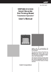
FIGURE 3 Terminal connections shown with temperature
sensor connected
Rain Switch:
If you are planning to install a rain switch, install according to the manufacturers instructions --note, however; the wiring
will be different at the controller. FOR THE ENERCON+Jr. CONTROLLER, DO NOT BREAK OR JUMPER ANY
COMMON WIRES FOR RAIN SWITCH INSTALLATION. The Enercon+Jr. has two dedicated input terminals marked
"RS" on the terminal strip. You must use the N.C. (normally closed) connections from the rain switch. The rain switch
must also be activated through the HELP/INFO function (See HELP/INFO function sub menu -- Rain Switch Enable).
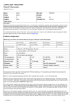
Temperature Sensor Location (refer to fig. 4):
The Enercon+ Jr. is supplied with a temperature sensor designed to be partially
placed into the field wire conduit (sweep ell) entering the chassis. The probe
placed within an inch of ground level yields a relatively accurate ambient
temperature reading without having to install an external pole at another
location, reducing installation labor.
With the temperature higher within the chassis and the ground being at a lower
temperature during the warm season, the balance between the two temperatures can
yield a relatively accurate measurement provided the sensor is optimally
placed within the conduit. The sensor should be tucked within the field
wires in the conduit at ground level. Once the sensor is placed,
connect both wires to the special terminals marked “TS”. The
sensor is used when temperature budgeting (smart
mode) is activated on the controller, and optimum water
saving benefits are achieved.
4
ALEX TRONIX
FIGURE 4
Solenoids:
The Enercon+Jr. only operates 12V DC LATCHING type solenoids. DO NOT CONNECT A/C OR NONLATCHING
DC SOLENOIDS TO THE CONTROLLER. It is highly recommended that the latching solenoid made or recommended
by the valve manufacturer remain with their valve in order to avoid any solenoid/valve compatibility issues. If no factory
made latching solenoid is available for use with the valve specified on the job, then using the Alex-Tronix LS solenoid
is the second option. If using the Alex-Tronix LS, fasten to valve using procedures stipulated by the "Valve
Compatibility Chart" available from Alex-Tronix.
All latching solenoids have a polarity. Typically, black wires are all connected to the common "C" terminal. The remaining red
wires are connected to stations "1 through 12." (Fig 3) If there is doubt about the polarity, a solenoid can be directly connected
to a station on the Enercon’s terminal strip, then tested in MANUAL.
Correct operation is --on "latch"-- the plunger will pull in (water flows through valve); on "release"--plunger will pop out.
(valve shuts off). You will not always be able observe plunger action depending on who manufactures the solenoid; in this
case, it is suggested the manufacturer of the solenoid be contacted for correct polarity and color coding.
When connecting field wires to solenoid wires, make sure the connection is GOOD, CLEAN and TIGHT. Only use gel
filled wire nuts. Mark the field wires at the solenoid to denote polarity. If junction boxes are used in the field, make sure
that the wires are not "crossed" in the box. Correct polarity must be observed, otherwise the solenoid will not operate properly
and the valve will actuate in reverse -It may open, when it should be closed.
Note: If you have an application requiring a normally closed valve, such as a master valve to remain closed when there is
no irrigation, a latching solenoid may be wired in reverse. The valve should be marked so as to not confuse anyone for
future servicing.
Operating Characteristics:
The Enercon+ series controllers are energy efficient battery powered controllers; if several valves are programmed to come
on at the same time, they will actually activate sequentially, several seconds apart from one another. Activation times can
be from 3-8 seconds depending on the condition of the battery. Whenever a station or program is activated by MANUAL,
SEMI-AUTO, AUTOMATIC, or TEST CYCLE, there is always at least a 3 second delay before any solenoid is activated.
The solenoid activation order is as follows: station solenoid output comes on first, then master valve. When valves are to
be turned off, the reverse order occurs with the master, and station solenoid shutting off, each 3-8 seconds apart. If more
than one program is scheduled to start at the same time, the first station assigned to program A will come on first, then the
first station in Program B, then C, then D.
Master/Pump Connections:
When controlling a pump (or other auxiliary device), an optional pump interface kit (P.I.K.-S) available from Alex-Tronix,
must be used. It is connected between a common "C" and master "M" output terminals. The relay can then "make" or "break"
a circuit to control a pump or other device. For this option, contact factory for part availability and connection details.
Output Board Test (OBT) Terminal:
The terminal marked OBT is used to self-test the outputs of the Enercon+Jr. using the OUTPUT BOARD TEST (OBT)
function located under the HELP/INFO menu. Use a short piece of irrigation wire as a probe to test each output by viewing
the L.E.D. status on the back of the face-pack while troubleshooting. (See HELP/INFO -- OUTPUT BOARD TEST).
ENERCON PLUS JR
5
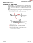
FIGURE 4a - Back view of control panel
Latch and release test
lights for output board
test "OBT"
Solenoid Power
Battery Pack
FIGURE 4b
Panel shown in
position for field
testing
6
ALEX TRONIX
ENERCON+ JR. PANEL CONTROLS AND PROGRAMMING:
Programming capabilities:
•
•
•
•
•
•
•
•
•
•
•
•
Program up to 12 stations-based on the how many stations were specified when ordered.
4 programs with four start times per program.
Watering Days or Days Interval.
Water Durations up to 23 hours and 59 minutes per stations.
Up to four independent Automatic or Semi-Auto starts can be initiated and overlapped.
Manual Starting of any station.
Rain Delay & Station delay.
Automatic Valve Testing Feature.
Smart Temperature, Monthly, and Manual budgeting.
Minimum Temperature (Freeze) Shutdown.
Help and Configuration Menu.
In-field Output Board Station Controller Test (OBT).
The Enercon+Jr. uses a rotary knob and keypad for easy programming. The keypad allows fast data entry, while the function
selector knob gives the feel of user friendly mechanical controllers. The function knob is where all the program information is
viewed and entered. The keypad is used to input program data. Any entry that can be selected or adjusted on the display
has an asterisk symbol "*" next to it. Using the SEL key advances the cursor within the selected function. Please note that
during programming, if you turn the rotary knob off of that position before pressing enter, the entered data will be lost.
Let’s proceed with each function:
To view the display, hold any button down until display appears.
Run/Status: (See display A)
This function displays the controller’s status. In idle, the controller is waiting for the next start time and the current temperature
in degrees Fahrenheit is displayed at the top left. The time of day and current date are on the top line. On the second line,
the day's water budget percentage is also shown when the unit is in temperature budgeting mode.
Display A - No Active Stations, Temperature Budgeting Selected (recommended)
With display shown above, the controller is idle, and awaiting the next start time. Change the time and date on this display
as follows:
TIME OF DAY AND DATE: To enter, change, or correct time of day, press SEL on keypad. You will see a blinking cursor
on the display where the time is located. Using the keypad, enter in the correct time of day and press the key marked
AM/PM. Times that are less than 10 hours must have zero entered in before the next number....For example: 09:23AM.
Press SEL again. The cursor will now move to where the date is located. Enter the date in the following format:
MM/DD/YY. After pressing ENT, the actual day displayed (Su, Mo, etc.) will set itself, because the Enercon has a built
in calendar. The Enercon's calendar accounts for leap year but not daylight savings time. You must reprogram the correct
time if your locale follows DST.
ENERCON PLUS JR
7
When program is running, the display will appear as shown below:
Display B - Active Station(s) With Temperature Budgeting
Duration Time Countdown
(Hours and Minutes Shown)
Program and Station Running
The RUN/STATUS display also provides additional information. When operating automatically, the screen above still indicates
the current temperature, current time, and date and today’s budget on the first two lines, but now shows which program is
active, the station number, and the time remaining in minutes and seconds, or hours, minutes and seconds. In this case, there
is 2 minutes and 41 seconds left of irrigation time on station 1. This is the budgeted remaining watering time. This screen may
also provide additional information depending how it is operating. The display may show up to 4 programs/stations running
at the same time. The display may show up to 4 programs/stations running at the same time. Other information that could be
displayed may be: UNIT IN MANUAL, UNIT IN TEST, CHANGE BATTERIES, RAIN DROP ICON, CONTROLLER
OFF, RAIN DELAY, STATION DELAY, CHECK TEMP SENSOR, TEMPERATURE BUDGET, MANUAL BUDGET,
MONTHLY BUDGET, THIS PANEL NEEDS REPAIR and a % sign indicating duration times are budgeted.
When all programs have finished, the display will show the time, date, and day. It is not necessary for the function knob
to be left on the RUN/STATUS position for automatic operation.
NOTE: When TEMPERATURE BUDGETING is activated, the RUN/STATUS function will display the current temperature after
1 hour on the top left corner of the display, along with the budget method and daily calculated percentage on the second line.
Station Assignments:
For a station to operate a valve in Automatic, Semi-automatic, or Test mode, stations must be assigned to at least one program.
To assign stations, press the SEL key. The cursor is now located on program A. If you continue to press and release SEL,
the cursor will scroll through programs B, C, D, and back to A again. After selecting the program letter, press ENT to go
into the station assignments display for the related program.You are now in the station assignment area for the selected
program. In the lower right hand corner, you will notice a cursor. This is where the station numbers are initially entered. For
example, to assign station number 3, press 03.
To assign stations, key in two numerical digits in succession (up to 12). If you key in stations any higher than the controller
is capable of, you will see ## (pound sign) in the lower right corner of the display. If the station entered is valid, the station
will illuminate on the display at its designated location. You may continue to add additional stations as needed. When finished
entering stations, press ENT to go back to the SELECT PROGRAM display. From this point you can either select another
program to assign stations to, or go to another function. If ENT is not pressed after any function screen programming is
completed, the display will hold the previous screen settings.
NOTE: If you cannot program stations any higher than expected, or more than 12 stations is available, check the OUTPUT
BOARD STNS. configuration setting under the HELP/INFO menu which dictates how many stations are available for use.
Watering Days:
When rotary knob is set to WATERING DAYS, you will have two choices; actual watering days or days interval on any
program. If WATERING DAYS or DAYS INTERVAL are not programmed, the controller will not operate in automatic mode.
SETTING WATER DAYS: To set WATER DAYS, press the SEL key. You will notice the cursor flashing on program A,
indicating the selected program. Press SEL repeatedly to advance to the other programs. Once you have selected the program,
press the keys marked with the day names on them; Sun, Mon, Tues, etc. Pressing each one of these keys illuminates the
8
ALEX TRONIX
watering days on the display. Pressing the same key removes that day. Once all the watering day selections have been
made, press ENT on the keypad to enter in all the days on all programs.
SETTING DAYS INTERVAL: Days interval, also located under the WATERING DAYS function sets the number of days
to skip watering. To set DAYS INTERVAL, press the SEL key. You will notice the cursor flashing on program A,
displaying which program you are in. Press SEL repeatedly to advance to any the other program. Once you have selected the
program, press the key marked: DAYS ITVL. When the days interval option is displayed, you can change the number of
skipped days-- entered on the keypad from 1 to 99 days. When finished, press ENT to enter all four programs on the display.
Watering begins with the same day the interval is programmed as long as the start time(s) have not yet occurred. If you
make any change to any of the four programs (A-D), the programs assigned to the interval of days will reset and a new
starting day begins when you press enter.
Watering Durations:
To set watering duration for all stations, select either bank 1-6 or 7-12 by pressing SEL, then ENT. Once you are in the
desired bank, Press SEL, then SEL again or LEFT/RIGHT (
) arrows to navigate between stations. Once you select
the desired station(s), key in the water time anywhere from 1 minute to 23 hours-- 59 minutes. After setting all the station
watering durations, press ENT to enter in the complete display. The display will return to the bank selection menu where
you can either select another bank or go to another function using the function selector knob. All watering durations must
be set with 4 digits. For example, 15 minutes is entered as 00:15 or one hour and 20 minutes would be 01:20.
Budgeting information "%" and method is also shown in the center of the WATERING DURATION display. This is
informational only, and displays calculated durations. Any budgeted durations can be modified "on the fly" without having to
change the budget setting back to 100%. To do this --while in WATERING DURATIONS, press SEL and the ‘base duration’
times appear. Use SEL or ARROWS to move from station to station, then key in the modified time. When you are finished,
press ENT to lock in the durations. The display will revert back to the actual budgeted run times.
NOTE: If you expect to advance to the next station and cannot, check the OUTPUT BOARD STNS. configuration under
the HELP/INFO menu, and make sure it is set correctly.
As budget settings are changed (manually or automatically), duration times change accordingly. For more on this, see
“budgeting” below.
Start Times (Automatic):
For automatic operation, at least one station with a watering duration, a watering day, a start time, and assigned to at least
one program must be entered into the Enercon. If any of these parameters are missing, automatic starts will not occur.
The Enercon+Jr. has four programs with four starts per program. A total of sixteen starts for each station are possible per
day. To set start times for programs, select programs A&B or C&D by pressing SEL, then ENT. Now repeatedly press
SEL to select (or right-left arrows) to select any program letter. Once you have selected a letter, use the keypad to enter in
the start time, then press AM/PM for the time of day. Continue to enter in desired start times, then press ENT to enter the
display and revert back to the SELECT PROGRAM menu. If you do not want any start times-- Enter 0000. 4 dashes ( - - : - - )
will appear indicating no start time is entered. All START TIMES are entered in as four digits. For example, a start at
8:30AM is entered as 08:30, then press AM/PM button until AM appears.
Semi-Auto:
SEMI-AUTOMATIC - To use Semi-Automatic, at least one station within its program must be assigned under STATION
ASSIGNMENTS, and have some WATERING DURATIONS programmed in as well. Semi-Automatic "starts" are all
independent. To put the Enercon+Jr. in the semi-automatic mode, press SEL to select any of four programs A through D.
Now press ENT to start the selected program. Any running program will be shown on the display when the rotary knob is
set to the RUN/STATUS position. All stations assigned to the selected program will turn on sequentially– for one cycle only.
ENERCON PLUS JR
9
If a Semi-Auto program is currently running, you can not restart semi-auto again over itself. A command to restart the same
semi-auto program while it is already running will be canceled. You can however start other programs in Semi-Automatic.
If a Semi-Auto is started over a previously running automatic schedule of the same program, it will only cancel that program,
and not affect any other programs concurrently running.
For example: if programs A, B, C, & D are currently running automatic schedules, and you activate SemiAutomatic program A, the Enercon+Jr. will immediately cancel program A's automatic schedule, and begin semi-automatic
within program A only. Programs B, C, & D will remain unaffected and will continue with their automatic schedules. Up
to four semi-auto programs can be activated at the same time.
Manual:
MANUAL START: Begin a manual start by pressing SEL to activate station entry. Key in the two digit station number
(i.e. 04 for station 4), then press SEL to set running time in hours and minutes (i.e. 0012 for 12 minutes). Press ENT to
begin manual start. To stop manual, press ENT again. Note that only one station at a time may be operated.
Rain & Station Delay Times:
RAIN DELAY: Press SEL to select RAIN DELAY, then press ENT. Now press SEL and key in the two digit number of days
you wish the Enercon+Jr. to delay automatic water scheduling then ENT to initiate the rain delay. At midnight of each day, the rain
delay count is subtracted by one day. When the count reaches zero, automatic cycling resumes. The current day is considered the
first day for rain delay. When in “Rain Delay”-Automatic, Semi-Automatic, and Test are inoperable, except for MANUAL start.
STATION DELAY: Station delay sets the "dead" time in between valves used to help valves close and open without loosing main
water line pressure. To set STATION DELAY, press SEL twice to select STATION DELAY then ENT. Now press SEL and
key in the number of seconds (up to 99) you wish the Enercon+Jr. to delay valve actuation, then press ENT to enter.
Stations Test:
The stations test sequentially runs through all assigned stations, on all programs, for a set amount of time. You can use this
feature to maintain the irrigation system by observing valve operation while away from the Enercon+Jr. controller. To use
STATIONS TEST: press SEL and then ENT, then SEL again and enter in how long each valve will stay on --up to 99 minutes.
Now press ENT. The first assigned valve in order will start, and the Enercon will remember this setting so that you will not
have to enter it in every time you want to run the STATIONS TEST. If the bottom line on the display states: "[NO STATIONS
ASSIGNED]" then you must program at least one station in the STATION ASSIGNMENT function setting.
Budgeting:
The Enercon has three water budgeting methods. The first two are MANUAL BUDGET, and MONTHLY BUDGET. Manual
budgeting allows you to change watering times for all stations by percentage for all programs at once. Monthly budgeting
works similarly, except with the ability to automatically change the percentage on a per month basis. When a new month
is encountered, the budget will automatically readjust itself to the new settings. TEMPERATURE BUDGET is the third
type of budgeting available, and is a proprietary “smart” method developed by Alex-Tronix. Watering durations are
automatically increased or decreased daily, based on tracking the temperature of your locale. The result is more efficient
water savings over other budgeting methods.
Note: The WATERING DURATIONS display will indicate the current budget setting and whether it is in MANUAL,
MONTHLY, or TEMPERATURE (TEMP) budgeting.
MANUAL BUDGET: To set MANUAL BUDGET, press SEL, then ENT. Press the SEL key again and enter in the percent
you wish to change the budget to, then press ENT. You can increase watering duration by passing 100%. You can reduce
watering duration by setting the budget less than 100%. Budgeting is adjustable from 1-399%, in 1% increments. Use 3 digits
to enter the percentage desired i.e. 030 for 30%.
10
ALEX TRONIX
Example: Say MANUAL BUDGET is set at 100% (by default) and water duration was originally set at 00:10 minutes. If you
were to reprogram the MANUAL BUDGET to 200%, the duration would double and recalculate for 00:20 minutes. If it
were changed to 50%, the new watering duration would be 00:05 minutes. Budgets are calculated to the nearest minute,
with a 1 minute minimum. Baseline budgeting calculations are always assumed at the controllers default entry of MANUAL
BUDGET at 100%. At least 1 station in WATERING DURATIONS must be entered before budgeting can be changed.
MONTHLY BUDGET: To set MONTHLY BUDGET, press SEL, twice, then ENT. Press SEL again. On the keypad, use
the RIGHT/LEFT Arrow (SEL can be used as RIGHT ARROW) to move the cursor around the display. Place the cursor
on each of the months and key in the budget percentages as a 3 digit number-- i.e. 30% is 030. When complete, press ENT
to accept all monthly budget percentages.
TEMPERATURE BUDGET: To set TEMPERATURE BUDGET, press SEL three times and press ENT. Display “C”will
appear seen below. You will see the temperature budget screen prompting for the zip code of the controllers locale. Key in
your 5 digit zip code and press ENT. If zip code is found in the Enercon’s database, the bottom two lines will display peak
summer temperature, and latitude of your controllers location. If the zip code entered does not exist, “DATA NOT AVAILABLECONTACT FACTORY” will be displayed. Press SEL to try again. OPTIONAL: If the peak summer temperature, and latitude
do not appear to be correct, these two parameters may be individually entered for better accuracy. Contact Alex-Tronix to
obtain the parameters, then press SEL, down to the PEAK SUMMER TEMPERATURE, and then LATITUDE; key in the
parameters. It is important to note that when any of these two budgeting parameters are changed, an exclamation mark
will appear next to the modified parameter showing that it differs from the controller’s own data base. Press ENT to complete
calibration. The Enercon Jr. is now ready to calculate water budgeting via temperature.
Display C - Temperature Budgeting Function Display
NOTE: While in the budgeting function, you can switch between budgeting modes anytime by pressing SEL to the mode, then ENT,
pressing SEL again, then ENT again; the display then reverts back out to the main function display. You will notice which budget is
active depending on where “(ON)” is next to. The remaining budgets that are not active retain their previous settings for future use.
Help/Info:
The HELP/INFO function provides information as well as the ability to adjust global configuration settings. Use SEL and
*NEXT to scroll through information and functions. The following features are available from the HELP/INFO function:
• Alex-Tronix technical support telephone number.
• The controllers firmware version.
• Valve cycle count -- The number of times the Enercon+Jr. has activated any station or other outputs.
• Enabling rain switch.
• Clearing program memory.
• Number of stations your Enercon+Jr. controller supports.
• Output board test (OBT).
• Minimum auto-start temperature setting.
ENERCON PLUS JR
11
Rain Switch Enable:
If you are using a rain switch, you will need to activate this feature. Scroll down to RAIN SWITCH=OFF, and press SEL
then ENT and SEL again to change the setting to yes (Y). You will see the display change from OFF to ON, then press
ENT. The controller will now acknowledge any rain switch activity, and a rain drop icon will appear (switch opens) on the
RUN/STATUS display when it rains. Only MANUAL START is available when the rain switch is active. Note that if
the rain switch activates when the controller is in any other cycle, all valves will turn off.
Clear Memory:
WARNING: CLEAR MEMORY WILL ERASE ALL DATA IN THE CONTROLLER, except for number of stations
configuration. You will need to completely re-program the controller. There are two ways to clear memory - hardware and
software.
SOFTWARE: To start from a “clean slate” and clear all irrigation schedules, select this option and press “YES”. The
Enercon+Jr.’s display will go to sleep. Awake the unit again by holding down any button, and reprogram time, date,
irrigation schedules, etc.
HARDWARE: If the unit does wake up after pressing any push buttons, insert a small screwdriver though the hole on the
front panel of the face-pack marked “CLEAR MEMORY”, and gently press the internal pushbutton, then let off. You should feel
a slight detent then release. Now wake the controller and reprogram time, date, irrigation schedules, etc.
Output Board STNS:
For the Enercon+Jr. -this setting must not be changed.
The Enercon+Jr. hardware is designed for operating 4, 8 and 12 stations. The number of stations are set from the factory.
The main circuit board is directly compatible to the Enercon+, and the Enercon+Jr., therefore it is possible to accidentally
program more than 12 stations under the OUTPUT BOARD STNS. setting located in this help function. If more than 12
stations are programmed, and operated, it will appear as if it is running additional stations, but can not. If you notice the
Enercon+Jr. accepts settings beyond 12 stations, please ensure the OUTPUT BOARD STNS. setting is re-programmed
for 12 stations to avoid any confusion.
Output Board Test (OBT):
The Enercon+Jr. has a unique self-test feature known as the OBT. This differs from STATIONS TEST. The OBT allows
you to troubleshoot the controller itself for proper operation using a piece of irrigation wire as a test probe. This test should
be performed before systemic troubleshooting is done in order to eliminate the controller as the source of the problem.
CAUTION: DISCONNECT ALL COMMON "C" FIELD WIRES ONLY
FROM TERMINALS BEFORE PROCEEDING!
TEST PROBE: Cut about a 1 foot piece of solid core irrigation wire, strip both ends ½", and insert one end into the terminal
marked OBT, and cinch down. Now that the test probe is ready, Turn the FUNCTION SELECTOR knob to HELP/INFO
and press SEL to *NEXT and keep going until you reach "*OUTPUT BOARD TEST". Now press ENT. You will need
to have the wire probe ready and touching the "M" station. When prompted on the display, press the right arrow key (>),
then turn the panel to observe the “LATCH” and “RELEASE” LED’s on the back, and within 3-8 seconds the Enercon+Jr.
will pulse the "M" station first, followed by the remaining stations in numeric order.
You will see the "green" L.E.D. light flash on “latch” followed by the "red" L.E.D. flash on release. Follow through the
rest of the station outputs making sure you move the probe to the next station immediately after it releases (within 3 seconds),
otherwise you will miss the event. Once the test has been completed, the output board test will stop and re-prompt you if
12
ALEX TRONIX
you want to run the test again. If you just want to test a particular station, hold or fasten the probe on the suspected station
terminal, and operate a manual start and stop.
TEST RESULTS: If every station pulses "green", then "red" (latch and release), the controller is working properly. If there
are "green" flashes and no "red" flashes, or vice versa, the Enercon+Jr. should be suspected. Call factory for assistance.
MIN AUTO START TEMP
NOTE: Use of the minimum auto start temperature feature requires installation of the temperature probe. This feature inhibits
automatic starts when the surrounding temperature around the probe falls below the entered set point. This feature
can be used for freeze protection of lawn, plants, and plumbing while irrigating in severely cold temperatures. Temperature
is read on the hour; the controller then decides to irrigate or not, depending on what the set point has been programmed to.
If the surrounding temperature is at or below the set point, the controller will not automatically start. MANUAL, TEST,
and SEMI-AUTO are not affected by this feature.
To set the minimum auto start temperature, scroll down to the last display, then press SEL, and ENT. Press SEL and select
over to “Y”. The display drops down to the numerical entry. The default setting is OFF. Key in the temperature at the point
you would like the controller to stop irrigating. Press ENT to accept the set point and revert to *NEXT. The third line displays
what the days high temperature was within the last 24 hours.
On the RUN/STATUS display, when minimum auto start is enabled, you will additionally notice the ambient temperature
being displayed. When the ambient temperature falls to the set point where all automatic starts are disabled, a thermometer icon
will also appear. When the ambient temperature rises above the set point, the thermometer icon will disappear, and
automatic starts will resume. Note that any cycle(s) already in progress will be allowed to finish its schedule.
Controller On/Off:
To turn controller ON or OFF, press SEL to toggle between the two, then press ENT. "CONTROLLER IS OFF" will now
be displayed, and is also indicated on the RUN/STATUS display. To turn the controller back on, press SEL twice again
and ENT. On turn off only, the Enercon+Jr. will immediately initiate a solenoid release routine that will turn off any valves
that are currently on. When the controller is in the OFF mode, pressing any button to "wake up the display" does not "Turn
on" the controller. You must go to the CONTROLLER ON/OFF function to turn the controller back on. When controller
is off, all functions are disabled.
GENERAL TROUBLESHOOTING:
Q1) Is this a new system? If no move on to Q2; if yes then:
a) Are you using the BCS-SOL's? This is an electronic module connected to our latching solenoid (LS).
YOU SHOULD NOT BE....BCS-SOL's are only used for the BCS system. For all Enercon controllers, only latching
type solenoids are used. Do not use AC solenoids.
b) Have you checked for shorts or opens on the outputs? Using a digital multimeter... Do the following:
1) Set your multi-meter to "ohms" (omega symbol, or upside down horseshoe)
2) With the field wires still connected to the terminal strip, put one probe on the common and the other on
each station.
3) Read the multi-meter in ohms ... You should read a resistance from 8 to 25 ohms depending on the solenoid
manufacturer. If you are using the Alex-tronix LS solenoid provided by us, the resistance will be approximately 9
ohms per solenoid, not counting wire resistance. With 14 gauge wire, add 2.5 OHMS per 1000’ of wire.
ENERCON PLUS JR
13
If any or all stations read "open" (infinite resistance), then you either have the wrong common wire selected or the field
wiring is broken somewhere. You'll need to trouble shoot your field wiring further in depth. You can also verify the
controller and solenoid are working properly by removing the solenoid from the valve and wiring it directly on to the Enercon's
terminal strip. To do this, connect the black (or NEG) wire to a common and the red (or POS) to any station. Operate it
using the "Manual" function. If it operates there, there is a wiring problem.
c) Are any of the latching solenoids wired in reverse? All black wires must go to "C" (common) on controller terminals. Remaining red wires connect to each individual "Station" terminals. If valves do opposite of
what is expected, the solenoids are wired in reverse. Note that when turning on a station, the solenoid latches and
the plunger “snaps” into the body of the solenoid; turning off a station allows the solenoid to release and the
plunger pops out.
d) Is the solenoid compatible to yor valve? Check the Alex-Tronix compatibility chart (enclosed with unit or available online) on how to make The Alex-Tronix LS solenoid compatible to your valve.
e) Is the RAIN SWITCH ENABLE on? If you are not using a rain switch, the setting should be set to "OFF"
under the "HELP/INFO" function menu. If you are using the rain switch, then the switch should be wired to the
normally closed when dry (N.C.), and the setting should be set to "ON” under the HELP/INFO menu.
Q2) System has been operating fine, but now not working.
a) Are the batteries run down? If the display shows: "THIS PANEL NEEDS REPAIR", then the panel must be
sent in for service due to the internal battery being depleted. When this happens, the controller will either be off or will
be running its last cycle(s), and will not start again. If “CHANGE BATTERIES” are displayed, replace battery pack.
b) Main water line okay? Check this by manually operating valve (at valve not controller). Loosening solenoid
will achieve this. If main water pressured up okay-- Suspect valve.
c) All valves not working? or some? If any wires are suspected broken, run test Q1-B. You can also trade station wires
with each other to see if the valve in question begins to operate. If so, send in controller/output board for service.
Q3) The controller won't assign stations, durations, manual, etc. past a certain point.
a) Check the OUTPUT BOARD STS=XX under the HELP/INFO menu. It must be set for 12 stations?
Q4) The controller has a problem reading temperature.
a) If the display reads: CHECK TEMPERATURE SENSOR Check for an open wiring problem within the
temperature sensor wires.
b) If the controller reads 120F temperature and never changes or is obviously off from the ambient temperature, check for a short within the temperature probe wires.
c) If temperature seems incorrect, check placement of temperature sensor (See Temperature Sensor)
Q5) System worked fine, but now the solenoids latch but don’t release.
a) Send in face-pack for service.
14
ALEX TRONIX
PANEL REPLACEMENT:
For service or upgrades follow the instructions below:
1) Unlock and remove cover. Remove four screws on the right and left side of the face-pack.
2) Remove panel by holding the grip knob and pull up; disconnect harness connector by gently rocking back and
fourth.
3) Discharge your body from static electricity by placing your hand flat somewhere on pedestal chassis for a second
or two.
4) Unpack the new panel from its static sensitive bag. DO NOT TOUCH EXPOSED PINS WHERE CONNECTORS
PLUG IN. Static from your body may damage unit. Plug harness connectors onto face pack. Connector with one
missing wire is positioned towards the top end of the face pack.
5) Place new panel within chassis and align holes to mounting brackets; cinch down with existing screws.
6) Finally, test unit by running the OBT or a MANUAL start. Re-program watering schedules.
BATTERY REPLACEMENT:
CAUTION: NO FIELD SERVICEABLE PARTS IN FACE PACK PANEL--DO NOT DISASSEMBLE.
INTERNAL BATTERIES: The Enercon+Jr. uses two sets of batteries to operate. An internal battery powers the electronics
and display, but not the solenoids. This battery is permanent, and was designed to last the life of the unit. Should this battery
ever deplete, or there is a problem with the main panel, “THIS PANEL NEEDS SERVICE” will be displayed, and the panel
must be returned to the factory. Do not disassemble.
BATTERY PACK: An external, field replaceable, battery pack (part # BATT-PK ECN II) is included with all Enercon+
series controllers. This battery pack is only used to power the solenoids. About 40,000 valve actuations can be expected
before depletion. Given an average irrigation schedule --the battery pack should last about 4 years. and may be ordered
through a distributor and is user and field replaceable. See fig. 6
After a period of time, when the battery pack reaches depletion (dependent on the number of valve actuations), the
Enercon’s display will remind you to replace it by displaying “CHANGE BATTERIES”. If you see the warning appear and
disappear at various times – Replace the battery pack within 30 days. (Fig 6.)
BATTERY PACK REPLACEMENT: Refer to instructions above under “Panel Replacement” and see Figure 6 on next
page. Once the panel is removed from the chassis, disconnect the power connector with red and black wires. Use a phillips
screw driver to remove the four screws holding the pack in place. Note direction of the protruding wires from the battery
pack. Remove depleted battery pack and replace with new pack in reverse manner, followed by replugging in the power
connector. Tuck wires back into the void space. Re-install face pack into chassis. Please properly dispose of battery at your
local recycling center
IMPORTANT: After replacing the battery pack, a manual start must be activated, then deactivated in order for the controller
to measure the health of the newly installed battery pack; this action will clear the low battery warning. Not performing this
action will allow the display to continue showing: “CHANGE BATTERIES” until the next automatic start.
ENERCON PLUS JR
15
Note harness connector direction prior to removal (Removal not necessary for battery replacement)
Battery Pack Screws
Battery Pack
Connector
VALVE COMPATIBILITY:
The Enercon+Jr. can drive several types of latching solenoids, and it is recommended to use the solenoid made for the
valve; however, using the Alex-Tronix LS solenoid, please visit our website at www.alextronix.com for the latest valve
compatibility chart to ensure solenoid-to-valve compatibility. Valve design and compatibility information is always changing-If you do not see your valve on the chart (online), or have other questions, please contact our factory for further instruction. Please
have the following information on hand before contacting our factory:
• Controller model number.
• Valve brand, model number, size, etc.
• Solenoid type and brand.
CARE AND MAINTENANCE:
The Enercon+Jr. does not require in depth maintenance; however an annual check of following is good practice to ensure
system reliability:
• Lubricating locks -- Open door, spray silicone lubricant annually. Do not spray into controller.
• Wire connections -- Check all connections on output board and solenoids.
• Stations Test -- Run STATIONS TEST to verify all valves are operating.
• Cleaning solvents -- Do not use caustic solutions on the Enercon II pedestal chassis.
• Cleanliness -- Internally clean spider webs, insects, dirt, mineral deposits, rust, etc.
16
ALEX TRONIX
SPECIFICATIONS:
Pedestal dimensions and info:
Height:15" (38.1 cm) Width:10.5" (26.67 cm) Depth: 9 "(22.86 cm). Weight: 15.5 lbs.
Battery life:
Electronics - 3.68V - Approximately 8 years, permanent; Battery Pack - Approx. 40,000 actuations.
Stations:
4, 8, and 12 Stations.
Options:
Factory up-gradeable firmware (main board).
USER NOTES:
ENERCON PLUS JR
17
Warranty
Upon purchase, users of this product agree to the following terms, conditions and limitations of
warranty and liability coverage:
Alex-Tronix warrants the Enercon+Jr. including batteries to be free from original defects for two
years from the date of original sale. The manufacturer shall replace, free of charge any part found
defective under normal use and service within the guarantee period, provided the product is
installed, used and maintained in accordance with any applicable instructions or limitations issued
by Alex-Tronix.
Components supplied as replacement parts are warranted for 90 days from the date of shipment.
The manufacturer assumes no liability for incidental or consequential damage sustained in the
adoption or use of our engineering data, service or products.
Liability is therefore limited to the repair of the product manufactured by Alex-Tronix. No agent
or representative has the authority to waive or add to this agreement.
Altered products, damage due to controller doors left open or unlocked, or use of products in a
manner not intended shall void this warranty.
For warranty service, ship unit prepaid to the address below. Controllers damaged in transit due
to improper packaging are not covered by warranty.
ALEX-TRONIX
A DIVISION OF GNA INDUSTRIES, INC.
4761 W. Jacquelyn Avenue • Fresno, CA, 93722
Telephone: 559-276-2888 Toll Free: 888-224-7630 Fax: 559-276-2890
[email protected] • www.alextronix.com