1
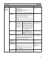
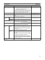
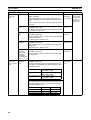
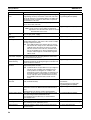
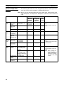
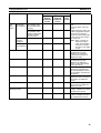
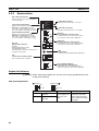
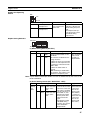
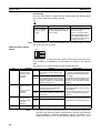
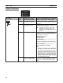
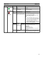
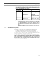
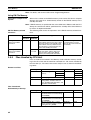
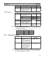
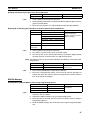
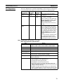
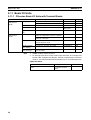
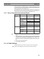
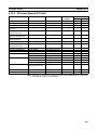
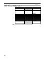
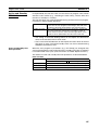
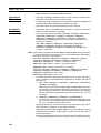
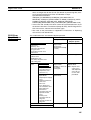
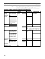
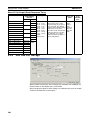
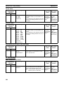
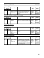
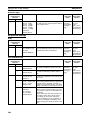
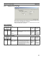
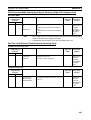
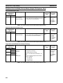
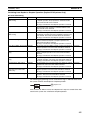
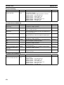
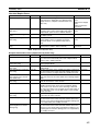
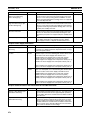
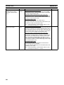
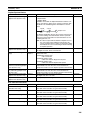
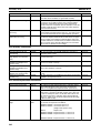
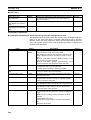
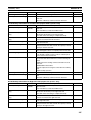
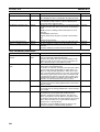
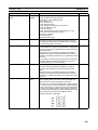
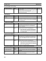
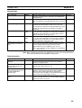
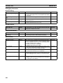
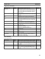
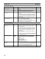
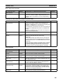
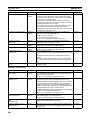
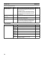
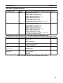
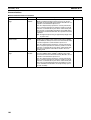
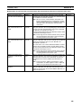
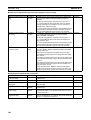
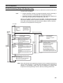
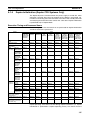
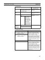
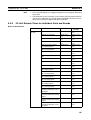
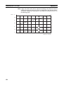
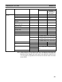
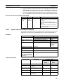
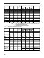
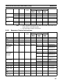
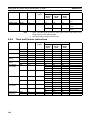
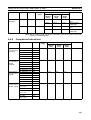
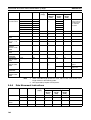
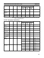
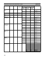
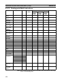
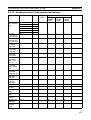
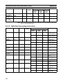
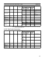
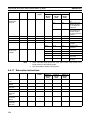
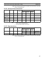
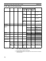
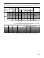
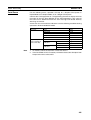
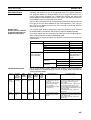
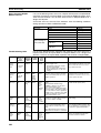
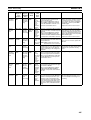
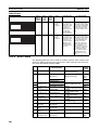
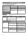
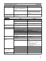
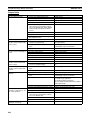
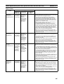
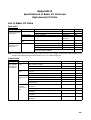
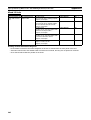
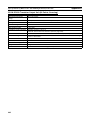
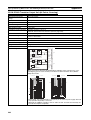
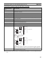
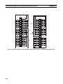
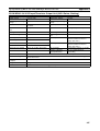
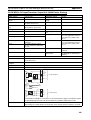
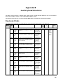
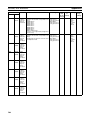
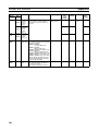
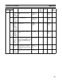
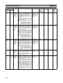
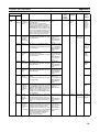
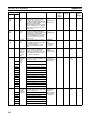
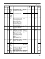
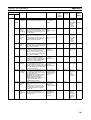
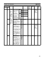
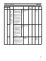
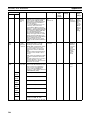
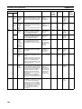
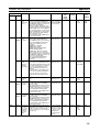
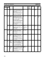
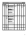
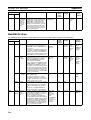
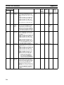
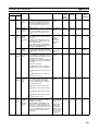
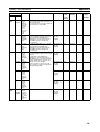
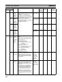
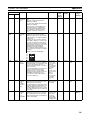
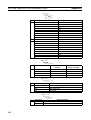
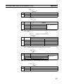
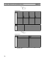
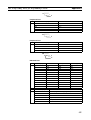
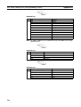
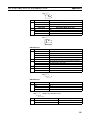
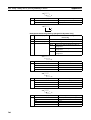
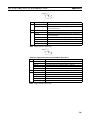
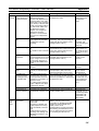
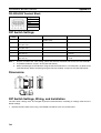
Appendix B
Auxiliary Area Allocations
Address
Words
Name
Function
Settings
Bits
Status
after
mode
change
Status at
startup
Timing
Related
flags,
settings
A406
All
PLC Setup When there is a setting error in the
0000 to 01FF
Error
PLC Setup, the location of that error hex
Location
is written to A406 in 4-digit hexadecimal. The location is given as the
address displayed on a Programming Console.
The CPU Unit will continue operating and the ERR/ALM indicator on
the front of the CPU Unit will flash.
(A406 will be cleared when the
cause of the error is eliminated.)
Cleared
Cleared
When
error
occurs
A40210
A407
A40700
to
A40712
Too Many
I/O Points,
Details
When there are too many I/O, CPU 0000 to 1FFF
Unit operation will stop, the ERR/
hex
ALM indicator on the front of the
CPU Unit will light, and one of the
following values will be stored here.
The total number of I/O points will be
written here if the capacity of the
CPU Unit is exceeded.
The number of Racks will be written
here when the number of Expansion
I/O Racks exceeds the maximum.
Number of interrupt input points
when there are more than 32 (Single
CPU Systems only)
(These bits will be cleared when the
error is cleared.)
Cleared
Cleared
When
error
occurs
A40111,
A40713
to
A40715
A40713
to
A40715
Too Many
I/O Points,
Cause
The 3-digit binary value of these bits
indicates the cause of the Too Many
I/O Points Error and shows the
meaning of the value written to bits
A40700 to A40712.
(These bits will be cleared when the
error is cleared.)
Cleared
Cleared
When
error
occurs
---
A40800
to
A40807
Basic I/O
Unit Error,
Slot Number
When an error has occurred in a
00 to 09 hex
Basic I/O Unit, A40212 will be
(Slots 0 to 9)
turned ON and the slot number
where the error occurred will be written here in binary.
(These bits will be cleared when the
error is cleared.)
Cleared
Cleared
---
A40212
A40808
to
A40815
Basic I/O
Unit Error,
Rack
Number
When an error has occurred in a
00 to 07 hex
Basic I/O Unit, A40212 will be
(Racks 0 to 7)
turned ON and the Rack number
where the error occurred will be written here in binary.
The CPU Unit will continue operating and the ERR/ALM indicator on
the front of the CPU Unit will flash.
(These bits will be cleared when the
error is cleared.)
Cleared
Cleared
---
A40212
A409
A40900
to
A40907
Expansion I/O
Rack
Number
Duplication Flags
The corresponding flag will be
turned ON when an Expansion I/O
Rack’s starting word address was
set from a Programming Device and
two Racks have overlapping word
allocations or a Rack’s starting
address exceeds CIO 0901. Bits 00
to 07 correspond to Racks 0 to 7.
(The corresponding flag will be
cleared when the error is cleared.)
ON: Error
OFF: No error
Cleared
Cleared
---
---
A410
A41000
to
A41015
CPU Bus
Unit Number Duplication
Flags
The Duplication Error Flag (A40113)
and the corresponding flag in A410
will be turned ON when an CPU Bus
Unit’s unit number has been duplicated. Bits 00 to 15 correspond to
unit numbers 0 to F.
CPU Unit operation will stop and the
ERR/ALM indicator on the front of
the CPU Unit will light.
ON: Duplication
detected
OFF: No duplication
Cleared
Cleared
---
A40113
A408
532
000: Too many
I/O total
001: Too many
interrupt input
points
101: Too many
Racks