1
Version 1.0
Produced in April. 2000
R
Sharp Programmable Controller
NEW
Satellite
JW50H/70H/100HModule name
Module name
Ethernet module
JW-51CM
User’s Manual
Thank you for purchasing the Ethernet module (JW-51CM) for the SHARP programmable controller
JW50H/70H/100H.
Read this manual thoroughly to completely familiarize yourself with the operation.
Keep this manual for future reference. We are confident that this manual will be helpful whenever you
encounter a problem.
Make sure to read the following manuals for JW-51CM and JW50H/70H/100H together with this manual.
JW-51CM
User’s manual (this manual)
JW50H/70H/100H control module
User’s manual - Hardware version
Programming manual
Note
· This manual is written with the utmost care.Should you have any questions or inquires, please
feel free to contact one of our dealers, or our service department.
· No part of this manual may be reproduced in any form without permission of SHARP corporation.
· The contents of this manual are subject to change without prior notice.
* Ethernet is a trademark of the Xerox Corporation.
Safety Precautions
Read this manual and attached documents carefully before installation, operation, maintenance and
checking in order to use the machine correctly. Understand all of the machine knowledge, safety
information, and cautions before starting to use. In this instruction manual, safety precautions are ranked
into "danger" and "caution" as follows.
Danger
: Wrong handling may possibly lead to death or heavy injury.
Caution
: Wrong handling may possibly lead to medium or light injury.
Even in the case of
Caution , a serious result may be experienced depending on
the circumstances. Anyway, important points are mentioned. Be sure to observe them
strictly.
The picture signs of prohibit and compel are explained below.
: It means don’ts. For example, prohibition of disassembly is indicated as (
: It means a must. For example, obligation of grounding is indicated as (
1)
).
).
Installation
Caution
• Use in the environments specified in the user's manual.
Electric shock, fire or malfunction may be caused when used in the environments of high
temperature, high humidity, dusty or corrosive atmosphere, vibration or impact.
• Install according to the user's manual.
Wrong installation may cause drop, breakdown, or malfunction.
• Never admit wire chips or foreign matters.
Or fire, breakdown or malfunction may be caused.
2)
Wiring
Compel
• Be sure to ground for programmable controller.
Unless grounded, electric shock or malfunction may be caused.
Caution
• Connect the rated power source.
Connection of a wrong power source may cause a fire.
• Wiring should be done by qualified electrician.
Wrong wiring may lead to fire, breakdown or electric shock.
3)
Use
Danger
• Don’t touch the terminal while the power is being supplied or you may have an electric shock.
• Assemble the emergency stop circuit and interlock circuit outside of the programmable
controller. Otherwise breakdown or accident damage of the machine may be caused by the
trouble of the programmable controller.
Caution
• Change of program durung operation, or "Run" or "stop" during operation should be done
with particular care by confirming safety. Misoperation may lead to damage or accident of
the machine.
• Turn on the power source in the specified sequence. Turning ON with wrong sequence may
lead to machine breakdown or accident.
4)
Maintenance
Prohibit
• Don’t disassemble or modify the modules.
Or fire, breakdown or malfunction may be caused.
Caution
• Turn OFF the power source before detaching or attaching the module.
Or electric shock, malfunction or breakdown may be caused.
Ethernet module JW-51CM
■ User’s Manual
Chapter 1: Outline
Chapter 2: Handling Precautions
Chapter 3: System Configuration
Chapter 4: Name and Function of Each Part
Chapter 5: Installation/Wiring
Chapter 6: Outline of Function
Chapter 7: Computer Link Function
Chapter 8: Send/Receive Functions
Chapter 9: Routing Function
Chapter 10: Errors and Correction
Chapter 11: Network Parameter
Chapter 12: Sample Program
Chapter 13: Specifications
Index
Table of contents
Safety Precaution
Chapter 1: Outline ........................................................................................................... 1·1
(1) Features .............................................................................................................................................. 1·1
(2) Software system .................................................................................................................................. 1·1
Chapter 2: Handling Precautions .................................................................................. 2·1
(1)
(2)
(3)
(4)
(5)
Installation .......................................................................................................................................... 2·1
Wiring ................................................................................................................................................. 2·1
Treatment ........................................................................................................................................... 2·1
Static electricity ................................................................................................................................... 2·1
Cleaning ............................................................................................................................................. 2·1
Chapter 3: System Configuration .................................................................................. 3·1
Chapter 4: Name and Function of Each Part ................................................................ 4·1
Chapter 5: Installation/Wiring ............................................................................. 5·1 to 5·6
5-1 Installing an Ethernet cable ................................................................................................................ 5·1
[1] Equipment layout ............................................................................................................................ 5·1
[2] Wiring .............................................................................................................................................. 5·1
5-2 Installation ........................................................................................................................................... 5·2
[1] Installation of cable for option module ............................................................................................ 5·2
[2] Installation of JW-51CM .................................................................................................................. 5·3
5-3 Connection method ............................................................................................................................. 5·3
[1] When connecting to a 10BASE5 ..................................................................................................... 5·4
[2] When connecting to a 10BASE-T ................................................................................................... 5·6
Chapter 6: Outline of Function ........................................................................... 6·1 to 6·7
6-1 Computer link function ........................................................................................................................ 6·1
6-2 Send/receive function ......................................................................................................................... 6·2
6-3 Network parameter settings ................................................................................................................ 6·3
Chpater 7: Computer Link Function ................................................................. 7·1 to 7·57
7-1 Basic format of computer link commands ........................................................................................... 7·1
[1] Communication format .................................................................................................................... 7·1
[2] Memory address expression format ................................................................................................ 7·2
[3] Execution condition ......................................................................................................................... 7·2
[4] Table of commands ......................................................................................................................... 7·3
7-2 Descriptions of each command .......................................................................................................... 7·4
7-3 Standard buffers ............................................................................................................................... 7·23
[1] How to specify a standard buffer .................................................................................................. 7·23
[2] Parameter setting .......................................................................................................................... 7·25
[3] Standard buffer information storage area ..................................................................................... 7·26
[4] Error processing when accessing standard buffers ...................................................................... 7·26
[5] Description of commands used with standard buffers .................................................................. 7·27
7-4 Ring buffer ........................................................................................................................................ 7·31
[1] How to use the ring buffer ............................................................................................................. 7·31
[2] Operation of the ring buffer ........................................................................................................... 7·34
[3] Parameter setting .......................................................................................................................... 7·38
[4] Ring buffer information storage area (in data memory) ................................................................ 7·39
[5] Error processing when accessing ring buffers .............................................................................. 7·39
[6] Description of commands used with ring buffers .......................................................................... 7·40
[7] An example using the ring buffer .................................................................................................. 7·48
7-5 Computer link error code table ......................................................................................................... 7·53
7-6 Command execution completion information .................................................................................... 7·54
[1] Setting the parameters.................................................................................................................. 7·54
[2] Command execution completion information ................................................................................ 7·54
7-7 Time interval required for communication ......................................................................................... 7·55
7-8 Two-layer communication with satellite net ...................................................................................... 7·56
Chapter 8: Send/Receive Functions ................................................................. 8·1 to 8·10
8-1 Instruction system ............................................................................................................................... 8·1
[1] Source/destination address and channel ........................................................................................ 8·1
[2] SEND/RECEIVE instructions operation .......................................................................................... 8·3
[3] Error recovery ................................................................................................................................. 8·7
[4] Other notes ..................................................................................................................................... 8·7
8-2 Data memory starting system ............................................................................................................. 8·8
[1] System ............................................................................................................................................ 8·8
[2] Parameter setting ............................................................................................................................ 8·8
[3] Communication information storage area ....................................................................................... 8·9
[4] Other notes ..................................................................................................................................... 8·9
[5] Program example for data memory starting system ..................................................................... 8·10
Chapter 9: Routing function ................................................................................ 9·1 to 9·3
[1] Create a default router .................................................................................................................... 9·1
[2] Create a customized routing table .................................................................................................. 9·2
Chapter 10: Errors and Correction ................................................................. 10·1 to 10·4
10-1 Connection status monitor ................................................................................................................ 10·1
10-2 Settings for the retransmission timeout time ..................................................................................... 10·2
10-3 Settings for Keepalive ....................................................................................................................... 10·2
10-4 Troubleshooting ................................................................................................................................ 10·3
Chapter 11: Network Parameter ..................................................................... 11·1 to 11·10
11-1 Table of parameter ............................................................................................................................ 11·1
11-2 Setting procedure of parameters ....................................................................................................... 11·7
[1] Setting procedures using the JW-14PG ........................................................................................ 11·8
[2] Setting procedures using the JW-50SP ...................................................................................... 11·10
Chapter 12: Sample Program ........................................................................ 12·1 to 12·10
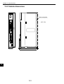
Chapter 13: Specifications .............................................................................. 13·1 to 13·2
13-1 General specifications .................................................................................................................... 13·1
13-2 Communication specifications ........................................................................................................ 13·1
13-3 Outside dimensions ........................................................................................................................ 13·2
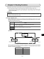
Chapter 1: Outline
The JW-51CM Ethernet module (or just “this module”) is an interface module used to connect the JW50H/70H/
100H programmable controller (or “PC”) to an *Ethernet network. Installing this module in the JW50H/70H/
100H will allow you to exchange data between host computers on Ethernet networks and LANs.
* Ethernet is a trademark of the Xerox Corporation.
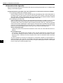
(1) Features
1 Both TCP/IP and UDP/IP protocols are available.
2 This module uses the same command format as used by Sharp’s PC computer link functions. It
allows the host computer to access PCs.
3 Data communication is possible between host computers in an Ethernet network and PCs in a
satellite network spanning two hierarchic layers.
4 This module supports the 10BASE5 and 10BASE-T interface. (Use either of the two.)
5 The JW-51CM is equipped with eight individual ports. Each port can make a separate connection.
6 Communication between PCs is possible by using the send/receive functions.
7 Using the subnet mask routing function, the JW-51CM can communicate with a large network
system using a router.
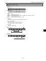
(2) Software system
JW50H/70H/100H series CU
Computer link function
JW-50CUH
JW-70CUH
JW-100CUH
Send/receive function
TCP
UDP
JW-51CM
IP
ICMP
ARP
Ethernet
10BASE5
10BASE-T
· TCP (Transmission Control Protocol)
TCP is a method used for communication after establishing a connection with a target node. It
offers a highly reliable communication environment, such as with control orders and automatic
retransmission if an error occurs.
· UDP (User Datagram Protocol)
UDP is a method to communicate without first establishing a connection with a target node. It
transmits data by assigning a target name to each transmission. If the data is not received by the
target node, the JW-51CM will not retransmit the data, as is the case in the TCP mode.
· IP (Internet Protocol)
In this method, the JW-51CM communicates with the target node in units called datagrams.
· ICMP (Internet Control Message Protocol)
ICMP is a protocol used to assist IP operations.
· ARP (Address Resolution Protocol)
This protocol obtains MAC addresses (Ethernet physical address) derived from the connected
nodes IP addresses.
· Ethernet
The JW-51CM can handle the frame format of Ethernet version 2.
1·1
1
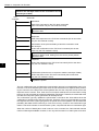
Chapter 2: Handling Precautions
(1) Installation
• Do not install or store the JW-51CM in the following conditions.
1 Direct sunlight
2 Ambient temperature exceeding the range of 0 to 55 ˚C (Storage temperature :-20 to 70 ˚C)
3 The relative humidity exceeding the range of 35 to 90%.
4 Sudden temperature changes which may cause condensation
5 Corrosive or inflammable gas
6 Vibration or hard jolts
• Prior to installing or detaching the JW50H/70H/100H, make sure to turn OFF the power supply to
the PCs.
• All screws must be tightened firmly.
• The minimum distance between transceivers is specified in the regulations. (2.5 m when the
10BASE5 is used.) When connecting devices, be sure to maintain these minimum distances.
Cables used for 10BASE5 systems have marks every 2.5 m. Position each transceiver directly
on one of these marks.
• Mount the transceivers on electrically insulated objects, such as a wooden mounting block.
(2) Wiring
• Separate the data transmission cables from power cables (less than 60 cm).
• Do not run cables near any noise generating source.
• Terminating resistances are required for both ends of the coaxial cable. Make sure to install the
specified terminating resistances.
• Use the 10BASE-T cable with a shield when installing a 10BASE-T system.
• Use an isolation shield transformer for a power supply to the hub.
• We recommend keeping the transceiver cable to 2 m or less.
(3) Treatment
• For ventilation, holes are provided in the cabinet to prevent a temperature rise. Do not block the
ventilation holes. Good ventilation is necessary.
• Never allow a liquid such as water and chemical solution and a metallic object like a copper wire
inside the JW-51CM to avoid a possible hazard. Otherwise, it may be a cause of machine
trouble.
• When a trouble or abnormal condition such as overheat, fume, or smoke is met, stop the operation immediately, and call your dealer or our service department.
(4) Static electricity
• In extremely dry circumstances, the human body may have excessive static current. This excessive static current may damage parts in the JW-51CM’s PC board. Therefore, prior to accessing
the JW-51CM, touch your hand to a grounded piece of metal to discharge the static current in
your body.
(5) Cleaning
• Use a clean, dry cloth when cleaning the JW-51CM. Do not use volatile chemicals such as
thinner or alcohol as it may result in deformation and color fading.
2·1
2
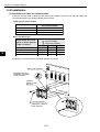
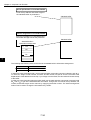
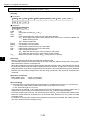
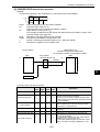
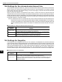
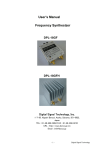
Chapter 3: System Configuration
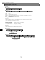
[Connection example]
JW-51CM
JW50H/70H/100H
Host computer
10BASE-T twisted pair cable
(max. 100 m)
JW20H
JW30H
JW50H/70H/100H
J W -2 5 5 C M
CM SD RD12V
T ER FT
S7 S6 S5 S4 S3 S2 S1 S0
ON SHIELD
OFF
FG
JW-255CM
Hub
JW-51CM
Transceiver
cable
Hand-held
programmer
JW-14PG
Ladder software
Max. number of stations is 100.
JW-50SP
Terminator
10BASE5 coaxial cable
(Yellow cable)
Transceiver
Coaxial cable segment (max. 500 m)
Note: Coaxial cable, transceiver, transceiver cable, 10BASE-T twisted pair cable, and terminater, etc.
should be prepared by user.
3·1
3
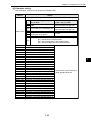
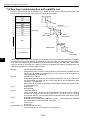
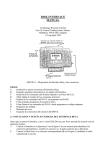
Chapter 4: Name and Function of Each Part
JW-51CM
1 LED indicator
COMM
SD
RD
DC12V
TEST
2 Connector
for programmer
01234
567
89
SW3
PROGRAMMER
ERROR
FAULT
S0
S1
S2
S3
S4
S5
S6
S7
8 SW3
(Default: 0)
3 Connector
for 10BASE5
7 SW2
(Default: ON)
10B5
4
4 Connector
for 10BASE-T
10B-T
5 12 VDC
power supply
input terminal
6 Reset SW
OFFON
SW2
Name
Function
Display panel
1
2
3
4
5
6
Indicates this module s operation status by turning the LED ON and OFF.
COMM
Lights while operating. Is OFF when operation is stopped.
SD
Blinks when the JW-51CM is transmitting data.
RD
Blinks when the JW-51CM is receiving data.
12 VDC
Lights when the JW-51CM is receiving 12 VDC power.(Only when using 10BASE5.)
TEST
Lights when the JW-51CM is in the test mode.
ERROR
Lights when a parameter setting error occurs.
FAULT
Lights when an error occurs in this module.
S0 to S7
Programmer cable
Display connection status monitor flag.
Plug in the cable assembly connector in order to connect the JW-14PG pro-
connector
grammer to this module. The JW-14PG is used to set this module s parameters.
10BASE5 cable connector
10BASE-T cable connector
12 VDC power supply input
terminal
sure to slide the lock securely to the lock position.
Connects 10BASE-T twisted pair cable.
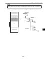
When using 10BASE5, the DC input terminal used to supply the power to the
transceiver. Use a connecting cable (accessory) and supply power from a comThis switch is only for use by our service personnel. The user should never
Reset switch
SW2
Connect the 10BASE5 transceiver cable here. After connecting the cable, make
mercial power supply. Also use 0.5 A or more power with 12 VDC –5%.
press this switch.
ON
7
12V IN
(+)
(-)
FG
RESET
The cable shield attached to 10BASE-T and 10BASE5 connectors are connected to the FG (base) of the JW-51CM.
The cable shield attached to 10BASE-T and 10BASE5 connectors are not con-
OFF nected to the FG (base) of the JW-51CM.
- Separately connection the FG line on the 12VDC connector to the ground.
8
SW3
Always set to 0.
Note: Only a 10BASE5 or 10BASE-T system can be used for communication. (Use of both types at the same time is not allowed.)
4·1
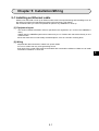
Chapter 5: Installation/Wiring
Chapter 5: Installation/Wiring
5-1 Installing an Ethernet cable
Workers who will install or hook up an Ethernet cable must have special training and knowledge, such as
the safety procedures and standards required by this technology (JIS X5252).
We recommend that you contact a specialist for perform any installation or hook up.
[1] Equipment layout
· The minimum distance between nodes is specified in the regulations. (2.5 m when the 10BASE5 is
used.)
Cables used for 10BASE5 systems have marks every 2.5 m. Position each transceiver directly on one
of these marks.
· Mount the transceivers on electrically insulated objects, such as a wooden mounting block.
[2] Wiring
· Separate the data transmission cables from power cables.
· Do not run cables near any noise generating source.
· Both ends of the coaxial cable must be terminated with a termination resistance. Make sure to install
termination resistance on each end.
5
5·1
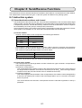
Chapter 5: Installation/Wiring
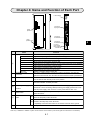
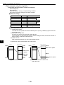
5-2 Installation
[1] Installation of cable for option module
Install the optional cable on the basic rack panel that installed JW-51CM. The optional cables and
corresponding basic rack panels available are as follows.
· Cable type for option module
Cable for option module
ZW-2CC
ZW-4CC
ZW-6CC
Maximum number of JW-51CM
that can be installed
2
4
6
· Basic rack panel type
Model name of the rack
panel on which optional
cable is installed
5
Cable for option module
( : Can be installed
: Cannot be installed)
ZW-2CC
ZW-4CC ZW-6CC
JW-4BU
JW-6BU
JW-8BU
JW-13BU
[Example] In case that install a rack panel JW-4BU to ZW-2CC
Rack panel JW-4BU
Pay attention to the
installation orientation
of the connector.
Cable for
option module
ZW-2CC
6 securing screws
(Attached to cable for
option module)
5·2
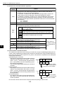
Chapter 5: Installation/Wiring
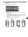
[2] Installation of JW-51CM
Attach the rack panel using the two attachment screws.
Before installation or removal, make sure to shut OFF the power supply to the PC.
[Example] Install on rack panel JW-4BU
Module
Rack panel
5
When the optional cable
ZW-2CC is connected.
Philips screwdriver
This module can be installed in any one of the optional slots.
Be careful not to bend the connector pins on the module by applying too much force to them.
Optional slots have each port numbers. When an error occurs, the JW-51CM stores the port number
corresponding to the error occurred module into system memory #050 in the PC.
This is applied only error code 53: Optional error.
(JW-13BU)
2 3 4 5 6 7
Control module
Port number
5·3
Chapter 5: Installation/Wiring
5-3 Connection method
This paragraph describes how to connect the JW-51CM to a 10BASE5 or 10BASE-T system.
Only a 10BASE5 or 10BASE-T system can be used for communication. (Use of both types at the same
time is not allowed.)
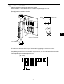
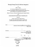
[1] When connecting to a 10BASE5
Connect the transceiver cable and power supply to the JW-51CM
(1) Connecting the transceiver cable
Slide lock
Locking post
①
↑↓
③
②
10BASE5 connector
5
Locking post
Transceiver cable
1 Slide the lock on the 10BASE5 connector (on the JW-51CM) up.
2 Insert the connector so that the two locking posts on the cable connector match the holes
on the slide lock.
3 Slide the lock down to lock the cable connector.
5·4
Chapter 5: Installation/Wiring
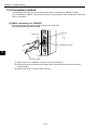
(2) Wiring the power source
When a 10BASE5 is used, 12 VDC power should be supplied to the transceiver.
Supply power to the 12 VDC power terminals using a commercial constant voltage power supply
unit.
Item
Specifications
Supply voltage
12 VDC ±5%
Current capacity
0.5 A minimum.
Ë Recommended crimping terminal
12 VDC power supply input terminal
10B5
Black cable (-)
*Fuse (0.6 A)
Red cable (+)
(+)
Twisted pair cable
12 VDC
(-)
* Use a slo-blow fuse. Housing
10B-T
12VIN
(+)
(-)
FG
RESET
Green cable
(Ground)
Cable
(Accessory: 1.5 m long cable with a connector)
Remarks
· Use a power supply that is dedicated for use by the JW-51CM.
· Do not reverse the positive and negative connections to the power terminals. Reversing the
polarity may damage the JW-51CM.
5·5
5
Chapter 5: Installation/Wiring
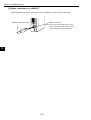
[2] When connecting to a 10BASE-T
Insert the twisted pair cable T connector into the 10BASE-T connector on the JW-51CM.
10BASE-T twisted pair cable
10BASE-T connector
Note: Do not connect the cable to the 12 VDC
power input terminal. Otherwise, you cannot communicate with the 10BASE-T.
5
5·6
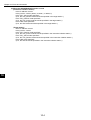
Chapter 6: Outline of Function
Chapter 6: Outline of Function
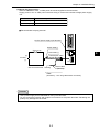
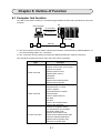
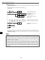
6-1 Computer link function
The data can be read or written to a connected programmable controller with commands from the host
computer.
PC
Host computer
1 Command
2 Response
JW-51CM
Ethernet
1 The host computer instructs station number/communication contents/memory address/data etc. of
the communicating station as a “command.”
2 The “command” receiving station processes this data and returns the result as “response.”
The command contains three types: read, write, and control commands.
Type
Read command
Write command
Control command
Function
Monitor relay
Monitor timer/counter current value
Monitor the register
Read program memory
Read system memory
Read date
Read time
Read out the standard buffer
Read out the ring buffer
Set/reset relay
Set/reset timer or counter
Write to register
Write same data to register
Write program
Write to system memory
Set date
Set time
Write to the standard buffer
Write to the ring buffer
Monitor PC operation status
PC stop/release stop operation
Set write enable mode
Monitor write enable mode
Read out the standard buffer data
Write the standard buffer data
Read out the ring buffer data
Write the ring buffer data
6·1
6
Chapter 6: Outline of Function
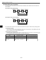
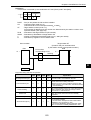
6-2 Send/receive function
The send/receive function allows the JW-51CM to send data to other stations and receive data from
other stations.
[An example of the send function]
Station 00 Station 01 Station 02 Station 03
Request to write
Response
[An example of the receive function]
Station 00 Station 01 Station 02 Station 03
Request to read
Response
6
The send/receive functions can use either the data instruction system or data memory starting system.
(1) Instruction system
The instruction system uses the application instructions F-202 (OPCH), F-204 (SEND), and F-205
(RCV), available with the JW50H/JW70H/JW100H.
(2) Data memory starting system
The data memory starting system places the target station No., the number of transmission bytes
etc. in the data memory (communication information storage area).
Item
Instruction system
Number of channels
Number of data bytes
4
256 bytes max. in one instruction
Starting from channel 0, 6000(H),
6001(H), 6002(H), and 6003(H) in
order.
Port used
6·2
Data memory starting system
1
1024 bytes max.
6008(H)
Chapter 6: Outline of Function
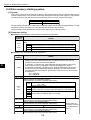
6-3 Network parameter settings
The following items are set for use as network parameters in the EEPROM.
These parameters are read when the JW-51CM starts up, and they control the details of each operation.
1 IP address, subnet mask
2 Method for opening each type of connection (TCP_Passive/TCP_Active/UDP) and port No. to
use.
3 Address settings for the send/receive functions
4 Settings related to the specified buffer command
5 Settings related to the ring buffer command
6 Settings for routing
7 Settings related to the connection status flag
8 Settings related to the completion information of the computer link command
After the power is turned ON, the JW-51CM will open each channel according to the details stored in the
EEPROM. The method for opening a channel varies with the parameter settings, as shown below.
(1) TCP_Passive
The port which is opened after selecting the TCP_Passive mode waits for a connection from the other
station.
This mode can be used in communication target stations with a computer link function or when the
send/receive function is selected.
Connections opened in the TCP_Passive mode cannot be disconnected by the module using that
mode. The station opened in the TCP_Passive cannot open or disconnect any connection. However,
it can start instructions of the send/receive function. The port which is under opening the connection
cannot communicate with other stations.
(2) TCP_Active
The TCP_Active mode is used to open connections to other stations. This mode can be used with a
command triggering station using the send/receive functions. By using this method, the connection to
another station can also be broken. While a connection is open, the port cannot communicate with
other stations.
(3) UDP
The UDP mode is a mode not to open any connection. It can be selected by the computer link or with
send/receive functions. The UDP is less reliable than TCP, since it does not allow confirmation of the
data receipt (checking to see the data was received by the target station) at the data transmission
protocol stage.
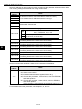
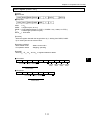
[Example]
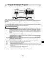
Set the open method used for the communication between PC1, PC2, and the host device A.
1 Host device A communicates with PC1 using the TCP over the computer link.
2 PC1 communicates with PC2 using the send command (TCP_Passive).
Host
device
A
1
PC1
PC2
2
TCP_Passive
TCP_Active
6·3
TCP_Passive
6
Chapter 6: Outline of Function
Set the IP address and open method for each connection at the parameter addresses shown below.
The following settings are essential when using the JW-51CM.
Parameter
address
0000
0001
0002
0003
0004
0005
0006
0007
Details
IP addresses inside the JW-51CM (0003 is used by the host.)
For the details about IP addresses, see the next page.
Subnet mask: See page 6.6
Settings for connection 0: See page 6.7
Open method 00(H): TCP_Passive
0100
80(H): TCP_Active, 01(H): UDP
0100 to 0103
0101 00
0102 JW-51CM port number
0103 (0102 as low, 0103 as high)
6
Settings for connection 1
0104 to 0107 (The setting details are the same as for connection 0.)
Settings for connection 2
0110 to 0113
(The setting details are the same as for connection 0.)
Settings for connection 3
0114 to 0117 (The setting details are the same as for connection 0.)
Settings for connection 4
0120 to 0123 (The setting details are the same as for connection 0.)
Settings for connection 5
0124 to 0127
(The setting details are the same as for connection 0.)
Settings for connection 6
0130 to 0133 (The setting details are the same as for connection 0.)
Settings for connection 7
0134 to 0137 (The setting details are the same as for connection 0.)
Set the communication start/halt conditions in the parameter shown below.
Parameter
address
3777
Details
Communication start switch
00(H): Halts communication
01(H): Checks the parameter, checks the BCC, and starts operation
08(H): Initializes the parameters (all parameters = 00(H))
80(H): Checks the parameters, creates a BCC, writes it to EEPROM,
and halts operation
81(H): Checks the parameter, creates a BCC, writes it to EEPROM,
and starts operation
(If the operation is resumed, this parameter will change to 01(H).)
For the details about other parameters, see Chapters 7, 8, and 11.
6·4
Chapter 6: Outline of Function
Ë TCP and UDP
TCP is a method used for communication after establishing a connection with a target node. It
offers a highly reliable communication environment, with control orders and automatic retransmission if an error occurs.
The TCP can be though as similar to the way a telephone work, due to its characteristics. (If you
call someone, you can only to speak to that party until you hang up.)
UDP is a method to used for communication without needing to first establish a connection with a
target node. It transmits data by assigning a target name to each transmission. If the data is not
received by the target node, the JW-51CM will not retransmit the data, as is the case in the TCP
mode.
The UDP can be compared to writing a letter, due to its characteristics. (You send a letter after
writing the address of a single recipient on the envelop.)
Ë IP addresses
IP addresses are used to distinguish devices, which are communicating on a single Ethernet network. They are 32 bits long.
The IP address consists of the net ID, indicating the network device No., and the host ID, indicating
the node No. inside the network. They are three classes of IP address, according to the number of ID
bits used.
0
8
31
Class A
ID
0 Network
(7-bit)
Host device ID (24-bit)
0
16
Class B
1 0
Network ID (14-bit)
31
24
0
Class C
1 1 0
6
Host device ID (16-bit)
Network ID (21-bit)
31
Host device ID (8-bit)
The numbers of network devices and hosts that can be identified, depend on the class of IP address
used.
Class Number of devices in the network Number of host devices
Class A
Small scale
More than 65536
Middle scale
256 to 65535
Class B
Large scale
Less than 255
Class C
The 32 bits data in the address are divided into 8 bit groups, expressed in decimal notation, and
linked together using periods.
e.g.: The following is a class C IP address: 192.9.200.2.
11000000 00001001 11001000 00000010
Use the same net ID for devices in the same network. Specify an IP address that is different from the
addresses for all other devices.
Enter the IP address in the parameter addresses (0000 to 0003) in the module.
In case of the example shown above, store the IP address in the parameter addresses as follows.
Parameter
address
0000
0001
0002
0003
Set value (D)
192
9
200
2
6·5
Chapter 6: Outline of Function
Ë Subnet mask
IP addresses are expressed using two types of identifiers (an IP address (see the NOTE) and a
subnet mask address). The subnet mask indicates the length of the network address (network ID)
contained in the bits of the IP address. With a subnet mask, the IP addresses in the each class can
be used to divide a conceptual network into multiple physical networks (subnets). The subnet mask
addresses should be allocated sequentially, starting with the upper most bit.
NOTE: The IP address described here refers to an IP address without a subnet mask.
[Subnet mask examples]
The example shown below describes a subnet mask set to 255.255.255.0 with a class B IP
address of 172.20.100.52.
When to indicate 170.20.100.52 in binary notation
IP address : 10101100 00010100 01100100 00110100
(Underlined bits are the class B network ID.)
Subnet mask : 11111111 11111111 11111111 00000000
10101100 00010100 01100100 00110100
(Underlined bits indicate a network ID that is extended with a subnet mask.)
6
When setting the ID using the above subnet mask
Network ID : 10101100 00010100 01100100 00000000 (172.20.100.0)
Host ID
: 10101100 00010100 01100100 00000001 (172.20.100.1)
to
to
10101100 00010100 01100100 11111110 (172.20.100.254)
(All underlined bits are for a network ID that is set using a subnet mask.)
Broadcast
: 10101100 00010100 01100100 11111111 (172.20.100.255)
address
(All underlined bits are for a network ID that is set using a subnet mask.)
· A broadcast address is used to transmit packets to all hosts connected to the same
network.
Nodes located in sub-nets are given different IDs for communcation. To communicate with each
other, a router is required. => See page 9-3.
Assign the subnet mask address by placing it in parameter addresses 0004 to 0007 in this module.
In the case of the example shown above, the subnet mask bytes in the parameter are assigned as
follows:
Parameter address
Set value(D)
0004
255
0005
255
0006
255
0007
0
If all of the parameter addresses from 0004 to 0007 are set to 0, it means “a subnet is not used.” This
means that the specific subnet mask address assigned is equal to the bit length of the particular
class of network ID.
For example, when the IP address in this module is set to 192.168.150.3 (class C) and all of the
parameters for the subnet mask are set to 0, it will be equal to assigning a subnet mask of
255.255.255.0.
6·6
Chapter 6: Outline of Function
Ë Port No.
The port No. is the logical communication doorway provided in a node. The port number can be
between 1 and 65534 (a 16-bit long). No. 0 and 65535 have special meanings.
Together with the TCP and IP, the port No. is used to identify the applicable protocols. The applicable
protocols corresponding to the port No. have already been determined. (For example, the file transmission FTP is assigned to 21, and the remote terminal telnet is assigned to 23.) These are called
“Well-known ports.” The assignment of ports 1 to 1000 have already been determined.
With the JW-51CM, the port No. can be set freely in the range 1 to 65534. However, we recommend
assigning a port No. (upper value No.) that is not one of the well-known ports.
Ë Socket and connection
In the TCP and UDP connection open methods, the IP addresses and port Nos are used to specify
the destination addresses and the senders. Normally, only one value is used for the node for an IP
address. However, a parallel communication process with multiple ports is possible by opening
multiple ports inside a node. Then, each port becomes a logical doorway to a communication circuit
and is called a “socket” in the terminology used for TCP and UDP communications.
Sockets are broadly divided into two types: One type uses the TCP, and the other uses the UDP.
The TCP forms a virtual communication route by making a connection with the communication
target. This is referred to as “establishing the connection.” After the connection is established, the
socket can only communicate with this target. After the communication is complete, the devices
perform a disconnection procedure. The TCP offers highly reliable communications with special
functions, such as automatic retransmission in case of a time-out. However, the TCP has a large
overhead, since connection and disconnection procedures are required, and the module must wait
for confirmation from the target each time data is transmitted.
The UDP does not use a connection process to find a communication target. The data is transmitted
by specifying the target each time. The UDP does not retransmit the data if it is not received by the
target. Therefore, the UDP also does not need to perform any connection or disconnection procedures. However, it offers less reliability than the TCP.
6·7
6
Chapter 7: Computer Link Function
Chpater 7: Computer Link Function
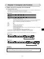
7-1 Basic format of computer link commands
[1] Communication format
A message from the host computer to the JW-51CM is referred to as a “command.” A response from the
JW-51CM to the host computer is referred to as a “response.”
The communication formats of the command and response are as follows:
Ë Command
Header (40 bytes)
c-ID
ATTR
COM
Ë Response
Header (40 bytes)
r-ID
ATTR
COM
Command Text
RSLT
Response Text
Header
: Normally, all 40 bytes are 00(H).
If you want to communicate with a satellite net using a JW-51CM to interface between
layers of hierarchical communication, you have to use an extension header.
(See “7-8 Two-layer communication with satellite net”)
c-ID
: 47(H)
r-ID
: 45(H)
ATTR
: 00(H)
COM
: Command code (See page 7·3)
RSLT
: Command execution result
Normaly terminated with 00(H)
If any byte other than 00(H) is found, an error code will be output (See “7-5” Computer
link error code table”).
If an error code is output, there is no response text.
Command Text : Command details (See “7-2 Descriptions of each command”)
Response Text : Response details (See “7-2 Descriptions of each command”)
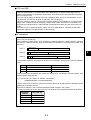
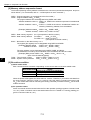
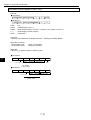
[Example] When you want to monitor the ON/OFF status of relay 04033. (See page 7·6)
■ Command
Header (40 bytes)
00
¥¥¥
00
c-ID
ATTR
COM
47
00
20
Command Text
00
File 0
03
01
03
File address
000403(8) = 0103(H)
Bit 3
Relay No. 04033
■ Response
Header (40 bytes)
00
¥¥¥
00
r-ID
45
ATTR
COM
RSLT
00
20
00
Response Text
00
File 0
03
01
File address
000403(8) = 0103(H)
03
01
Bit 3
ON
Relay No. 04033
Remarks
The maximum data length for read/write operations is 1024 bytes. In case of two-layer communication with the satellite net, however, the maximum length is 256 bytes. For the UDP, the total number
of bytes from the header to the command text must be less than 1024 bytes.
7·1
7
Chapter 7: Computer Link Function
[2] Memory address expression format
The format expressing memory address contained in the command (command text/response text) is as
shown below. ( For more details, refer to “7-2 Descriptions of each command.”)
PSEG : Program segment 8, 9 (corresponds to the file number.)
PADR : Program address 0000(H) to 7DFF(H)
The program address is to be designated using PSEG and PADR.
Address 000000 to 076777(8) : PSEG = 8, PADR is the address expressed in hexadecimal
notation.
Address 100000 to 176777(8) : PSEG = 9, PADR is the value in hexadecimal notation obtained by subtracting 100000(8) from the address.
[Example] Address 043256(8) : PSEG = 08(H), PADR= 46AE(H)
Address 153762(8) : PSEG= 09(H), PADR = 57F2(H)
DSEG : Data memory segment
DADR : Data memory address
0 to 7(corresponds to the file number.)
For SEG 0
: 0000(H) to 1FFF(H)
For SEG 1 to 7 : 0000(H) to FFFF(H)
(corresponds to the file number.)
BLOC : Bit location on the data memory 0 to 7
The register (file register) is to be designated using DSEG and DADR.
[Example] Register 09000
: DSEG = 00(H), DADR = 0800(H)
030000 of the file 1 : DSEG = 01(H), DADR = 3000(H)
7
The relay address is to be designated using DSEG, DADR, and BLOC.
The destination is made by the combination of the file address and the bit location.
[Example] Relay 07252: DSEG = 00(H), DADR = 01D5(H), BLOC = 02(H)
(bit 2 of the file 000725 (]0725))
TADA : Timer/counter number
0000(H) to 03FF(H) (0000 to 1777(8))
SADR : System memory address
0000(H) to 047F(H) (0000 to 2177(8))
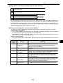
[3] Execution condition
(1) Write enable mode
Each command will be executed or depending on the current status of the write enable mode.
Write enable mode
Details
Writing to all of memory is prohibited
Mode 0
Mode 1
Writing is only enabled to data memory
Mode 2
Writing is enabled to all of memory
When the power is first applied, the JW-51CM is in “mode 0.” Therefore, if you want to write data from
the host computer, change to “mode 1 or “mode 2” using the setting command (command code
F9(H)). The current status can be read using the reading command (command code E9(H)) for the write
enable command.
(2) PC operation status
Some commands can be executed when the PC halts operation (writing programs: Command code
14(H) etc.). Other commands can be executed whether the PC is halted or is running (reading programs: Command code 04(H) etc.)
7·2
Chapter 7: Computer Link Function
[4] Table of commands
Commad code
Contents
See page
04(H)
14(H)
20(H)
23(H)
24(H)
28(H)
29(H)
30(H)
32(H)
34(H)
35(H)
38(H)
39(H)
44(H)
54(H)
68(H)
69(H)
78(H)
79(H)
A2(H)
A3(H)
B2(H)
B3(H)
E8(H)
E9(H)
F8(H)
F9(H)
Reading program
Write program
Monitoring relay
The current value monitor of the timers/counters
Monitoring register
Read from a standard buffer
Read a ring buffer
Set/reset relay
Set/reset timer/counter
Write in register
Write same data to register
Write to a standard buffer
Write to a ring buffer
Read out the system memory
Write to the system memory
Read information about a standard buffer
Read information about a ring buffer
Write information about a standard buffer
Write information about a ring buffer
Read date
Read time
Set date
Set time
Monitor PC operation status
Read out write enable mode
Halt and release halting of PC
Selecting the write enable mode
7·15
7·16
7·6
7·9
7·10
7·27
7·40
7·7
7·8
7·11
7·12
7·28
7·42
7·13
7·14
7·29
7·44
7·30
7·46
7·17
7·19
7·18
7·20
7·21
7·4
7·22
7·5
7·3
7
Chapter 7: Computer Link Function
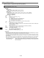
7-2 Descriptions of each command
This section describes the “COM” settings and the items thereafter of the communication formats (page
7·1).
Commands for the standard buffer are described on pages 7·27 to 7·30. Commands for the ring buffer
are described on pages 7·40 to 7·47.
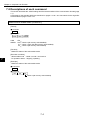
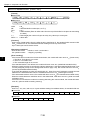
Read out write enable mode (COM=E9(H))
[Format]
Ë Commad
COM
Ë Response
COM RSLT WMOD
COM
= E9(H)
WMOD = 00(H) : Mode 0 (All memory write-disabled)
01(H) : Mode 1 (Only the data memory write-enabled)
02(H) : Mode 2 (All memory write-enabled)
[Function]
· Reads the status of the write-enable mode.
7
[Execution condition]
· Write enable mode : Mode 0, mode 1 and mode 2
· PC operation status : Stopping, operating
[Example]
· Reads the status of the write-enable mode.
Ë Command
E9
Ë Response
E9
00
02
Mode 2 (All memory write-enabled)
7·4
Chapter 7: Computer Link Function
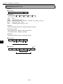
Selecting the write enable mode COM = F9(H)
[Format]
Ë Command
COM WMOD
Ë Responce
COM RSLT
COM
= F9(H)
WMOD = 00(H) : Mode 0 (All memory write-disabled)
01(H) : Mode 1 (Only the data memory write-enabled)
02(H) : Mode 2 (All memory write-enabled)
[Function]
· Selecting the write enable mode.
[Execution condition]
· Write enable mode : Mode 0, mode 1 and mode 2
· PC operation status : Stopping, operating
[Example]
· Set the write enable mode to mode 2 (Writing is enable to all of memory).
Ë Command
F9
02
Mode 2 (All memory write-enabled)
Ë Response
F9
00
7·5
7
Chapter 7: Computer Link Function
Monitoring relay (COM = 20(H))
[Format]
Ë Command
COM DSEG DADRL DADRH BLOC
Ë Response
COM
COM
DSED
DADRL, H
BLOC
DATA
RSLT DSEG DADRL DADRH BLOC DATA
= 20(H)
= Segment (00(H) to 07(H))
= Byte address (0000(H) to FFFF(H), if DSEG = 00(H), 0000(H) to 1FFF(H))
= Bit position (00(H) to 07(H))
= Read data (00(H): OFF, 01(H): ON)
[Function]
· Read the bit data (relay) shown in DSEG, DADR, and BLOC.
[Execution condition]
· Write enable mode : Mode 0, mode 1 and mode 2
· PC operation status : Stopping, operating
[Example]
· Monitor the ON/OFF status of relay number 04033.
Ë Command
20
7
00
File 0
03
01
03
Bit 3
File address
000403(8) = 0103(H)
Relay number 04033
Ë Response
20
00
ON
00
File 0
03
01
03
File address
000403(8) = 0103(H)
01
Bit 3
Relay number 04033
7·6
Chapter 7: Computer Link Function
Set/reset relay (COM = 30(H))
[Format]
Ë Command
COM DSEG DADRL DADRH BLOC
DATA
Ë Response
COM
COM
DSED
DADRL, H
BLOC
DATA
RSLT DSEG DADRL DADRH BLOC
= 30(H)
= Segment (00(H) to 07(H))
= Byte address (0000(H) to FFFF(H), if DSEG = 00(H), 0000(H) to 1FFF(H))
= Bit position (00(H) to 07(H))
= Set/reset data (00(H): reset, 01(H): set)
[Function]
· Set/reset the relays shown in DSEG, DADR, and BLOC.
[Execution condition]
· Write enable mode : Mode 1 and mode 2
· PC operation status : Stopping, operating
[Example]
· Set relay number 07001.
Set
Ë Command
30
00
File 0
C0
01
01
File address
000700(8) = 01C0(H)
01
7
Bit 1
Relay number 07001
Ë Response
30
00
00
File 0
C0
01
01
File address
000700(8) = 01C0(H)
Bit 1
Relay number 07001
7·7
Chapter 7: Computer Link Function
Set/reset timer·counter (COM = 32(H))
[Format]
Ë Command
COM TADRL TADRH DATA
Ë Responce
COM
RSLT TADRL TADRH
COM
= 32(H)
TADRL, H = Timer·counter number (0000(H) to 03FF(H))
DATA
= Set/reset data (00(H): reset, 01(H): set)
[Function]
· Set/reset the timer/counter displayed on TADR.
[Execution condition]
· Write enable mode
· PC operation status
: Mode 1 and mode 2
: Stopping, operating
[Example]
· Set TMR0002.
Ë Command
32
02
00
01
Timer and counter
number 0002
7
Set
Ë Responce
32
00
02
00
Timer and counter
number 0002
7·8
Chapter 7: Computer Link Function
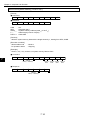
The current value monitor of the timers/counters (COM = 23(H))
[Format]
Ë Commad
COM TADRL TADRH
LL
LH
Ë Response
COM
RSLT TADRL TADRH
DATAN
LL
LH
ATTR1
...
DATA1
...
ATTRN
COM
= 23(H)
TADRL, H = Timer and counter number (0000(H) to 03FF(H))
LL, H
= Number of data to read
DATA1 to N = The current value data (read current value field of the timer and the counter)
ATTR1 to N = The attribute data of the timer and the counter
[Function]
· Reads the current values and the attributes of the timers/counters identified by the starting number
TADR and the number of data L.
· Up to 256 timers/counters can be read at a time.
· The current value data is read from the timer/counter’s current range (b0000 to xxxxx ).
· The attributes are as shown below :
00(H)
01(H)
02(H)
04(H)
08(H)
09(H)
Not in use
MD
CNT
TMR
DTMR(BCD)
DTMR(BIN)
[Execution condition]
· Write enable mode
· PC operation status
0A(H)
0B(H)
0C(H)
0D(H)
0E(H)
0F(H)
UTMR(BCD)
UTMR(BIN)
DCNT(BCD)
DCNT(BIN)
UCNT(BCD)
UCNT(BIN)
7
: Mode 0, mode 1 and mode 2
: Stopping, operating
[Example]
· Reads the current values of TMR0000 and TMR0001.
Ë Command
23
00
00
Top number of
the timer and
the counter
Ë Response
23
00
00
02
00
Number of data
00
Top number of
the timer and
the counter
02
00
Number of data
7·9
34
92
The current
value of
TMR0000
1234
78
D6
The current
value of
TMR0001
5678
08
0A
DTMR
(BCD)
UTMR
(BCD)
Chapter 7: Computer Link Function
Monitoring register COM = 24(H)
[Format]
Ë Command
COM DSEG DADRL DADRH
LL
LH
Ë Response
COM
RSLT DSEG DADRL DADRH
LL
LH
DATA1 ......
DATAN
COM
= 24(H)
DSEG = Segment (00(H) to 07(H))
DADRL, H = Byte address (0000(H) to FFFF(H), if DSEG = 00(H), 0000(H) to 1FFF(H))
LL, H
= Data length (Number of bytes)
DATA1 to N = Read data
[Function]
· Read the register data with the length shown by L, starting from DSEG, DADR.
· Up to 1024 bytes can be read at a time.
[Execution condition]
· Write enable mode
· PC operation status
: Mode 0, mode 1 and mode 2
: Stopping, operating
[Example]
· Read 4 bytes data from register 09000 to 09003.
Ë Command
7
24
00
00
08
File address
File number 0 0800(H) = 004000(8)
04
00
Data length
Top register
number 09000
Ë Response
24
00
00
00
08
File address
04
00
00
4F
32
01
Data length
File number 0 0800(H) = 004000(8)
Value at Value at Value at Value at
09000
09001 09002
09003
Top register
number 09000
7·10
Chapter 7: Computer Link Function
Write in register (COM = 34(H))
[Format]
Ë Command
COM DSEG DADRL DADRH
LL
LH
DATA1
LL
LH
......
DATAN
Ë Response
COM
RSLT DSEG DADRL DADRH
COM
= 34(H)
PSEG = Segment (00(H) to 07(H))
PADRL, H = Byte address (0000(H) to FFFF(H), if DSEG = 00(H), 0000(H) to 1FFF(H))
LL, H
= Data length (number of bytes)
DATA1 to N = Write data
[Function]
· Write the register data with the length shown by L, starting from DSEG, DADR.
· Up to 1024 bytes can be write at a time.
[Execution condition]
· Write enable mode
· PC operation status
: Mode 1 and mode 2
: Stopping, operating
[Example]
· Write 00(H), 4F(H), 32(H), and 01(H) to registers 09000 to 09003.
Ë Command
34
00
00
File number 0
08
File address
0800(H) = 004000(8)
04
00
00
00
00
File number 0
01
Value at Value at Value at Value at
09000
09001 09002
09003
Ë Response
00
32
Data length
Top register
number 09000
34
4F
08
File address
0800(H) = 004000(8)
04
00
Data length
Top register
number 09000
7·11
7
Chapter 7: Computer Link Function
Write same data to register (COM = 35(H))
[Format]
Ë Command
COM DSEG DADRL DADRH
LL
LH
DATA
LL
LH
Ë Response
COM
COM
PSEG
PADRL, H
LL,H
DATA
RSLT DSEG DADRL DADRH
= 35(H)
= Segment (00(H) to 07(H))
= Byte address (0000(H) to FFFF(H), if DSEG = 00(H), 0000(H) to 1FFF(H))
= Data length (number of bytes)
= Write data
[Function]
· Write the same data with the length shown by L, starting from DSEG, DADR.
[Execution condition]
· Write enable mode
· PC operation status
: Mode 1 and mode 2
: Stopping, operating
[Example]
· Write 4F(H) to register 19000 to 19003 (4 bytes).
Ë Command
7
35
00
00
0A
File address
File number 0 0A00(H) = 005000(8)
00
4F
Data length
Data
Top register
number 19000
Ë Response
35
04
00
00
File number 0
00
0A
File address
0A00(H) = 005000(8)
04
00
Data length
Top register
number 19000
7·12
Chapter 7: Computer Link Function
Read out the system memory (COM = 44(H))
[Format]
Ë Command
COM SEG SADRL SADRH
LL
LH
Ë Response
COM
RSLT
SEG SADRL SADRH
LL
LH
DATA1
......
DATAN
COM
= 44(H)
SEG
= Segment (08(H))
SADRL,H = System memory address (0000(H) to 047F(H))
LL,H
= Data length (number of bytes)
DATA1 to N = Read data
[Function]
· Read the system memory data with the length shown by L, starting from SEG, SADR.
[Execution condition]
· Write enable mode
· PC operation status
: Mode 0, mode 1 and mode 2
: Stopping, operating
[Example]
· Read data of system memory #204 to 207.
Ë Command
44
08
84
00
System memory
address
0084(H)=000204(8)
04
00
7
Data length
Ë Response
44
00
08
84
00
System memory
address
0084(H)=000204(8)
04
00
80
01
08
00
Data length
Value at Value at Value at Value at
#204
#205
#206
#207
7·13
Chapter 7: Computer Link Function
Write to the system memory (COM = 54(H))
[Format]
Ë Command
COM SEG SADRL SADRH
Ë Response
COM RSLT
COM
SEG
SADRL, H
LL, H
DATAL to N
LL
SEG SADRL SADRH
LH
DATA1
LL
LH
.....
DATAN
= 54
= Segment (08(H))
= System memory address (0000(H) to 047F(H))
= Data length (number of bytes)
= Write data
[Function]
· Write the system memory data with the length shown by L, starting from SEG, SADR.
[Execution condition]
· Write enable mode
· PC operation status
: Mode 2
: Stopping
[Example]
· Set 81(H), 00(H), 00(H), and 04(H) to system memory #204 to #207.
Ë Command
54
08
7
84
00
System memory
address
0084(H)=000204(8)
04
00
81
00
08
84
00
04
Data length
Value at Value at Value at Value at
#204
#205
#206
#207
Ë Response
54
00
00
System memory
address
0084(H)=000204(8)
04
00
Data length
7·14
Chapter 7: Computer Link Function
Reading program (COM = 04(H))
[Format]
Ë Command
COM PSEG PADRL PADRH
LL
LH
Ë Response
COM RSLT PSEG PADRL PADRH
COM
PSEG
PADRL,H
LL,H
DATA1 to N
LL
LH
DATA1
······
DATAN
= 04(H)
= Program segment (08(H), 09(H))
= Program address (0000(H) to 7DFF(H))
= Data length (number of words)
= Read data (2 bytes = one step)
[Function]
· Read a program with a length (number of words) shown by L, from address PSEG, PADR.
· Up to 512 words can be read at a time.
[Execution condition]
· Write enable mode
· PC operation status
: Mode 0, mode 1 and mode 2
: Stopping, operating
[Example]
· Read the contents of the program address 000000 to 000002 (file number 8)
Ë Command
04
08
00
00
03
00
Top program
address
Data length
08
00
7
Ë Response
04
00
00
Top program
address
08
03
00
Data length
00
80
Address
000000 contents
00
Address
000001 contents
B8
Address
000002 contents
Note: Inquiries concerning the bit configuration of programs cannot be accepted.
7·15
91
Chapter 7: Computer Link Function
Write program (COM = 14(H))
[Format]
Ë Command
COM PSEG PADRL PADRH
LL
LH
DATA1
.....
DATAN
Ë Response
COM
COM
PSEG
PADRL, H
LL, H
DATA1 to N
RSLT PSEG PADRL PADRH
LL
LH
= 14(H)
= Program segment (08(H), 09(H))
= Program address (0000(H) to 7DFF(H))
= Data length (number of words)
= Write data (2 bytes = one step)
[Function]
· Write a program with a length (number of words) shown by L, from address PSEG, PADR.
· Up to 512 words can be write at a time.
[Execution condition]
· Write enable mode
· PC operation status
: Mode 2
: Stopping
[Example]
· Write the contents below in program address 000000 to 000002 (file number 8).
7
Ë Command
14
08
Ë Response
14
00
00
00
03
00
Top program
address
Data length
08
00
00
Top program
address
03
00
80
Address
000000 contents
00
91
Address
000001 contents
00
Data length
Note: Inquiries concerning the bit configuration of programs cannot be accepted.
7·16
08
B8
Address
000002 contents
Chapter 7: Computer Link Function
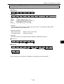
Read date (COM = A2(H))
[Format]
Ë Command
COM
Ë Response
COM
COM
Y
M
D
DW
RSLT
Y
M
D
DW
= A2(H)
= Year (express lower two digits of Westerrn year, 00(H) to 99(H))
= Month (01(H) to 12(H))
= Date (01(H) to 31(H))
= Day of week (00(H): Sunday, 01(H): Monday, 02(H): Tuesday, 03(H): Wednesday, 04(H): Thursday, 05(H): Friday, 06(H): Saturday)
[Function]
· Read date data.
[Execution condition]
· Write enable mode
· PC operation status
: Mode 0, mode 1 and mode 2
: Stopping, operating
[Example]
· Read date data.
Ë Command
A2
7
Ë Response
A2
00
97
'97
12
17
03
December
17
Wednesday
7·17
Chapter 7: Computer Link Function
Set date (COM = B2(H))
[Format]
Ë Command
COM
Y
M
M
DW
Ë Response
COM RSLT
COM
Y
M
D
DW
= B2(H)
= Year (express lower two digits of Western year in BCD. 00(H) to 99(H))
= Month (01(H) to 12(H))
= Date (01(H) to 31(H))
= Day of week (00(H): Sunday, 01(H): Monday, 02(H): Tuesday, 03(H): Wednesday, 04(H): Thursday, 05(H): Friday, 06(H): Saturday)
[Execution condition]
· Write enable mode
· PC operation status
: Mode 1 and mode 2
: Stopping, operating
[Function]
· Set date data.
[Example]
· Set data to Friday, January 23, 1998.
Ë Command
7
B2
98
01
23
05
'98
January
23
Friday
Ë Response
B2
00
7·18
Chapter 7: Computer Link Function
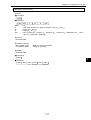
Read time (COM = A3(H))
[Format]
Ë Command
COM
Ë Response
COM
COM
H
M
S
RSLT
H
M
S
= A3(H)
= Hour (00(H) to 23(H): BCD)
= Minute (00(H) to 59(H): BCD)
= Second (00(H) to 59(H): BCD)
[Function]
· Read time data.
[Execution condition]
· Write enable mode
· PC operation status
: Mode 0, mode 1 and mode 2
: Stopping, operating
[Example]
· Read time data.
Ë Command
A3
Ë Response
A3
00
21
12
7
37
21 o'clock 12 minutes 37 seconds
7·19
Chapter 7: Computer Link Function
Set time (COM = B3(H))
[Format]
Ë Command
COM
H
M
S
CTRL
Ë Response
COM
COM
H
M
S
CTRL
ACK
=B3(H)
= Hour
(00(H) to 23(H): BCD)
= Minute (00(H) to 59(H): BCD)
= Second (00(H) to 59(H): BCD)
= Control data 00(H): Run clock
01(H): Stop clock
08(H): 30 sec. correction
[Function]
· Write time data
[Execution condition]
· Write enable mode
· PC operation status
: Mode 1 and mode 2
: Stopping, operating
[Example]
· Set time data to 18 o’clock, 10 minutes, and 20 seconds.
Ë Command
7
B3
18
10
20
00
18 o'clock 10 minutes 20 seconds Run clock
Ë Response
B3
00
7·20
Chapter 7: Computer Link Function
Monitor PC operation status (COM = E8(H))
[Format]
Ë Command
COM MODE
Ë Response
COM
COM
MODE
RSLT MODE
= E8(H)
= 00(H): Operating
01(H): Stopped operation by an instruction from other module.
02(H): Stopped operation by an instruciton from this module.
[Function]
· Monitor PC run/stop status.
[Execution condition]
· Write enable mode
· PC operation status
: Mode 0, mode 1 and mode 2
: Stopping, operating
[Example]
· Monitor PC operation status.
Ë Command
E8
Ë Response
E8
00
7
00
Operating
7·21
Chapter 7: Computer Link Function
Halt and release halting of PC(COM = F8(H))
[Format]
Ë Command
COM MODE
Ë Response
COM
COM
MODE
RSLT MODE
= F8(H)
= 00(H): Release halt
01(H): Halt
[Function]
· Halt/release halting of PC operation.
[Execution condition]
· Write enable mode
· PC operation status
: Mode 0, mode 1 and mode 2
: Stopping, operating
[Example]
· Halt PC operation
Ë Command
F8
01
Stopping
7
Ë Response
F8
00
01
7·22
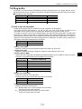
Chapter 7: Computer Link Function
7-3 Standard buffers
To access a file register using normal computer commands (command code 24(H), 34(H), etc.), a file
register address must be assigned.
Otherwise, you can use commands for a standard buffer. In this case, you have to set up a buffer in the
PC data memory, and assign it a number. Then, you call the buffer by number to select it, not its address.
The second method makes it possible to create an application without knowing the actual address in the
PC memory.
Ë Commands for standard buffers
Command code
28(H)
38(H)
68(H)
78(H)
Details
Read from a standard buffer
Write to a standard buffer
Read information about a standard buffer
Write information about a standard buffer
Reference page
7·27
7·28
7·29
7·30
[1] How to specify a standard buffer
Establish a standard buffer in data memory. The buffer size can be specified (up to 64 k-bytes), in units
of one byte. A maximum of 32 buffers can be referenced. Their buffer numbers, 00 to 1F, identifies
these buffers.
The following area in data memory can be allocated to standard buffers.
File number
file 0
file 1 to 7
File address
000000 to 017777(8)
000000 to 177777(8)
To specify a standard buffer area, specify the top file address DA, the file number DF, and the buffer
length DL. Both direct and indirect methods of creation can be used.
a) Direct specification
A method used to specify the top address, file number, and buffer length directly as JW-51CM parameters.
b) Indirect specification
Enter the top address, and file number for a standard buffer’s information storage area. Then enter
the top file address, file number, and buffer length, into that information storage area.
7·23
7
Chapter 7: Computer Link Function
Direct specification of a standard buffer
Enter the top address and buffer length of
the standard buffer as parameters
Standard buffer
Indirect assignment of a standard buffer
Enter the top address of a standard buffer’s
information storage area as the parameter.
Standard buffer
Standard buffer’s
information storage area
DA
DF
DL
7
The following data memory area can be used as a standard buffer’s information storage area.
File number
file 0
file 1 to 7
File address
000000 to 017777(8)
000000 to 177777(8)
In order to access a standard buffer, use the read and write commands (command code 28(H) and 38(H)).
To use them, assign a buffer number, an offset, and the number of bytes to access. The offset is the
displacement of the address from the top. If you assign 0 for the offset, the JW-51CM will access the top
of the buffer.
In order to access information about the buffer itself, use the read and write commands (command code
68(H) and 78(H)) to get at the standard buffer information. Using these commands, the top address, file
number, and buffer length can be read out by supplying the buffer number. The indirect assignment
method can be used to change the information they contain.
7·24
Chapter 7: Computer Link Function
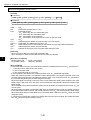
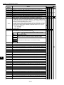
[2] Parameter setting
Use parameters 1000 to 1377 to access the standard buffer.
Parameter
address
Details
Information concerning standard buffer 00
1000 to 1007
1010 to 1017
1020 to 1027
1030 to 1037
1040 to 1047
1050 to 1057
1060 to 1067
1070 to 1077
1100 to 1107
1110 to 1117
1120 to 1127
1130 to 1137
1140 to 1147
1150 to 1157
1160 to 1167
1170 to 1177
1200 to 1207
1210 to 1217
1220 to 1227
1230 to 1237
1240 to 1247
1250 to 1257
1260 to 1267
1270 to 1277
1300 to 1307
1310 to 1317
1320 to 1327
1330 to 1337
1340 to 1347
1350 to 1357
1360 to 1367
1370 to 1377
When direct assignment (1007 =
When indirect assignment
80(H)) is used
(1007 = C0(H)) is used
1000 Top file address of the standard
Top file address of the standard
1001 buffer
buffer information storage area
1002 File number of the standard buffer File number of the standard
buffer information storage area
1003 Not used
Not used
1004 Length of the standard buffer
Not used
1005 (64 K-bytes when 0000(H))
1006 Not used
Not used
Selection of the standard buffer
00(H): Deactivate the standard buffer
1007
80(H): Direct assignment of the standard buffer
C0(H): Indirect assignment of the standard buffer
Information concerning standard buffer 01
Information concerning standard buffer 02
Information concerning standard buffer 03
Information concerning standard buffer 04
Information concerning standard buffer 05
Information concerning standard buffer 06
Information concerning standard buffer 07
Information concerning standard buffer 08
Information concerning standard buffer 09
Information concerning standard buffer 0A
Information concerning standard buffer 0B
Information concerning standard buffer 0C
Information concerning standard buffer 0D
Information concerning standard buffer 0E
Information concerning standard buffer 0F
Information concerning standard buffer 10
Information concerning standard buffer 11
Information concerning standard buffer 12
Information concerning standard buffer 13
Information concerning standard buffer 14
Information concerning standard buffer 15
Information concerning standard buffer 16
Information concerning standard buffer 17
Information concerning standard buffer 18
Information concerning standard buffer 19
Information concerning standard buffer 1A
Information concerning standard buffer 1B
Information concerning standard buffer 1C
Information concerning standard buffer 1D
Information concerning standard buffer 1E
Information concerning standard buffer 1F
7·25
7
Set the same as the information
about standard buffer 00
Chapter 7: Computer Link Function
[3] Standard buffer information storage area
When the indirect assignment method is used, set the top file address, file number, and buffer length for
the standard buffer in the standard buffer’s information storage area.
+0
+1
+2
+3
+4
+5
+6
+7
Top file address of the standard buffer (DA)
File number of the standard buffer (DF)
Not used
Standard buffer length (DL)
Entering 0000(8) creates buffer 64 k-bytes long.
Not used
[4] Error processing when accessing standard buffers
The JW-51CM performs the following operation when an error occurs when dealing with a standard
buffer.
(1) When setting parameters
If any of the parameters is not set correctly, the JW-51CM will indicate a parameter error (the ERROR lamp will light) when writing the parameters to the EEPROM.
If this happens, the JW-51CM will not write the parameters into the EEPROM and will keep the start
switch value address 3777 unchanged 81(H).
(2) When communicating
If an error occurs during communication, the JW-51CM will return a response with an error code
attached as follows:
Error code
(Hexadecimal)
7
01
48
49
4A
Details
Meaning
The standard buffer number is not correct (other than 0 to F).
The specified number of data bytes to read (write) exceeded
the maximum 1024 bytes allowed.
Undefined standard The standard buffer corresponding to the buffer number could
not be found.
buffer
The area for the corresponding buffer has not been assigned
Incorrectly identified
correctly. This was determined when the JW-51CM received
a standard buffer
a command using the indirect assignment method.
The number of bytes to read or write exceeded the buffer
Incorrect data length length of the specified buffer.
Format error
7·26
Chapter 7: Computer Link Function
[5] Description of commands used with standard buffers
Read from a standard buffer (COM = 28(H))
[Format]
Ë Command
COM
DB
Ë Response
COM RSLT
COM
DB
TAG
IPL, H
LL, H
DATA1 to N
TAG
TAG
IPH
LL
LH
DB
TAG
IPL
IPH
LL
LH
DATA1
...
DATAN
= 28(H)
= Standard buffer number (00(H) to 1F(H))
= 01(H)
= Offset address (Enter an offset value from the top of the buffer for the place to start
reading data to read)
= Data length (the number of bytes to read). Any value up to 1024 bytes.
= Read data
[Function]
· Read L bytes of data starting from offset address IP in the standard buffer DB. If 00(H) is entered for IP,
the JW-51CM will read from the top of the standard buffer.
· Up to 1024 bytes can be read at a time.
[Execution condition]
· Write enable mode
: Mode 0, mode 1, and mode 2
· PC operation status
: Stopping, operating
[Error handling]
· If the format does not match the format shown below, the module will return error 01(H) (format error).
1. The DB or TAG value is not correct.
2. The IP or L exceeds 1024.
3. The command length is not correct.
· If the ring buffer is not defined, the module will return error 48(H) (undefined standard buffer).
· While the module receives a command by indirect assignment, if the target standard buffer area is not
correctly assigned (except for the storage area shown in page 7·24), the module will return error 49(H)
(incorrectly identified standard buffer).
· If the final data address to read (the data length is L bytes from the IP address) exceeds the last
address in the standard buffer area, the module will return error 4A(H) (data length incorrect).
· If a timeout occurs while the module is accessing data using the control module, the module will return
error 0F(H) (timeout while accessing memory).
[Example]
· Read 4 bytes of data starting from address 0000(H) in standard buffer 01.
Ë Command
28
01
01
00
00
04
00
Ë Response
28
00
01
01
00
00
04
7·27
00
11
22
44
88
0000
0001
0002
0003
7
Chapter 7: Computer Link Function
Write to a standard buffer (COM = 38(H))
[Format]
Ë Command
COM
DB
TAG
IPL
IPH
LL
LH
DATA1
DB
TAG
IPL
IPH
LL
LH
...
DATAN
Ë Response
COM
COM
DB
TAG
IPL, H
LL, H
DATA1 to N
RSLT
= 38(H)
= Standard buffer number (00(H) to 1F(H))
= 01(H)
= Offset address (Enter an offset value from the top of the buffer for the place to start writing
the data)
= Data length (the number of bytes to write). Any value up to 1024 bytes.
= Write data
[Function]
· Write L byte of data starting from the offset location specified in IP, the standard buffer named in DB.
If 00(H) is entered for IP, the JW-50CM will start reading from the top of the buffer.
· Up to 1024 bytes can be read at a time.
[Execution conditions]
· Write enable mode
: Mode 0, mode 1, and mode 2
· PC operation status
: Stopping, operating
7
[Error handling]
· If the format does not match the format shown below, the module will return error 01(H) (format error).
1. The DB or TAG value is not correct.
2. The IP or L exceeds 1024.
3. The command length is not correct.
· If the standard buffer is not defined, the module will return error 48(H) (undefined standard buffer).
· While the module receives a command by indirect assignment, if the target standard buffer area is not
correctly assigned (except for the storage area shown in page 7·24), the module will return error 49(H)
(incorrectly identified standard buffer).
· If the final data address to write (the data length is L bytes from the IP address) exceeds the last
address in the standard buffer area, the module will return error 4A(H) (data length incorrect).
· If the write enable mode is set to 0, the module will return error 10(H) (mis-matched write enable mode).
· When the module detects a verification error in the written data, it will return error 07(H) (write command
verification error).
· If a timeout occurs while the module is accessing data using the control module, the module will return
error 0F(H) (timeout while accessing memory)
[Example]
· Write 12(H), 34(H), 56(H) and 78(H) to 4 bytes address starting from address 0000(H) in standard buffer 02.
Ë Command
38
02
01
00
00
04
00
12
34
12
34
56
78
Ë Response
38
00
02
01
00
00
7·28
04
00
Chapter 7: Computer Link Function
Read information about a standard buffer (COM = 68(H))
[Format]
Ë Command
COM
DB
Ë Response
COM RSLT
LBL
COM
DB
TAG
DINF
ISEG
IADRL, H
BSEG
BADRL, H
LBL, H
DB
TAG
DINF
ISEG
IADRL IADRH BSEG BADRL BADRH
LBH
= 68(H)
= Standard buffer number (00(H) to 1F(H))
= 01(H)
= Setting for the standard buffer
00(H): Not defined
01(H): Direct assignment
02(H): Indirect assignment
81(H): Indicates invalid setting for direct assignment
82(H): Indicates invalid setting for indirect assignment
If the standard buffer has not been defined, 00(H) will returned for the parameters below.
= File number of the standard buffer’s information storage area
= Top address of the standard buffer’s information storage area
When the direct assignment method is used, 0000(H) is stored in ISEG and IADR.
= File number of the standard buffer
= Top address of the standard buffer
= Buffer size (number of bytes). 0000(H) corresponds to 64 K bytes
Whether or not these settings are correct, the JW-51CM will read them. If they are incorrect, DINF will be 81(H) (direct assignment) or 82(H) (indirect assignment).
[Function]
· Read the information about the standard buffer named in DB.
[Execution conditions]
· Read enable mode
: Mode 0, mode 1, and mode 2
· PC operation status
: Stopping, operating
[Error handling]
· If the format does not match the format shown below, the module will return error 01(H) (format error).
1. The RB or TAG value is not correct.
2. The command length is not correct.
· If a timeout occurs while the module is accessing data using the control module, the module will return
error 0F(H) (timeout while accessing memory).
[Exapmle]
· Read information from standard buffer 02.
Ë Command
68
02
Ë Response
68
00
02
01
02
01
00
00
File 1, from 0000(H)
Indirect assignment
00
01
256 bytes
7·29
02
00
00
File 2, from 0000(H)
7
Chapter 7: Computer Link Function
Write information about a standard buffer (COM = 78(H))
[Format]
Ë Command
COM
DB
TAG
DINF
BSEG BADRL BADRH
LBL
LBH
Ë Response
COM
COM
DB
TAG
DINF
BSEG
BADRL, H
LBL, H
RSLT
DB
= 78(H)
= Standard buffer number (00(H) to 1F(H))
= 01(H)
= Select the assignment method for the buffer being defined
02(H): Indirect assignment
= File number of the standard buffer
= Top address of the standard buffer
= Buffer size (number of bytes). 0000(H) corresponds to 64 K-bytes
[Function]
· Write the information about the standard buffer named in DB.
· The information details consist of the buffer file number, buffer top address, and buffer size.
· The information about a direct assignment buffer cannot be changed. Changing between direct and
indirect methods of accessing a given buffer is not possible.
7
[Error handling]
· If the format does not match the format shown below, the module will return error 01(H) (format error).
1. The DB, TAG, DINF, BSEG, BADR, or LB value is not correct.
2. The command length is not correct.
· If the buffer is not defined, or the buffer assignment method is different (for example, DINF=02(H) is
assigned to the direct buffer), the module will return error 48(H) (undefined standard buffer).
· If the write enable mode is set to 0, the module will return error 10(H) (mis-matched write enable mode).
· When the module detects a verification error in the written data, it will return error 07(H) (write command
verification error).
· If a timeout occurs while the module is accessing data using the control module, the module will return
error 0F(H) (timeout while accessing memory).
[Execution conditions]
· Read enable mode
: Mode 1 and mode 2
· PC operation status
: Stopping, operating
[Example]
· Set the beginning of standard buffer 03 to address starting from 0000(H) in file 2 and make it 256 bytes
long.
Ë Command
78
03
01
02
02
00
00
File 2, from 0000(H)
Ë Response
78
00
03
7·30
00
01
256 bytes
Chapter 7: Computer Link Function
7-4 Ring buffer
A ring buffer is used to transmit data between the host computer and PC in a single direction. An assigned area inside the PC is used as a ring buffer, and data is written into and then read from this area.
Ë Commands for the ring buffer
Command code
Details
Reference page
7·40
Read from ring buffer
29(H)
Write to ring buffer
39(H)
7·42
Read the ring buffer information
69(H)
7·44
7·46
Write the ring buffer information
79(H)
[1] How to use the ring buffer
Create the ring buffer in the PC’s data memory (as a register or a file register).
The buffer size can be set to 256, 512, 1 K, 2 K, 4 K, 8 K, 16 K, 32 K, or 64 K bytes. A maximum of 16
ring buffers can be created. These ring buffers are identified by a ring buffer number (0 to F).
To create a ring buffer, enter the top address (BAH), the ring buffer file number (BF), and the buffer
length (BL). In order to access data, a write pointer (WP), and a read pointer (RP) are used. Both the
write and read pointer are kept in the ring buffer’s information storage area of data memory. Set the top
address for the ring buffer’s information storage area as a parameter. The data memory used for the
ring buffer’s information storage areas is as follows.
File number
file 0
file 1 to 7
File address
000000 to 017777(8)
000000 to 177777(8)
1) Write pointer (WP)
Address to write the next byte of data to (offset from buffer top, which is 0)
2) Read pointer (RP)
Address to read the next byte of data from (offset from the buffer top, which is 0)
3) Buffer address (BAH)
Upper bytes of the ring buffer top address (file address). Buffers can be created in units of 1 K bytes.
Therefore, the possible buffer sizes and address are as follows:
Set value
(Hexadecimal)
00
04
08
0C
:
F8
FC
Actual file address (8)
000000
002000
004000
006000
:
174000
176000
4) Buffer file number (BF)
Assign a file number to the ring buffer.
The data memory area used for the ring buffers is as follows.
File number
file 0
file 1 to 7
File address
000000 to 017777(8)
000000 to 177777(8)
5) Direction (DIR)
Assign a data transmission direction
01(H): Reading data from a control module to the JW-51CM
Use the ring buffer read command
81(H): Write data from the JW-51CM to a control module
Use the ring buffer write command
7·31
7
Chapter 7: Computer Link Function
6) Buffer length (BL)
Set the size of the ring buffer
Set value
(Hexadecimal)
00
01
02
04
08
10
20
40
80
Buffer length
64 K-bytes
256 bytes
512 bytes
1 K-bytes
2 K-bytes
4 K-bytes
8 K-bytes
16 K-bytes
32 K-bytes
To assign the top address, buffer file number, and buffer length for the ring buffer, either direct or
indirect assignment methods can be used.
a) Direct assignment
A method to assign the buffer top file address, file number, buffer length, and data transmission
direction directly in the JW-51CM parameters.
b) Indirect assignment
A method to assign the buffer top file address, file number, buffer length, and data transmission
direction in the ring buffer information storage area.
7
7·32
Chapter 7: Computer Link Function
Direct assignment of the ring buffer
Ring buffer
Store the top address for the ring buffer s information storage area and the ring buffer
top address in the JW-51CM parameters
Ring buffer information
storage area
WP
RP
Data to read
7
Ring buffer
Indirect assignment of the ring buffer
Store the top address of the ring buffer s
information storage area in the JW51CM parameters
Ring buffer information
storage area
WP
RP
BAH
BF
DIR
BL
Data to read
7·33
Chapter 7: Computer Link Function
[2] Operation of the ring buffer
Both the read pointer (RP) and write pointer (WP) start out pointing at the buffer top. To initialize these
settings, use a ladder program.
7
(1) Data transmission procedure when the read direction is from the PC to the host computer
1 Processing the data with the ladder program
If there is data to transmit, the JW-51CM will write the data starting at the current WP position. It
increases the WP by the number of bytes of data it writes into the buffer. If the WP reaches the
end of the buffer, it will be pointed back to the top (0). Be careful not to advance the WP if it will be
pointing at the same position as the RP (see page 7-48 to 7-50).
2 Processing by the JW-51CM
If the RP matches with the WP, the JW-51CM assumes that there is no data to read. If the RP
does not match with the WP data will be read from the area between the RP and the WP-1.
To read the data, use the ring buffer read command (command code 29(H)). Set the ring buffer
number and number of data bytes to read using this command. When the JW-51CM receives the
command, it will read data starting from the RP. Then, it advances the RP by the number of data
bytes to read. Pointer updating can be done ether of two ways as described below.
a) Non-confirmation type
Update the pointer at the same time the data is read. Then, the JW-51CM will send its response.
b) Confirmation type
The pointer is not updated when the data is read. The JW-51CM waits for confirmation from
the host after sending its response. When the JW-51CM receives the confirmation, it will update the pointer. Therefore, the host computer has to send a confirmation after receiving a
response.
To choose whether to use the non-confirmation or confirmation method of communication, include the method in the command. To read data continuously using the confirmation method, you
can send a data read request command for the next byte of data together with the confirmation
for the current byte of data (see page 7·36).
7·34
Chapter 7: Computer Link Function
Non-confirmation type
Host
JW-51CM
Command
ACK of the command on the TCP level commands (this is only sent
when the TCP method is used)
- Check for read data at the current pointer value
- Read the data
- Update the read pointer
Response
ACK of the command on the TCP level commands (this is only sent
when the TCP method is used)
Confirmation type
Host
JW-51CM
Command
ACK of the command on the TCP level commands (this is sent when
only the TCP method is used)
- Read data starting the current pointer location and check the data
- Read the data
Response
ACK of the response on the TCP level commands (this is sent when
only the TCP method is used)
Confirmation
ACK of the command on the TCP level commands (this is sent when
only the TCP method is used)
- Update the read pointer
7·35
7
Chapter 7: Computer Link Function
Confirmation type (when you want to attach a read command for the next byte of data to the confirmation for the
current byte of data)
Host
computer
JW-51CM
Command
ACK of the command on the TCP level commands
(this is sent when only the TCP method is used)
- Read data starting the current pointer data and check the data
- Read the data
Response
ACK of the response on the TCP level commands (this is sent when
only the TCP method is used)
Confirmation of the previous data byte and the command to read
the next byte
ACK of the confirmation on the TCP level commands (this is sent
when only the TCP method is used)
- Update the read pointer
- Check for data to read, starting from the current pointer position
- Read the data
Response
7
ACK of the response on the TCP level commands (this is sent when
only the TCP method is used)
Confirmation (when there is no request to read the next byte of data)
ACK of the above on the TCP level commands (this is sent when
only the TCP method is used)
- Update the pointer
The non-confirmation type completes the communication process in one application scan cycle.
However, if the host computer goes down when the JW-51CM returns a response after processing the command, the read pointer will be updated. But, the host computer will not receive the
response since it is down. Then, when the host computer resends this command after coming
back up, the JW-51CM will have already updated the read pointer. Therefore, the data read at the
time the host computer system goes down will actually be lost.
The confirmation type only updates the pointer after a read when the JW-51CM receives the
confirmation of its response to the host computer. Therefore, if the host computer fails to receive
the response due to the system going down, the pointer will not be updated. This decreases the
possibility that data will be lost during a crash and recovery. However, the confirmation type
needs 1.5 times the number of communication cycles, compared with the non-confirmation type.
When the number of data bytes to read is set to 0 in the command, the JW-51CM will read the
number of data bytes available. However, it can only read a maximum of 1024 bytes at one time.
7·36
Chapter 7: Computer Link Function
The JW-51CM will return the number of bytes actually read, the “continuation information” (whether
there is still data left to read in the buffer or not), and the data to be read as a response. The
relationship between the number of data bytes to read, specified in the command, and the number of data bytes actually read is shown below.
LC: Number of data bytes to read, specified in the command
LP: Number of data bytes available to read
LR: Number of data bytes actually read
Number of data bytes Number of data
to read, specified in bytes available to
the command (LC)
read (LP)
a
LP = 0
b
1
LP 1024
LC = 0
1
c
LP 1024
d
LP = 0
LP LC
2 1 LC 1024 e
LC LP
f
Continuous
information
(MORE)
Do not continue
Do not continue
Continue
Do not continue
Do not continue
Continue
Number of data
bytes actually
read (LR)
LR = 0
LR = LP
LR = 1024
LR = 0
LR = LP
LR = LC
1 When the number of data bytes to read is not specified in the command (set to 0)
a) When there is no data to read, the number of data bytes available will be 0, and the JW-51CM
will not continue trying to read.
b) When the data available to read is less than 1024 bytes, the JW-51CM will read all of the data
available and then stop reading.
c) When the amount of data to read exceeds 1024 bytes, the JW-51CM will read the first 1024
bytes of data and get ready to read another string of data.
2 When the number of data bytes to read is specified in the command
d) When there is no data to read, the number of data bytes available will be 0, and the JW-51CM
will not continue trying to read.
e) When the number of data bytes available is less than the number of data bytes specified in the
command, the JW-51CM will read out all of the data in the buffer, regardless of the number of
bytes specified, and then it will stop reading.
f) When the number of data bytes specified in the command is smaller than the number of data
bytes available to read, the JW-51CM will read the specified number of data bytes, and then
get ready to read the next string data.
(2) Data transmission procedure when the writing direction is from the host computer to the PC
1 Processing by the JW-51CM
The JW-51CM uses the ring buffer write command to write data in to the buffer (command code
39(H)). Specify a ring buffer number, the number of data bytes being written, and the data to write.
When the JW-51CM receives this command, it will writes the data starting at the current WP
position, and advances the WP by the number of data bytes it transmitted. When the WP reaches
the end of the buffer, it will be set to point back to the top (0). If the WP matches the RP (or goes
past the RP) by illegally advancing the WP, the JW-51CM will enter a buffer full error condition.
The non-confirmation and confirmation communication types are also available when writing data.
2 Processing by the ladder program
When the RP matches the WP, the JW-51CM assumes that there is no data to read. If the RP
does not match with the WP, the area from the RP to a position one less than the WP will be seen
as data to read. Temporarily move the data to read to some other type of memory (not data
memory) and then advance the RP by the number of data bytes available to read (see page 7·51
to 52).
7·37
7
Chapter 7: Computer Link Function
[3] Parameter setting
Use parameters 1400 to 1577 to create the ring buffer.
Parameter
address
Details
Information concerning ring buffer 00
1400
Top file address of the ring buffer’s information storage area
1401
1402 File number of the ring buffer’s information storage area
Enter values for 1403 to 1406 (1407 = 80(H)) when direct assignment is used.
1403
1404
1400 to 1407
1405
1406
7
1407
1410 to 1417
1420 to 1427
1430 to 1437
1440 to 1447
1450 to 1457
1460 to 1467
1470 to 1477
1500 to 1507
1510 to 1517
1520 to 1527
1530 to 1537
1540 to 1547
1550 to 1557
1560 to 1567
1570 to 1577
Ring buffer data transmission direction
Set value(H)
Details
Reads data from control module to JW-51CM
01
Writes data from JW-51CM to control module
81
Ring buffer top address (upper bytes of the file address)
Settable in units of 1 K bytes
Set value(H)
Set value(H)
File address(8)
File address(8)
00
000000
:
:
04
002000
F4
172000
08
004000
F8
174000
0C
006000
FC
176000
Ring buffer file number
Upper bytes of the ring buffer length
Buffer length
Buffer length
Set value(H)
Set value(H)
00
10
64 K bytes
4 K bytes
01
256 bytes
20
8 K bytes
512 bytes
02
16 K bytes
40
1 K bytes
04
32 K bytes
80
2 K bytes
08
Selection of the ring buffer
00(H): Disable the ring buffer
80(H): Direct assignment of the ring buffer
C0(H): Indirect assignment of the ring buffer
Information concerning ring buffer 01
Information concerning ring buffer 02
Information concerning ring buffer 03
Information concerning ring buffer 04
Information concerning ring buffer 05
Information concerning ring buffer 06
Information concerning ring buffer 07
Information concerning ring buffer 08
Information concerning ring buffer 09
Information concerning ring buffer 0A
Information concerning ring buffer 0B
Information concerning ring buffer 0C
Information concerning ring buffer 0D
Information concerning ring buffer 0E
Information concerning ring buffer 0F
7·38
Set the same as the information for ring buffer 00
Chapter 7: Computer Link Function
[4] Ring buffer information storage area (in data memory)
+0
+1
+2
+3
+4
+5
+6
+7
Write pointer (WP)
Read pointer (RP)
Upper bytes of the buffer top address (BAH)
Buffer file number (BF)
Data transmission direction (DIR)
Upper bytes of the buffer length (BL)
Only when the
indirect assignment is used
The write pointer and read pointer are used to access the ring buffer. They are incremental addresses,
using the top address of the ring buffer location 0. Upper bytes of the buffer top address (BAH), buffer
file number (BF), data transmission direction (DIR), and upper bytes of buffer length (BL) are only
assigned when indirect assignment is used. The setting details are the same as for the setting values
used as parameters when direct assignment is used.
[5] Error processing when accessing ring buffers
The JW-51CM performs the following operation when an error occurs while handling a ring buffer.
(1) When setting parameters
If any of the parameters is not set correctly, the JW-51CM will indicate a parameter error (the ERROR
lamp will light) when writing the parameters into the EEPROM.
If this happens, the JW-51CM will not write the parameters into the EERPOM and will keep the start
switch value at address 3777 unchanged 81(H).
(2) When communicating
If an error occurs during communication, the JW-51CM will return a response with an error code
attached as follows:
Error code
(Hexadecimal)
Meaning
Details
01
Format error
40
Undefined ring buffer
41
Incorrectly identified
a ring buffer
42
Incorrect pointer
43
No free area
44
Buffer overflow
The specified buffer number was not correct (other than 0 to
F). The specified data length to read (write) exceeded the
maximum 1024 bytes allowed.
The ring buffer corresponding to the buffer number could not
be found.
The area for the corresponding buffer has not been assigned
correctly. This was determined when the JW-51CM received a
command using the indirect assignment method.
The current read and/or writes pointer values are outside of
the buffer range. This was determined when the JW-51CM received a command.
The data you want to write will exceed the free space in the
buffer when the data is actually written. (When the write pointer
is advanced the actual number of bytes to be written, it will
equal or exceed the read pointer position.)
The data you want to write is larger than the buffer can hold.
7·39
7
Chapter 7: Computer Link Function
[6] Description of commands used with ring buffers
Read a ring buffer (COM = 29(H))
[Format]
Ë Command
COM
RB
FUN
TAG
LCL
LCH
TAG
RPL
RPH
Ë Response
COM
RSLT
RB
DATA1
...
DATAN
LRL
LRH
MORE
COM
RB
FUN
7
= 29(H)
= Ring buffer number (00(H) to 1F(H))
= Selected function
01(H): Reading using the non-confirmation type
81(H): Reading using the confirmation type
82(H): Confirmation of the response
83(H): Confirmation of the response and value of next byte read
TAG
= 01(H)
LCL, H
= Data length (the number of bytes to read)
0000(H) to 0400(H). If 0000(H) is entered, the JW-51CM will read the number of data bytes
currently stored in the buffer.
(Max. 1024 bytes)
RPL, H
= Read pointer for the data to read (offset from the buffer top address)
LRL, H
= Data length (the number of bytes to read).
MORE = Continuation information
00(H): There is no more data to read.
01(H): There is data not yet read.
DATA1 to N = Read data. The data length is given in LR.
[Function]
· Read LC bytes of data starting from the ring buffer specified by RB. If 00(H) is entered for LC, the JW51CM will read all of the unread data in the ring buffer up to 1024 bytes.
· The response will contain data length, LR, which expresses number of bytes actually read, and the
continuation information MORE, which tells whether or not there is more data to read after executing
the command.
· After executing this command, the read pointer in the ring buffer is advanced by LR. The timing for
advancing the pointer depends on whether the non-confirmation and confirmation type was used.
· Non-confirmation type
: Pointer advanced after reading the data (before returning the response)
· Confirmation type
: Pointer advanced after receiving the confirmation of the response from
the host computer.
7·40
Chapter 7: Computer Link Function
· The number of data bytes actually read will vary considerably, based the number of data bytes left to
read in the ring buffer and the number of bytes requested in the read command. The relationship of
these factors is shown below.
LC: Number of data bytes to read, specified in the command
LP: Number of data bytes available to read
LR: Number of data bytes actually read
Number of data bytes Number of data Continuation Number of data
information
bytes available
to read, specified in
bytes actually
(MORE)
to read (LP)
the command (LC)
read (LR)
00(H)
LP = 0
LR = 0
00(H)
1 LP 1024
LR = LP
LC = 0
01(H)
LP 1024
LR = 1024
00(H)
LP = 0
LR = 0
00(H)
LP LC
LR = LP
1 LC 1024
01(H)
LC LP
LR = LC
[Execution conditions]
· Write enable mode
: Mode 0, mode 1, and mode 2
· PC operation status
: Stopping, operating
[Error handling]
· If the format does not match the format shown below, the module will return error 01(H) (format error).
1. The RB, FUN, or TAG value is not correct.
2. The LC exceeds 1024.
3. The command length is not correct.
· If the ring buffer is not defined, the module will return error 40(H) (undefined ring buffer).
· When the module receives a command by indirect assignment, if the target ring buffer area is not
correctly defined (except for the storage area shown in page 7·32), it will return error 41(H) (the area for
the corresponding ring buffer has not been assigned correctly).
· When the module is receiving a command, if the current read and/or write pointer values are out of the
buffer range, it will return error 42(H) (the current read and/or write pointer values are outside of the
buffer range).
· If a timeout occurs while the module is accessing data using the control module, the module will return
error 0F(H) (timeout while accessing memory).
[Example]
· Read 4 bytes of data in ring buffer 01 using the confirmation type.
Ë Command
29
01
81
01
04
00
01
01
03
00
Ë Response
29
00
RP
12
34
56
78
0003
0004
0005
0006
04
00
Data length
7·41
00
7
Chapter 7: Computer Link Function
Write to a ring buffer (COM = 39(H))
[Format]
Ë Command
COM
RB
FUN
TAG
LCL
LCH
DATA1
...
DATAN
RB
TAG
WPL
WPH
LRL
LRH
LEL
Ë Response
COM
COM
RB
FUN
TAG
LCL, H
DATA1 to N
WPL, H
LRR, H
LEL, H
RSLT
LEH
= 39(H)
= Ring buffer number (00(H) to 1F(H))
= Selected function
01(H): Write using the non-confirmation type
81(H): Write using the confirmation type
82(H): Confirmation of the response
83(H): Confirmation of the response and value of next byte write
= 01(H)
= Data length (the number of bytes to write). Up to 1024 bytes.
= Write data. The data length is given in LC.
= Write pointer for the next location to write (offset from the ring buffer top address)
= Data length (the number of bytes to write).
= Number of free bytes in the ring buffer after writing the data
[Function]
· Write LC bytes of data in the ring buffer specified in RB.
· Up to 1024 bytes of data can be written at one time using this function.
7
[Execution conditions]
· Write enable mode
: Mode 1 and mode 2
· PC operation status
: Stopping, operating
[Error handling]
· If the format does not match the format shown below, the module will return error 01(H) (format error).
1. The RB, FUN, or TAG value is not correct.
2. The LC exceeds 1024.
3. The command length is not correct.
· If the ring buffer is not defined, the module will return error 40(H) (undefined ring buffer).
· When the module receives a command by indirect assignment, if the target ring buffer area is not
correctly defined (except for the storage area shown in page 7·32), it will return error 41(H) (the area for
the corresponding buffer has not been assigned correctly).
· When the module is receiving a command, if the current read and/or write pointer values are out of the
buffer range, it will return error 42(H) (the current read and/or write pointer values are outside of the
buffer range).
· When the data to be written exceeds the vacant area in the buffer, the module will return error 43(H) (no
area to write).
· When the data to be written exceeds the buffer area, the module will return error 44(H) (buffer overflow).
· If the write enable mode is set to 0, the module will return error 10(H) (mis-matched write enable mode).
· When the module detects a verification error in the written data, it will return error 07(H) (write command
verification error).
· If a timeout occurs while the module is accessing data using the control module, the module will return
error 0F(H) (timeout while accessing memory).
7·42
Chapter 7: Computer Link Function
[Example]
· Write 4 bytes of data 01(H), 02(H), 03(H), and 04(H) in ring buffer 01 using the confirmation type.
Ë Command
39
01
81
01
04
00
01
02
03
04
01
01
10
00
04
00
20
00
Ë Response
39
00
WP
Data length
Free area:
32 bytes
7
7·43
Chapter 7: Computer Link Function
Read information about a ring buffer (COM = 69(H))
[Format]
Ë Command
COM
RB
Ë Response
COM RSLT
WPL
WPH
RB
TAG
DINF
ISEG
RPL
RPH
DIR
LBL
IADRL IADRH BSEG BADRL BADRH
LBH
COM
RB
TAG
DINF
7
= 69(H)
= Ring buffer number (00(H) to 0F(H))
= 01(H)
= Setting for the ring buffer
00(H): Not defined
81(H): Indicates invalid setting for direct assignment
01(H): Direct assignment
82(H): Indicates invalid setting for indirect assignment
02(H): Indirect assignment
If the ring buffer has not been defined, 00(H) will be returned for the parameters below.
ISEG
= File number of the ring buffer’s information storage area
IADRL, H = Top address of the ring buffer’s information storage area
BSEG = File number of the ring buffer
BADRL, H = Top address of the ring buffer
WPL, H
= Write pointer (offset from the top of the buffer)
RPL, H
= Read pointer (offset from the top of the buffer)
DIR
= Data transmission direction
80(H): Data flow direction (from control module to JW-51CM)
81(H): Data flow direction (from JW-51CM to control module)
LBL, H
= Buffer size (number of bytes). 0000(H) corresponds to 64 K-bytes.
Regardless of whether or not these settings are correct, the JW-51CM will read them. If they are incorrect, DINF will be 81(H) (direct assignment) or 82(H) (indirect assignment).
[Function]
· Read the information about the ring buffer named in RB.
[Execution conditions]
· Read enable mode
: Mode 0, mode 1, and mode 2
· PC operation status
: Stopping, operating
[Error handling]
· If the format does not match the format shown below, the module will return error 01(H) (format error).
1. The RB value is not correct.
2. The command length is not correct.
· If a timeout occurs while the module is accessing data using the control module, the module will return
error 0F(H) (timeout while accessing memory).
7·44
Chapter 7: Computer Link Function
[Example]
· Read information from ring buffer 01.
Ë Command
69
01
Ë Response
69
00
01
01
01
00
00
Register 09000
Direct assignment
03
00
WP
06
00
RP
81
00
08
00
00
0C
Register 29000
04
1 K bytes
Writing data
7
7·45
Chapter 7: Computer Link Function
Write information about a ring buffer (COM = 79(H))
[Format]
Ë Command
COM
RB
TAG
DIR
LBL
LBH
DINF
BSEG BADRL BADRH
WPL
WPH
RPL
RPH
Ë Response
COM
COM
RB
TAG
DINF
BSEG
BADRL, H
RPL, H
WPL, H
DIR
LBL, H
7
RSLT
RB
= 79(H)
= Ring buffer number (00(H) to 0F(H))
= 01(H)
= Select the assignment method for the buffer being defined
01(H): Direct assignment (When direct assignment is selected, the contents of BSEG and
BADR will be ignored)
02(H): Indirect assignment
= File number of the ring buffer
= Top address of the ring buffer
= Read pointer (offset from the top of the buffer)
= Write pointer (offset from the top of the buffer)
= Data transmission direction
80(H): Data flow direction (from control module to JW-51CM)
81(H): Data flow direction (from JW-51CM to control module)
= Buffer size (number of bytes). 0000(H) corresponds to 64 K-bytes.
[Function]
· Write the information about the ring buffer that is named in RB.
· The information details consist of the buffer file number, buffer top address, read pointer, write pointer,
data transmission direction, and buffer size.
· When direct assignment is used for the ring buffer, this write command (79(H)) cannot be used to change
the buffer file number, buffer top address, data transmission direction, or buffer size, since they are set
using parameters. (The values corresponding to these items in the command will be ignored.) Selection
between direct and indirect assignment is also set using a parameter, and cannot be changed by this
command.
[Execution conditions]
· Read enable mode
: Mode 1 and mode 2
· PC operation status
: Stopping, operating
[Error handling]
· If the format does not match the format shown below, the module will return error 01(H) (format error).
1. The RB, TAG, DINF, BSEG, BADR, WP, RP, DIR, or LB value is not correct.
2. The command length is not correct.
· If the buffer is not defined, or the buffer assignment method is different (for example, DINF=02(H) is
assigned to the direct buffer), the module will return error 48(H) (undefined standard buffer).
· If the write enable mode is set to 0, the module will return error 10(H) (mis-matched write enable mode).
· When the module detects a verification error in the written data, it returns error 07(H) (write command
verification error).
· If a timeout occurs while the module is accessing data using the control module, the module will return
error 0F(H) (timeout while accessing memory).
7·46
Chapter 7: Computer Link Function
[Example]
· Set ring buffer 04 in file 3 to 0000(H) and make it 32 K-bytes long. Set the write pointer to 0003(H) and the
read pointer to 0010(H).
Ë Command
79
04
01
80
00
80
02
03
00
00
File 3, from 0000(H)
Indirect assignment
03
00
WP
10
00
RP
32 K- bytes
Reading
Ë Response
79
00
04
7
7·47
Chapter 7: Computer Link Function
[7] An example using the ring buffer
(1) Data flow direction (from PC to the host computer)
· Direct assignment
· Ring buffer 01
Size and address: Occupy 1 K-bytes starting at 29000
· Ring buffer information storage area: Starts at 09000
Ë Parameter settings
Parameter address Set value
1410, 1411
004000(8)
00
1412
01(H)
1413
0C(H)
1414
00
1415
04
1416
80(H)
1417
Details
File 004000
09000
File 0
Data flow direction
File 006000
29000
File 0
1 K-bytes
Direct assignment
Ë Processing ladder program
1 Initialize the pointers
The read and write pointers should be initialized (set to 0) using a ladder program when starting the JW-51CM.
2 Write data to a ring buffer
If there is free space in the ring buffer, write data in it.
In this example, we assume that the data is written starting at 49000, and set the number of
bytes to write in locations 09100 and 09101.
3 Update the WP
After transmitting the data, the JW-51CM updates the WP.
7
There are two ways to transmit data, as shown below:
Data
Ring buffer
49000
Data
29000
49000
Ring buffer
29000
+ WP after update
+ RP
+ WP before
update
+ RP
+ WP after
update
59777
39777
(a) Normal case
59777
+ WP before update
39777
(b) Write to the end of the buffer and
return to the top
7·48
Chapter 7: Computer Link Function
09000, 1
09002, 3
09010, 11
09012, 13
09014, 15
09030 to 32
09040 to 42
WP
RP
Work register for number of data bytes transmitted
Constant (1024)
For checking the buffer size
Data buffer pointer
Ring buffer pointer
Initial setting
Initialize
F-44
Request
F-07W
1024 09012
DCML
· Set the constant (1 K-bytes).
F-71
CONS
0
09000 09003
· Initialize RP and WP.
F-08
OCT
0
09032
· Initialize the file number for the data buffer
pointer.
F-08
OCT
0
09042
· Initialize the file number for the ring buffer
pointer.
F-32
00610
SET
00610 turns ON to make a request to send.
F-47
ONLS
00610
Calculate the free area in the buffer.
F-211W
09002 09000 09014
SUB
· RP–WP
F-64W
09014
DEC
· Subtract one, in order to keep the RP ahead
of the WP.
FC13W
001777 09014
AND
· Mask 1 K-byte area.
F-12W
09014 09100
CMP
00610
07356
Compare the number of bytes of data to be
transmitted with the free space in the buffer.
00620 Turn ON when there is enough free space in the
buffer.
00620
F-210W
09000 09100 09014
ADD
Check the instruction type for whether to return
to the top or not when RP reaches the end of
the buffer.
FC12W
09014 002001
CMP
00620
07354
00600
00620
07354
00601
(a) The normal case
(b) Write to the end of the buffer and return to
the top.
Data transmission for case (a)
00600
F-210W
006000 09040
ADD 09000
F-76
09100 49000 @09040
FILR
7·49
· Calculate the ring buffer pointer (absolute
address) using the WP.
· Data transmission
7
Chapter 7: Computer Link Function
00601
F-211W
09012 09000 09010
SUB
Data transmission for case (b)
- Calculate the number of bytes from the current WP to the end of the ring buffer.
FC210W
09000 006000 09040
ADD
- Calculate ring buffer pointer (absolute address) using the WP.
F-76
09010 49000 @09040
FILR
- Data transmission
FC210W
09010 010000 09030
ADD
- Enter the data buffer pointer of the last half
(file 0, 010000 = 49000).
F-211W
09100 09010 09010
SUB
- Calculate the number of bytes remaining.
F-76
09010 @09030 29000
FILR
00600
F-210W
09000 09100 09000
ADD
00601
Update the WP
FC13W
1777 09000
AND
F-33
00610
RST
End of data transmission
F-48
ONLR
00610
7
- Transfer the balance of the data
TMR
0600
000
T000
00100
If the data transmission terminates less than
one minute after the request to send, the
JW-51CM will indicates that an error has occurred.
This will also happen when there is no free
space in the ring buffer and the host computer does not pick up the data with the ring
buffer read command.
Reset
00100
It is recommended that the host computer be instructed to periodically issue a ring buffer read command and pick up any data
waiting in the buffer.
7·50
Chapter 7: Computer Link Function
(2) Data flow direction (from host computer to the PC)
· Direct assignment
· Ring buffer 01
Size and address: Occupy 1 K bytes starting at 29000
· Ring buffer information storage area: Starts at 09000
Ë Parameter settings
Parameter address
1410, 1411
1412
1413
1414
1415
1416
1417
Set value
004000(8)
00
81(H)
0C(H)
00
04
80(H)
Details
File 004000
09000
File 0
Data flow direction
File 006000
29000
File 0
1 K-bytes
Direct assignment
Ë Processing ladder program
1 Initialize the pointers
The read and write pointers should be initialized (set to 0) using a ladder program when starting the JW-51CM.
2 Picking up the write data
When the JW-51CM receives a ring buffer write command from the host computer, it will pick
up the data that has been received (temporarily stored in other memory). To find out whether it
has been received or not, check whether the WP and RP are in the same position. To determine the number of bytes received, compare WP and RP values.
3 Update the RP
After temporarily storing the data, the JW-51CM updates the RP.
7
There are two ways to transmit data, as shown below:
Buffer used to
store the data
temporarily
49000
Ring buffer
29000
Ring buffer
29000
Buffer used to
store the data
temporarily
49000
+ WP
+ RP
+ WP
+ RP
39777
59777
(a) Normal case
39777
59777
(b) Write to the end of the buffer and
return to the top
7·51
Chapter 7: Computer Link Function
09000, 1
09002, 3
09010, 11
09012, 13
09030 to 32
09040 to 42
WP
RP
Number of data bytes transmitted
Constant (1024)
Temporary storage buffer pointer
Ring buffer pointer
Initial setting
Initialize
· Set the constant (1 K-bytes).
F-71
CONS
0
09000 09003
· Initialize RP and WP.
F-08
OCT
0
09032
· Initialize the file number of the temporary data
storage buffer pointer.
F-08
OCT
0
09042
· Initialize the file number of the ring buffer
pointer.
Check for fresh data
07366
07357
F-07W
1024 09012
DCML
F-12W
09000 09002
CMP
07354
· Whether the WP has been updated.
00600
07356
00601
(a) Normal update method (WP > RP).
(b) Write to the buffer end and return to the top
(WP < RP).
Method (a)
7
00600
00601
00600
F-211W
09000 09002 09010
SUB
· Calculate the number of data bytes written.
FC210W
09002 006000 09040
ADD
· Calculate the top data address from the RP.
F-76
09010 @09040 49000
FILR
· Transmit the data to the temporary storage
buffer.
F-211W
09012 09002 09010
SUB
Method (b)
· Calculate the number of data bytes written.
(From RP to the end of the ring buffer)
FC210W
09002 006000 09040
ADD
· Calculate the data top address from the RP.
F-76
09010 @09040 49000
FILR
· Transmit the data to the temporarily storage
buffer.
FC210W
09010 010000 09030
ADD
· Update the temporary storage buffer pointer.
(File 0, 010000 = 49000)
F-76
09000 29000 @09030
FILR
· Transfer the balance of the data (from top of
the ring buffer to the WP) to the temporary
storage buffer.
F-00W
09000 09002
XFER
Update the RP.
00601
7·52
Chapter 7: Computer Link Function
7-5 Computer link error code table
RSLT
(Hexadecimal)
Details
00
Normally end
01
Format error
06
PC does not stop operation
07
Verify error of write command.
0F
Time out while accessing memory.
13
Tried to set/reset TMR/CNT while PC stops operation.
10
Miss match write enable mode.
40
Undefined ring buffer
41
The area for the corresponding buffer has not been assigned correctly.
42
The current read and/or writes pointer values are outside of the buffer
range.
43
The data you want to write will exceed the free space in the buffer when
the data is actually written.
44
The data you want to write is larger than the buffer can hold.
48
Undefined standard buffer
49
Incorrectly identified a standard buffer
4A
The number of bytes to read or write exceeded the buffer length of the
standard buffer.
7·53
7
Chapter 7: Computer Link Function
7-6 Command execution completion information
When the JW-51CM completes execution of a computer link command, it writes the completion details in
the PC’s data memory.
This function can be selected by setting a parameter.
[1] Setting the parameters
Parameter
address
Details
Set the command execution completion information storage area
3660
to
3667
3660
3661
3662
3663
3664
3665
3666
3667
Top file address of the command execution completion information
File number of the command execution completion information
Not used
Set the number of command execution completion information bytes
Assign at least 16 bytes. 64 bytes is the maximum size.
Not used
This information will become effective when 80(H) is entered
[2] Command execution completion information
The command execution completion information has the following format.
7
+00
+01
+02
+03
+04
+05
+06
+07
+10
+12
+13
+14
+15
+16
:
+n
Target station IP address
Target station port number
Connection number of the source station
00(H)
Execution result
Copy to the receive command (except the header)
This area is written after the JW-51CM executes the command. To clear the contents, use the ladder
program.
The following area in the data memory can be used for this format.
File number
file 0
file 1 to 7
File address
000000 to 017777(8)
000000 to 177777(8)
7·54
Chapter 7: Computer Link Function
7-7 Time interval required for communication
The time interval after the JW-51CM receives the command until its sends the response varies with the
PC scan time, the number of nodes connected, communication data volume, etc. Shown below is a
rough estimate of the time interval.
Assumption: Number of nodes connected: 1. PC scan time: 8 ms. Data: 1024 bytes
(1) When the TCP method is used
JW-51CM
Host computer
Command
a
ACK for the command
b
Response
ACK for the response
a: Time after receiving the command until returning the TCP level ACK for the command.
10 ms on average
b: Time after returning an ACK until a response is sent
40 ms on average
This time includes the time that the JW-51CM must wait to access the control
module. (Maximum PC scan time.)
(2) When the UDP method is used
Host computer
JW-51CM
Command
a
Response
a: Time after receiving the command until a response is sent
40 ms on average
This time includes the time that the JW-51CM must wait to access the control
module. (Maximum PC scan time.)
Note: The time intervals above are for reference only. They may vary with each change in conditions.
Generally, the communication time will be longer in the conditions below:
1) When the number of ports used is increased.
2) When the PC scan time gets longer.
7·55
7
Chapter 7: Computer Link Function
7-8 Two-layer communication with satellite net
In order to communicate with the satellite net on a different layer, use the following information in the
communication format header (see page 7·1) as an extension header.
0
1
2
3
4
5
6
7
8
9
00(H)
00(H)
00(H)
00(H)
PDA
PSA
FT0
PO0
EA1
FT1
Host computer
PSA
Ethernet
PC
40 bytes
PDA
(JW-51CM)
PO0
(JW-20CM)
00(H)
PC
39
40
Satellite net
EA1
(JW-20CM)
Command line
7
· When making a two-layer communication with a satellite net, the frame needs to contain the information
including the source, transit stations, and destination, and slot number (i.e. designating the communication path). The satellite net uses eight bits to represent a station number. For that reason, when designating a module on the Ethernet, a station number for the satellite net needs to be designated. The
address is referred to as a pseudo station number.
(a) PDA
: Pseudo destination address
Designate the station number of JW-51CM that connects with the satellite net. This
may be any value within the range from 01(H) to 40(H) that can be descriminated from
other equipment on the Ethernet.
(b) PSA
: Pseudo source address
Designate the station number for the equipment sending the command. This may be
any value within the range from 01(H) to 40(H) that can be discriminated from other
equipment on the Ethernet.
With respect to the response, the pseudo target station number that is given by the
command will be set.
(c) FT0
: Frame type 0
Designate 60(H).
(d) PO0
: Transit slot number
Assign a slot number where the JW-20CM satellite network module is installed on
the junction station PC. The slots are numbered 2, 3, 4 and so on up to 7, starting
from the slot after the control module (when the ZW-6CC basic rack panel is used).
e) EA1
: End target station address
Designate the end target station address 01(H) to 40(H) on the satellite net. If the data
link master station is the destination, set the 40(H).
(f) FT1
: Frame type 1
Set the 40(H).
(g) Command line : Command/response line
c-ID/r-ID and after of communication format (page 7·1)
7·56
Chapter 7: Computer Link Function
Note
The two-layer communication is possible only with the computer link to the module on the satellite net
from the host computer on the Ethernet via transit stations. Communication in the reverse direction, or
the computer link from the host computer on the satellite net to this module, is not possible.
Example: In the following example as shown in the diagram, the expansion header needs to be as
follows.
0
1
2
3
4
5
6
7
8
9
00(H)
00(H)
00(H)
00(H)
PDA = 05(H)
PSA = 03(H)
FT0 = 60(H)
PO0 = 03(H)
EA1 = 10(H)
FT1 = 40(H)
192.9.200.3
PSA 03
Ethernet
40 bytes
192.9.200.5
PDA
05
PO0
Slot 3
00(H)
39
40
Satellite net
7
Command line
EA1
20(8)
7·57
Chapter 8: Send/Receive Functions
Chapter 8: Send/Receive Functions
The send/receive functions transmit data from this module to other stations or receive data from other stations.
The send/receive functions have two types : instruction system and data memory starting system.
8-1 Instruction system
[1] Source/destination address and channel
The send/receive instructions set the rack, slot, and channel addresses of the mounted module, target
station number, and the data memory addresses on the target station of the implemented module by the
F-202(OPCH) instruction, and the data memory address on the JW-51CM and the number of bytes to
be transmitted by the F-204 (send) or F-205 (receive) instructions.
Among the above items, the channel number and the target station number are expressed in the address system of the satellite net. The JW-51CM corresponds these with the following.
(1) Channel number
Channel numbers CH0 to CH3 correspond to the following port address.
No. of channels
CH0
Port address
6000(H)
CH1
6001(H)
CH2
6002(H)
CH3
6003(H)
Those stations, using the send/receive instructions, need to open the connection using the above
port numbers. Use TCP_Active or UDP for the connection used for the send/receive instructions.
The method for opening the target station is as shown below.
Instruction starting station Communication target station
TCP_Active
TCP_Passive
UDP
UDP
Any value may be used for the port number of the target station.
(2) Target station number
The correspondence of the target station number includes two types: automatic correspondence
and individual registration.
a) Automatic correspondence
This method assumes the station number of the send/receive instructions as the node number of
the target station IP address, and fixes the connected port to 6010(H). When the target station
number is set to 000, the node number of the IP address becomes 40(H).
b) Individual registration
This method registers the parameters of the correspondence of the station number designated by
F-202 to the IP address port number of the actual target station. Up to 31 records of correspondence may be set.
The choice between the automatic correspondence and the individual registration is set by a
parameter.
8·1
8
Chapter 8: Send/Receive Functions
» Parameters for “automatic/individual” registration
Parameter
address
Details
Assign a station number corresponding to the table (for SEND/RECEIVE)
Assignment of the relationship between the station number used with the
send/receive function and the actual address.
If automatic is selected, the JW-51CM treats the target station numbers as
node numbers on the IP addresses, and sets the target port to 6010(H).
If individual is selected, a maximum of 31 types of relationship can be regis0400
tered concerning the relationship between the station number used with the
command and the target address. (Parameters 0410 to 0777 can be used with
this selection.)
01(H): Automatic
02(H): Individual
0401 to 0407 Reserved area
Station number correspondence table 1.
This is effective only when parameter 0400 is 02(H).
Setting 00(H): Not set (the information below will be ignored)
0410
01(H): Set
0411 Target station number
0410
0412 Target station port number
to
0413 (assign a part as one word of data (two bytes) in octal notation)
0417
0414
0415
Target station IP address (0417 is host ID)
0416
0417
Station number corresponding table 2.
0420 to 0427 This is effective only when parameter 0400 is 02(H).
Station number corresponding table 3.
0430 to 0437 This is effective only when parameter 0400 is 02(H).
8
Station number corresponding table 36.
This is effective only when parameter 0400 is 02(H).
Station number corresponding table 37.
0770 to 0777
This is effective only when parameter 0400 is 02(H).
0760 to 0767
Set the same as
the station numbers
in correspondence
table 1.
(3) TCP connection and disconnection
The send/receive instructions have nothing to do with the concept of establishing/breaking the connection. When establishing or breaking the connection is required when using the send/receive functions at the port that has been opened in TCP_Active, this operation corresponds to the subsequent
send/receive instructions.
a) Establishing the connection
Executing the send/receive functions with the memory
F-202 PORTaddress of the target station file number = 0, file adOPCH CH-ST file0 177777
dress = 177777(8), and the number of bytes transmitF-204
ted = 0 will start the connection establishing operaSEND 000 ]0000
tions with the target station.
Enter any register
The connection takes approximately two seconds to
as it will be ignored.
complete.
F-205 (RCV) is also available.
b) Disconnection
Executing the send/receive functions with the memory
address of the target station file number =0, file adF-202 PORTdress = 177776(8), and the number of bytes transmitOPCH CH-ST file0 177776
ted = 0 will start the disconnecting operations from
F-204
the target station.
SEND 000 ]0000
c) Data transmission
Enter any register
Any address and number of bytes transmitted other
as it will be ignored.
than shown at a) and b) will start the actual send/
F-205 (RCV) is also available.
receive operations.
No connection and/or disconnection is required when the opening is made in UDP.
8·2
Chapter 8: Send/Receive Functions
[2] SEND/RECEIVE instructions operation
(1) Send
This function operates by the combination of F-202 (OPCH) and F-204 (SEND).
F-202 PORTfileN
OPCH CH-ST
F-204
SEND
PORT
CH
ST
file N
ADRS
n
S
n
D
S
: The port (slot) where the JW-51CM is installed.
: Channel number used (0 to 3)
Channels CH0 to CH3 correspond to 6000(H) to 6003(H).
: Target station number (00 to 77(8))
Actual target IP address and port number are determined by the station number correspondence table. (See page 8·2)
: Data area of the target station PC (file number)
: Data area top file address of target station PC
: Number of data bytes transmitted (000 to 377(8), 256 bytes at 000)
: Data area top register of source station data
Target station ST
(Actual IP and port are determined
by the station number correspondence table.)
fileN
Port number
corresponding to CH
D →
Source station
file0
S →
Sending
n
Response
8
Flag
Flag status during and after the operation
Zero Carry Error Non-carry
07357 07356 07356 07356
No response from port
0
0
1
Explanation
0
The JW-51CM is not installed in the slot.
Communication jam
0
0
0
1
This condition may instantaneously occur while other
send instruction is being executed.
However, as soon as the condition becomes clear
for the execution of an instruction, the status will turn
to Communicating.
Communicating
1
0
0
1
The communicating is being run. Once the communication completes, the status will change to either
normal end or abnormal end.
Normal end
0
1
0
0
When the send instruction has successfully
completed.
Abnormal end (time out)
0
1
1
0
Abnormal end (error)
1
1
1
0
When there is no response from the other end.
Some of the potential causes :
No connection existent.
A communication attempt has been made without
establishing any connection in TCP.
A connection-establishing attempt has been made
when a connection is already established in TCP.
8·3
Chapter 8: Send/Receive Functions
Ë Sample of program
When transferring 8 bytes of data from source station register ]1000 to the register 09000 of the
target station number 03 :
Port number installed on JW-51CM of source station : 2
Channel used
:0
00000
F-44
↑
F-32
14000
SET
Switch
14000
F-202
2-0-03
OPCH
F-204
010
SEND
14000 07354
07355 07356
Non-carry Error
T000
Set the sending relay 14000.
F-44
↑
Carry
0
004000
]1000
07357
Zero
F-33
14000
RST
TMR
000
Port 2, CH0, station number 3,
File number 0
File address 004000
Transfers 8 bytes of the range
]1000 to 1007.
0010
Detects non-execution at power ON.
(Flags do not change for one second.)
Resets 14000 when the execution
completes.
07355
Error
07356
Carry
8
In this sample program, the send function is executed to transfer data to the target station corresponding to 3 on the station number correspondence table. The number of the ports used on
source station is 6000(H).
Note
• The entry condition of F-202 or 204 instruction needs to be kept ON until the execution of the
instruction completes (or until any error occurs or the carry flags turns ON). If the entry condition
turns OFF while the instruction is being run, the instruction will end in an incomplete condition.
Once this condition occurs, a “communication jam” occurs when an instruction execution is attempted the next time, and the instruction will not run properly. To restore the condition, power
OFF the PC, and turn it ON again.
• If the entry condition turns OFF, due to an instantaneous power failure, turn the entry condition to
“latched relay” as a remedy. If, however, any power loss occurs while an instruction is being run
using “latched relay,” turning the power ON again will cause F-202 or F-204 instructions process
being run to disappear, and the entry condition will stay ON. Therefore, the start of the entry may
not be detected. Since, in this case, all flags will be turned OFF, detect the continuation of the OFF
condition of all flags using the timer, and then reset the entry condition before running the next
instruction.
8·4
Chapter 8: Send/Receive Functions
(2) Receive
This function is executed by the combination of F-202 (OPCH) and F-205 (RCV).
F-202 PORTfileN ADRS
OPCH CH-ST
F-205
RCV
PORT
CH
ST
file N
ADRS
n
D
n
D
: Port (or slot) where the JW-51CM is installed
: Channel number used (0 to 3)
Channels CH0 to CH3 correspond to 6000(H) to 6003(H).
: Target station number (00 to 77(8))
Actual target IP address and port number are determined by the station number correspondence table. (See page 8·2)
: Data area of the target station PC (file number)
: Data area top file address of target station PC
: Number of data bytes transmitted (000 to 377(8), 256 bytes at 000)
: Data area top register of source station data
Target station ST
(Actual IP and port are determined
by the station number correspondence table.)
fileN
Port number
corresponding to CH.
S →
Sending
Source station
file0
D →
n
Response
8
Flag
Flag status during and after the operation
Zero Carry Error Non-carry
07357 07356 07356 07356
No response from port
0
0
1
Explanation
0
The JW-51CM is not installed in the slot.
Communication jam
0
0
0
1
This condition may instantaneously occur while other
receive instruction is being executed.
However, as soon as the condition becomes clear
for the execution of an instruction, the status will turn
to Communicating.
Communicating
1
0
0
1
The communicating is being run. Once the communication completes, the status will change to either
normal end or abnormal end.
Normal end
0
1
0
0
When the receive instruction has successfully
completed.
Abnormal end (time out)
0
1
1
0
Abnormal end (error)
1
1
1
0
When no response from the other end.
Some of the potential causes :
No connection existent.
A communication attempt has been made without
establishing any connection in TCP.
A connection-establishing attempt has been made
when a connection is already established in TCP.
8·5
Chapter 8: Send/Receive Functions
Ë Sample of program
When transferring 8 bytes of data from the register ]1000 of target station 03 to the register 09000
of the source station.
Port number installed on JW-51CM of source station : 2
Channel used
:0
00000
F-44
↑
F-32
14000
SET
Switch
14000
F-202
2-0-03
OPCH
F-205
RCV
14000 07354
07355 07356
Non-carry Error
T000
F-44
↑
Carry
0
001000
010 09000
07357
Zero
F-33
14000
RST
TMR
000
Port 2, CH0, Station number 3,
File number 0
FIle address 001000
Transfers 8 bytes of the range
09000 to 09007
0010
Detects non-execution at power ON.
(Flags do not change for one second.)
Resets 14000 when the execution
completes.
07355
Error
07356
Carry
8
In this sample program, the receive function is executed to transfer data to the target station
corresponding to 3 on the station number correspondence table. The number of the ports used on
source station is 6000(H).
Note
• The entry condition of F-202 or 205 instruction needs to be kept ON until the execution of the
instruction completes (or until any error occurs or the carry flags turns ON). If the entry condition
turns OFF while the instruction is being run, the instruction will end in an incomplete condition.
Once this condition occurs, a “communication jam” occurs when an instruction execution is attempted the next time, and the instruction will not run properly. To restore the condition, power
OFF the PC, and turn it ON again.
• If the entry condition turns OFF, due to an instantaneous power failure, turn the entry condition to
“latched relay” as a remedy. If, however, any power loss occurs while an instruction is being run
using “latched relay,” turning the power ON again will cause F-202 or F-205 instructions process
being run to disappear, and the entry condition will stay ON. Therefore, the start of the entry may
not be detected. Since, in this case, all flags will be turned OFF, detect the continuation of the OFF
condition of all flags using the timer, and then reset the entry condition before running the next
instruction.
8·6
Chapter 8: Send/Receive Functions
[3] Error recovery
Send/receive functions involve a watchdog timer at the application level. It has the following default
value.
• When using TCP
Default value = 2 minutes (a long time is used in consideration of the retry at the lower layer.)
• When using UDP
Default value = 1 second
Default value may be modified in 100 ms unit for each of the channels through the parameters.
Ë Parameter for setting the monitor timer
Parameter
address
Contents
Setting value of monitor timer for the send/receive functions CH0 TCP
Sets the application level monitor timer when using CH0 of the send/receive
functions in TCP. A unit is 100ms. Setting of 0000(H) represents the default
value of 2 minutes.
Setting value of monitor timer for the send/receive functions CH0 UDP
0022
Sets the application level monitor timer when using CH0 of the send/receive
to
functions in UDP. A unit is 100ms. Setting of 0000(H) represents the default
0023
value of 1 second.
Setting value of monitor timer for the send/receive functions CH1 TCP
0024 to 0025
(The contents is the same as CH0.)
Setting value of monitor timer for the send/receive functions CH1 UDP
0026 to 0027
(The contents is the same as CH0.)
0020
to
0021
0030 to 0031 Setting value of monitor timer for the send/receive functions CH2 TCP
(The contents is the same as CH0.)
0032 to 0033 Setting value of monitor timer for the send/receive functions CH2 UDP
(The contents is the same as CH0.)
0034 to 0035 Setting value of monitor timer for the send/receive functions CH3 TCP
(The contents is the same as CH0.)
0036 to 0037 Setting value of monitor timer for the send/receive functions CH3 UDP
(The contents is the same as CH0.)
[4] Other notes
1 When the JW-51CM is connected to an Ethernet site with “TCP_Active,” a space is left before
making the next connection, in order to guarantee a disconnection at the end of the communication.
This time interval is referred to as “2MSL.”
In this module, 2MSL is set at 10 seconds. So, allow 10 seconds or more before reconnecting the
channel after the disconnection.
2 With the connection that is established in TCP, if the communication is disabled due to the loss of
power or any other causes on the station on the other end, a time out will occur, and the connection
will be automatically break at the same time. Therefore, to communicate with the same station the
next time, the connection needs to be made again.
8·7
8
Chapter 8: Send/Receive Functions
8-2 Data memory starting system
[1] System
This system is used to store information related to the send/receive function at a specific data memory
location (send/receive communication information storage area) using a ladder program, and provides
processing instructions. The following area in the data memory can be used for this storage.
File No.
file 0
file1 to 7
File address
000000 to 017777(8)
000000 to 177777(8)
The send/receive function in the data memory starting system can be operated independently from the
command systems. A maximum of 1 K-bytes of data can be sent and received.
Use port 6008(H) for the send/receive function in the data memory starting system.
[2] Parameter setting
Ë Parameters for setting the communication information storage area
Parameter
address
3770
to
3773
Details
Top address of the send/receive function communication information storage
area
3770
Top file address in the communication information storage area
3771
3772 File number for the communication information storage area
3773 This information is effective when terminated by 80(H).
Ë Parameters for “automatic/individual” registration
Parameter
address
8
Details
Assign a station number corresponding to the table (for SEND/RECEIVE)
Assignment of the relationship between the station number used with the
send/receive function and the actual address.
If automatic is selected, the JW-51CM treats the target station numbers as
node numbers on the IP addresses, and sets the target port to 6010(H).
If individual is selected, a maximum of 31 types of relationship can be regis0400
tered concerning the relationship between the station number used with the
command and the target address. (Parameters 0410 to 0777 can be used with
this selection.)
01(H): Automatic
02(H): Individual
0401 to 0407 Reserved area
Station number correspondence table 1.
This is effective only when parameter 0400 is 02(H).
Setting 00(H): Not set (the information below will be ignored)
0410
01(H): Set
Target
station
number
0411
0410
Target
station
port
number
0412
to
(assign
a
part
as
one
word of data (two bytes) in octal notation)
0413
0417
0414
0415
Target station IP address (0417 is host ID)
0416
0417
Station number corresponding table 2.
0420 to 0427 This is effective only when parameter 0400 is 02(H).
Station number corresponding table 3.
0430 to 0437 This is effective only when parameter 0400 is 02(H).
Station number corresponding table 36.
This is effective only when parameter 0400 is 02(H).
Station number corresponding table 37.
0770 to 0777
This is effective only when parameter 0400 is 02(H).
0760 to 0767
8·8
Set the same as
the station numbers
in correspondence
table 1.
Chapter 8: Send/Receive Functions
[3] Communication information storage area
+00
FLAGS
+01
TIMER
+02
G/TYPE
+03
+04
+05
ST1
+06
n(L)
+07
n(H)
+10
+11
+12
+13
+14
+15
+16
+17
Operation flag (same as ]0735 of F-204 and F-205)
00(H): When not in use
90(H): When communicating.
Until execution of the instruction is complete.
40(H): Normal end.
60(H): Abnormal end (communication time-out)
E0(H): Abnormal end (error response)
Time-out time (unit: 100 ms)
When 00(H) is entered, the time-out time will be the default value (TCP:
2 minutes, UDP: 1 second)
G (D7): Start instruction. Turns ON when the communication is started.
TYPE (D6 to D0), 00(H):SEND, 02(H): RECEIVE
Target station number. 00 to 77(8)
Not used
Not used
Number of bytes to be transmitted. 0 to 400(H) (0 to 1024).
n(L) is the lower byte.
A value of 0 should be used only when connecting or disconnecting. Note
ADR_A(L)
File address for source station
ADR_A(H)
SEG_A File number for source station
Not used
ADR_B(L)
File address for target station
ADR_B(H)
SEG_B Target station file number
Not used
Note: Flag area data is transmitted from this module to the control module.
Other areas are set by the control module.
When you want to use TCP as the communication protocol, the appropriate connection/disconnection
operations are required. In this case, assign the same address as used for the instruction system.
· Connection:
SEG_B = 0, ADR_B = FFFF(H), n = 0
· Disconnection: SEG_B = 0, ADR_B = FFFE(H), n = 0
[4] Other notes
1 When the JW-51CM is connected to an Ethernet site with “TCP_Active,” a space is left before
making the next connection, in order to guarantee a disconnection at the end of the communication.
This time interval is referred to as “2MSL.”
In this module, 2MSL is set at 10 seconds. So, allow 10 seconds or more before reconnecting the
channel after the disconnection.
2 With the connection that is established in TCP, if the communication is disabled due to the loss of
power or any other causes on the station on the other end, a time out will occur, and the connection
will be automatically break at the same time. Therefore, to communicate with the same station the
next time, the connection needs to be made again.
8·9
8
Chapter 8: Send/Receive Functions
[5] Program example for data memory starting system
Start
00000 F-044
F-032
SET 14000
14000
F-008
OCT
000
コ1001
F-008
OCT
000
コ1003
Number of bytes to transmit: 8
F-008w
OCT 004000 コ1010
The JW-51CM s starting file
address: 4000
000
コ1012
F-008w
OCT 004000 コ1014
10005
10006
8
10007
14000
This program will only
be executed when this
instruction is executed.
(*1)
10006 10005
10004
14001
Target station number: 00
F-007w
DCML 00008 コ1006
F-008
OCT
14000
Time out time
Default value (TCP: 2 minutes)
(UDP: 1 second)
F-008
OCT
000
コ1016
F-008
OCT
200
コ1002
Starting file address of the target
station: 4000
Starting file number of the target
station: 0
Sub-routine execution bit turns ON.
000
To execute a send sub-routine: 200(8)
To execute a receive sub-routine: 202(8)
Resets address 14000 when the
sub-routine execution is compete.
F-033
RST 14000
F-008
OCT
The JW-51CM s starting file
number: 0
コ1002
Turns OFF the sub-routine execution bit.
F-032
SET 14001
Sets the relay which waits for the next
program execution cycle.
F-033
RST 14001
Sets the relay which waits for the next
program execution cycle when the flag
is turned ON.
F-032
15000
SET
When address 15000 turns ON, the next
sub-routine will be enabled for execution.
(*2)
*1 When multiple Send/Receive sub-routines are contained in the program for data memory starting
system, each sub-routine uses a common flag address. As a result, while one instruction is executing, a flag for a function that is not executing will be influenced by the instruction currently executing.
To prevent this, you must create a step that can determine whether or not the next cycle should be
executed.
*2 With the data memory starting system, the JW51CM needs to confirm whether the execution bit is
turned OFF and all flags are 0 (after address 15000 has turned ON). Then, it can be allowed to enter
the next Send/Receive sub-routine program.
8·10
Chapter 9: Routing Functions
Chapter 9: Routing Function
This module can be used for communication via a router (routing function). The routing function can
provide communication between host computers that use different net IDs (see page 9·3).
· The routing function needs to create a routing table (route control table) in the parameters for this
module. There are two methods to create routing table: “Create a default router” and “Create a
customized routing table.”
Remarks
• Only the computer link functions can be communicated over a router. The Send/Receive functions
cannot be communicated over a router.
[1] Create a default router
Assign a default router IP address in the parameter locations (addresses 1700 and 1704 to 1707).
When the module tries to communicate with IP addresses other than addresses on its own network,
the default router table will be used.
■ Default setting of the router parameter
Parameter
addresses
Details
1700
With and without the default router settings
00(H): Without a default setting (the information below will be invalid);
01(H): With the default settings
1704
1705
1706
1707
Default router IP addresses (address 1707 is the host ID)
[Example]
Network ID: 192.9.200.0
IP: 192.9.200.3
9
Node A
1
2
1
Router A
Port 1
IP: 192.9.210.20
2
Router B
Port 2
IP: 192.9.200.10
Port 1
IP: 192.9.200.1
Port 2
IP: 192.9.201.1
When the default router IP address of 192.9.200.1 is assigned in node A, all packets that are intended
to go outside the 192.9.200.0 network (such as 192.9.201.0 or 150.24.58.0) will be sent to router B
first (port 1: IP address is 192.9.200.1).
Parameter address
Settings (decimal)
1700
1704
1705
1706
1707
1
192
9
200
1
9·1
Chapter 9: Routing Functions
[2] Create a customized routing table
You assign router IP addresses corresponding to the desired network ID in the router parameters
(addresses 1600 to 1677). Up to eight network IDs can be defined. The module cannot communicate
with any IP address that has a network ID which is not defined in these settings.
Ë Parameters for creating the routing table
Parameter
addresses
Details
Routing table 0
With or without customized routing table settings
00(H): Without customized settings
1600
(the information below will be ignored)
01(H): With customized settings
1601
1602 Target network ID
1600 to 1607
1603
1604
1605 IP address in the router corresponding to the network
1606 ID (1607 is always the host ID location)
1607
1610 to 1617
1620 to 1627
1630 to 1637
1640 to 1647
1650 to 1657
1660 to 1667
1670 to 1677
Routing table 1
Routing table 2
Routing table 3
Routing table 4
Routing table 5
Routing table 6
Routing table 7
[Example]
Setup each table the same way as routing table 0.
Network ID: 192.9.200.0
Network ID: 192.9.201.0
IP: 192.9.200.3
IP: 192.9.201.5
Node A
Node B
9
1
2
1
Router B
Router A
Port 1
IP: 192.9.210.20
2
Port 2
IP: 192.9.200.1
Port 2
IP: 192.9.200.10
Port 1
IP: 192.9.201.1
When 192.9.201.0 is used for the target network ID and 192.9.200.1 for the router IP address in node
A, all of the packets that are intended for 192.9.201.0 will be sent to router B (192.9.200.1) first.
• To assign addresses in routing table 0
Parameter address
Settings (decimal)
1
192
9
201
192
9
200
1
1600
1601
1602
1603
1604
1605
1606
1607
9·2
Chapter 9: Routing Functions
Different network ID
· Net ID refers to a network address. If a sub-net mask is used, the bit length will be assigned to
the sub-net mask, not to each class. When the net ID assigned in this bit length is different, and
if you want to communicate using this ID, a router is required. (IP address, subnet mask => See
page 6-5 to 6-6.)
[Example]
Network ID: 150.100.51.0
IP: 150.100.51.10
Subnet mask: 255.255.255.0
Network ID: 150.100.50.0
IP: 150.100.50.3
Subnet mask: 255.255.255.0
Node A
Node B
1
2
Router A
Port 1
IP: 150.100.50.1
Port 2
IP: 150.100.51.1
Both node A and node B have the same net ID (16 bits width) as class B. However, the sub-net
mask assigns net IDs as 24 bits. Therefore, their net IDs are different. A router is required to
communicate between node A and node B.
9
9·3
Chapter 10: Errors and Correction
Chapter 10: Errors and Correction
10-1 Connection status monitor
The JW-51CM can set connection status monitor flags in the data memory that indicate which connections are currently effective. This function is enabled by setting the following parameters.
· Enable/disable setting the connection status monitor flags in the data memory
· Assign the connection status monitor flag memory address
If enabled, one byte at the assigned address will contain the connection status monitor flags.
7 6 5 4 3 2 1 0
CN7 CN6 CN5 CN4 CN3 CN2 CN1 CN0
CN 0 to CN 7: Bits that indicate the status of each connection
The bit value varies with the status, as shown below.
1 When the TCP is selected for connection
When the connection is established, the bit will be 1 (ON), and when disconnected, the bit will be 0
(OFF).
2 When the UDP is selected for connection
Since the UDP does not allow for connection or disconnection, when the power is supplied, the bit will
be 1 (ON).
If the connection status monitor flags are enabled, the same information will be displayed on LEDs S0
to S7 of the front panel.
Ë Connection status monitor flag parameters and settings
Parameter
address
3764
3765
3766
3767
Details
File address of the connection status monitor flag
File number of the connection status monitor flag
Flag output enabled/disabled
00(H): Do not output
80(H): Output
10
10
10·1
Chapter 10: Errors and Correction
10-2 Settings for the retransmission timeout time
This module can adjust the maximum, minimum, and initial values used for retransmission timeout time
(RTO). However, you should use the default values except for in special situations. If you want to change
these values away from their default settings, read and thoroughly understand the details described
below and the document RFC793.
When you want to transmit a command from the module, if it does not receive a response after the
retransmission timeout time has elaped, the module will retransmit the command. Although the retransmission timeout time will vary, depending on the interval between transmitting a command and receiving
a response (see the Note), the transmission timeout time starts with a specified initial value and will not
exceed the maximum or minimum values.
Note: For details about how to calculate the RTO, see the document RFC793. RFC793 (Request For
Comment) is a group of documents that describe the details of standardization on the Internet.
The RFC is specified by the international association, the Internet Architecture Board (IAB), that
sets the standard protocols used on the Internet. The RFC793 documents describe TCP protocols.
Ë Parameters for setting the retransmission timeout time
Parameter
address
3700 to 3703
3704 to 3707
3710 to 3713
Details
Minimum value for the retransmission timeout time. Unit: ms. The default setting
(0 ms) is assigned when 0 is entered in this parameter.
Maximum value for the retransmission timeout time. Unit: ms. The default setting
(240,000 ms) is assigned when 0 is entered in this parameter.
Initial value for the retransmission timeout time. Unit: ms. The default setting
(3,000 ms) is assigned when 0 is entered in this parameter.
10-3 Settings for Keepalive
10
This module can use a Keepalive function in a TCP connection. The Keepalive is a function that detects
a lack of activity when communicating with a host and disconnects its own node’s connection to the
target node. By using the Keepalive function, this module sends a packet to check the status of the host
every time the Keepalive times out. If the module receives a response, it knows that the target node is
still operating, and will continue monitoring the node. If the module does not receive a response, it
assumes that the target node has stopped operation, and disconnects the connection to the target node.
Ë Keepalive timeout time parameter
10
Parameter
address
3714 to 3717
Details
Keepalive timeout time
Unit: ms (E.g.: If 100 is entered, the timeout time will be 100 ms.)
When 0 is entered, the timeout time will be 7,200,000 ms. The default value of the
Keepalive timeout time is FFFFFFFF(H). When this value is used, the Keepalive
timeout is enabled.
10·2
Chapter 10: Errors and Correction
10-4 Troubleshooting
When the JW-51CM does not communicate normally, answer the questions in the following flow chart to
identify the problem.
Does not
communicate.
Is the
COMM lamp lit ?
No
Yes
No
Is the
MODE switch setting
correct?
Is the cable
connected correctly?
Yes
No
No
Is the
ERROR lamp lit ?
Are the line
change-over switches
10B5 and 10B2 set
correctly?
No
Is
parameter
communication start switch
3777 set to 01(H)?
Yes
Set changeover
switches correctly.
When
switch 10B2 is used,
is 12 VDC supplied?
Yes
Supply 12 VDC.
Set the switch to
[0.]
Yes
Yes
Connect the cable
correctly.
No
Yes
No
3777 = 00(H)
Parameter setting
Yes
Are the
parameter settings
correct?
No
3777 = 81(H)
When the operation
starts, 3777 will change
to 01(H).
Check the
parameters. (See the
following list.)
Does the
module communicate
normally now?
Replace the
module.
No
10
Yes
End
Ë Parameter check (important items to check)
(1) When the computer link function is used
1 When the TCP is used (connection from the host computer)
· Is the IP address correct?
· Is the port No. correct?
· Is the TCP_Passive mode specified?
2 When the UDP is used
· Is the IP address correct?
· Is the port No. correct?
· Is the UDP protocol specified?
10·3
10
Chapter 10: Errors and Correction
(2) When the SEND/RECEIVE function is used
(Instruction initiation station)
· Is the IP address correct?
· Is the port No. correct? (6000(H) to 6003(H), or 6008(H)?)
· Is the TCP_Active mode specified?
(If so, the TCP_Passive mode should be specified in the target station.)
· Is the TCP_Passive mode specified?
(If so, the TCP_Active mode should be specified in the target station.)
· Is the UDP mode specified?
(If so, the UDP mode should be specified in the target station.)
(Target station)
· Is the IP address correct?
· Is the port No. correct?
· Is the TCP_Passive mode specified?
(If so, the TCP_Active mode should be specified in the instruction initiation station.)
· Is the TCP_Active mode specified?
(If so, the TCP_Passive mode should be specified in the instruction initiation station.)
· Is the UDP mode specified?
(If so, the UDP should be specified in the instruction initiation station.)
10
10
10·4
Chapter 11: Network parameter
Chapter11: Network Parameter
11-1 Table of parameter
The network parameters are set on an EEPROM inside the module.
The following table classifies the parameters by the level of necessity :
A: Parameters necessary even when not using the send/receive functions
B: Parameters necessary when using the send/receive functions
C: Parameters necessary when using the computer link function (standard buffer)
D: Parameters necessary when using the computer link function (ring buffer)
E: Parameters necessary when using the computer link function (expect C and D)
The necessity of making various settings is indicated for each setting using one of the symbols below:
:
Must always be set
:
When a parameter appears in more than one location, you must set its value in at least one
position
:
Set as required
Blank: No need to set
Do not enter a value other than 00(H) in the reserved area.
The value when shipped and when initialized (3777 = 08(H)) is 00(H).
Parameter
address
Function Reference
A B C D E page
Details
0000
0001
IP address of this module (0003 is on the host ID side)
0002
0003
0004 to 0007 Subnet mask (when all of the bits are 0, the subnet mask is not used.)
0010 to 0017 Reserved area
6·4
6·6
Value set for the send/receive function monitor timer
CH0 TCP
Set the monitor timer value using an application, when CH0 of the send/re0020 to 0021
ceive function is used for TCP. (Binary value) Unit: 100 ms.
If 000(H) is entered, this parameter will be set to the default value (2 minutes).
Value set for the send/receive function monitor timer
CH0 UDP
Set the monitor timer value using an application, when CH0 of the
0022 to 0023
send/receive function is used for UDP. (Binary value) Unit: 100 ms.
If 000(H) is entered, this parameter will be set to the default value (1 minutes).
0024 to 0025
Value set for the send/receive function monitor timer
(the details are the same as for CH0).
CH1 TCP
0026 to 0027
Value set for the send/receive function monitor timer
(the details are the same as for CH0).
CH1 UDP
0030 to 0031
Value set for the send/receive function monitor timer
(the details are the same as for CH0).
CH2 TCP
Value set for the send/receive function monitor timer
0032 to 0033 (the details are the same as for CH0).
CH2 UDP
0034 to 0035
Value set for the send/receive function monitor timer
(the details are the same as for CH0).
CH3 TCP
0036 to 0037
Value set for the send/receive function monitor timer
(the details are the same as for CH0).
CH3 UDP
0040 to 0077 Reserved area
Settings for connection 0
Open method
00(H): TCP_Passive
0100
80(H): TCP_Active
01(H): UDP
0100 to 0103
0101 00(H)
0102
0102 as low bit
Port number of the source station
0103
0103 as high bit
11·1
8·7
11
6·4
Chapter 11: Network parameter
Parameter
address
0104 to 0107
0110 to 0113
0114 to 0117
0120 to 0123
0124 to 0127
0130 to 0133
0134 to 0137
0140 to 0377
Details
Settings for connection 1 (the details are the same as for connection 0)
Settings for connection 2 (the details are the same as for connection 0)
Settings for connection 3 (the details are the same as for connection 0)
Settings for connection 4 (the details are the same as for connection 0)
Settings for connection 5 (the details are the same as for connection 0)
Settings for connection 6 (the details are the same as for connection 0)
Settings for connection 7 (the details are the same as for connection 0)
Reserved area
Assign a station number corresponding to the table (for send/receive)
Assignment of the relationship between the station number used with the
send/receive function and the actual address. If “automatic” is selected, the
JW-51CM treats the target station numbers as node numbers on the IP addresses, and sets the target port to 6010(H).
If “individual” is selected, a maximum of 31 types of relationship can be reg0400
istered concerning the relationship between the station number used with
the command and the target address. (Parameters 0410 to 0777 can be
used with this selection.)
01(H): Automatic
02(H): Individual
0401 to 0407 Reserved area
Station number correspondence table 1.
This is effective only when parameter 0400 is 02(H).
Setting 00(H): Not set (the information below will be ignored)
0410
01(H): Set
0411 Target station number
0412 Target station port number
0410 to 0417
0413 (assign as one word of data (two bytes) in decimal notation)
0414
0415
0416 Target station IP address (0417 is on the host ID side)
0417
11
0420 to 0427
0430 to 0437
0440 to 0447
0450 to 0457
0460 to 0467
0470 to 0477
0500 to 0507
0510 to 0517
0520 to 0527
0530 to 0537
0540 to 0547
0550 to 0557
0560 to 0567
0570 to 0577
0600 to 0607
0610 to 0617
0620 to 0627
0630 to 0637
0640 to 0647
0650 to 0657
0660 to 0667
0670 to 0677
0700 to 0707
0710 to 0717
0720 to 0727
0730 to 0737
0740 to 0747
0750 to 0757
0760 to 0767
0770 to 0777
Station number correspondence table 2. This is effective only when parameter 0400 is 02(H).
Station number correspondence table 3. This is effective only when parameter 0400 is 02(H).
Station number correspondence table 4. This is effective only when parameter 0400 is 02(H).
Station number correspondence table 5. This is effective only when parameter 0400 is 02(H).
Station number correspondence table 6. This is effective only when parameter 0400 is 02(H).
Station number correspondence table 7. This is effective only when parameter 0400 is 02(H).
Station number correspondence table 10. This is effective only when parameter 0400 is 02(H).
Station number correspondence table 11. This is effective only when parameter 0400 is 02(H).
Station number correspondence table 12. This is effective only when parameter 0400 is 02(H).
Station number correspondence table 13. This is effective only when parameter 0400 is 02(H).
Station number correspondence table 14. This is effective only when parameter 0400 is 02(H).
Station number correspondence table 15. This is effective only when parameter 0400 is 02(H).
Station number correspondence table 16. This is effective only when parameter 0400 is 02(H).
Station number correspondence table 17. This is effective only when parameter 0400 is 02(H).
Station number correspondence table 20. This is effective only when parameter 0400 is 02(H).
Station number correspondence table 21. This is effective only when parameter 0400 is 02(H).
Station number correspondence table 22. This is effective only when parameter 0400 is 02(H).
Station number correspondence table 23. This is effective only when parameter 0400 is 02(H).
Station number correspondence table 24. This is effective only when parameter 0400 is 02(H).
Station number correspondence table 25. This is effective only when parameter 0400 is 02(H).
Station number correspondence table 26. This is effective only when parameter 0400 is 02(H).
Station number correspondence table 27. This is effective only when parameter 0400 is 02(H).
Station number correspondence table 30. This is effective only when parameter 0400 is 02(H).
Station number correspondence table 31. This is effective only when parameter 0400 is 02(H).
Station number correspondence table 32. This is effective only when parameter 0400 is 02(H).
Station number correspondence table 33. This is effective only when parameter 0400 is 02(H).
Station number correspondence table 34. This is effective only when parameter 0400 is 02(H).
Station number correspondence table 35. This is effective only when parameter 0400 is 02(H).
Station number correspondence table 36. This is effective only when parameter 0400 is 02(H).
Station number correspondence table 37. This is effective only when parameter 0400 is 02(H).
11·2
Reference
A B C D E F page
Function
6·4
8·2
8·8
Chapter 11: Network parameter
Parameter
address
Function Reference
A B C D E page
Details
The information concerning standard buffer 00
1000
1001
1002
1000 to 1007
1003
1004
1005
1006
1007
1010 to 1017
1020 to 1027
1030 to 1037
1040 to 1047
1050 to1057
1060 to 1067
1070 to 1077
1100 to 1107
1110 to 1117
1120 to 1127
1130 to 1137
1140 to 1147
1150 to 1157
1160 to 1167
1170 to 1177
1200 to 1207
1210 to 1217
1220 to 1227
1230 to 1237
1240 to 1247
1250 to 1257
1260 to 1267
1270 to 1277
1300 to 1307
1310 to 1317
1320 to 1327
1330 to 1337
1340 to 1347
1350 to 1357
1360 to 1367
1370 to 1377
Indirect assignment
Direction assignment
(1007 = C0(H))
(1007 = 80(H))
Top file address for the standard Top file address for the standard
buffer information
buffer storage area
File number for the standard
Standard buffer’s file number
buffer’s information storage area
Not used
Not used
Length of the standard buffer
Not used
(0000(H) as 64 K-bytes)
Not used
Not used
Selection of the standard buffer
00(H): Invalid standard buffer
80(H): Direct assignment of the standard buffer
C0(H): Indirect assignment of the standard buffer
The information concerning standard buffer 01
The information concerning standard buffer 02
The information concerning standard buffer 03
The information concerning standard buffer 04
The information concerning standard buffer 05
The information concerning standard buffer 06
The information concerning standard buffer 07
The information concerning standard buffer 08
The information concerning standard buffer 09
The information concerning standard buffer 0A
The information concerning standard buffer 0B
The information concerning standard buffer 0C
The information concerning standard buffer 0D
The information concerning standard buffer 0E
The information concerning standard buffer 0F
The information concerning standard buffer 10
The information concerning standard buffer 11
The information concerning standard buffer 12
The information concerning standard buffer 13
The information concerning standard buffer 14
The information concerning standard buffer 15
The information concerning standard buffer 16
The information concerning standard buffer 17
The information concerning standard buffer 18
The information concerning standard buffer 19
The information concerning standard buffer 1A
The information concerning standard buffer 1B
The information concerning standard buffer 1C
The information concerning standard buffer 1D
The information concerning standard buffer 1E
The information concerning standard buffer 1F
11·3
7·25
Set the same way as the
information concerning
standard buffer 00
11
Chapter 11: Network parameter
Parameter
address
Function Reference
A B C D E page
Details
Information concerning ring buffer 00
1400
Top file address for the ring buffer information storage area
1401
1402 File number for the ring buffer information storage area
Enter a parameter address from 1403 to 1406 if you selected direct assignment (1407 = 80(H))
Ring buffer data direction
Set value (H)
1403
01
81
1404
1400 to 1407
1405
1406
1407
11
1410 to 1417
1420 to 1427
1430 to 1437
1440 to 1447
1450 to 1457
1460 to 1467
1470 to 1477
1500 to 1507
1510 to 1517
1520 to 1527
1530 to 1537
1540 to 1547
1550 to 1557
1560 to 1567
1570 to 1577
Details
Reading data from the control module into
the JW-51CM
Writing data from the JW-51CM into the
control module
Ring buffer’s top address (file address upper byte)
Set in units of 1 K-bytes
Set value
Set value
File address
File address
(H)
(H)
(8)
(8)
00
000000
:
:
04
002000
F4
172000
08
004000
F8
174000
0C
FC
006000
Ring buffer’s file number
Upper byte of the ring buffer length
176000
Set value
(H)
Buffer length
00
01
02
04
08
64 Kbytes
256 bytes
512 bytes
1 Kbytes
2 Kbytes
Set value
(H)
10
20
40
80
Buffer length
4 Kbytes
8 Kbytes
16 Kbytes
32 Kbytes
Ring buffer setting
00(H): Invalid ring buffer
80(H): Direct assignment of ring buffer
C0(H): Indirect assignment of ring buffer
The information concerning ring buffer 01
The information concerning ring buffer 02
The information concerning ring buffer 03
The information concerning ring buffer 04
The information concerning ring buffer 05
The information concerning ring buffer 06
The information concerning ring buffer 07
The information concerning ring buffer 08
The information concerning ring buffer 09
The information concerning ring buffer 0A
The information concerning ring buffer 0B
The information concerning ring buffer 0C
The information concerning ring buffer 0D
The information concerning ring buffer 0E
The information concerning ring buffer 0F
11·4
Set the same way as the
information concerning
ring buffer 00
7·38
Chapter 11: Network parameter
Parameter
address
Details
Reference
A B C D E F page
Function
Routing table 0
1600
1600 to 1607
1610 to 1617
1620 to 1627
1630 to 1637
1640 to 1647
1650 to 1657
1660 to 1667
1670 to 1677
1601
1602
1603
1604
1605
1606
1607
With or without customized routing table settings
00(H): Without customized settings (the information below
will be ignored)
01(H): With customized settings
Target network ID
IP address in the router corresponding to the network ID
(1607 is always the host ID location)
Routing table 1
Routing table 2
Routing table 3
Routing table 4
Routing table 5
Routing table 6
Routing table 7
9·2
Setup each table the same way as routing
table 0.
With and without the default router settings
00(H): Without a default setting (the information below
will be invalid)
01(H): With the default settings
1701 to 1703 Not used
1704
1705
Default router IP addresses (address 1707 is the host ID)
1706
1707
1700
1700 to 1707
1710 to 3657
9·1
Reserved area
Setting command execution completion information storage area
3660
3661
3660 to 3667
3662
3663
3664
3665
3666
3667
3670 to 3677
3700 to 3703
3704 to 3707
3710 to 3713
3714 to 3717
3720 to 3763
Top file address occupied by the command execution
completion information
File number occupied by the completion information for command
execution
Not used
Size of the command execution completion information (number
of bytes)
At least 16 bytes should be assigned. Maximum 64 bytes.
Not used
This information is valid when 80(H) is entered for this parameter.
7·54
11
Reserved area
Minimum value for the retransmission timeout time. Unit: ms.
The default setting (0 ms) is assigned when 0 is entered in this parameter.
Maximum value for the retransmission timeout time. Unit: ms. The default
setting (240000 ms) is assigned when 0 is entered in this parameter.
Initial value for the retransmission timeout time. Unit: ms.
The default setting (3000 ms) is assigned when 0 is entered in this parameter.
Keepalive timeout time
Unit: ms (E.g.: If 100 is entered, the timeout time will be 100 ms.)
When 0 is entered, the timeout time will be 7200000 ms. The default value
of the Keepalive timeout time is FFFFFFFF(H). When this value is used, the
Keepalive timeout is enabled.
Reserved area
11·5
10·2
Chapter 11: Network parameter
Parameter
address
3764 to 3767
3770 to 3773
Details
Reference
A B C D E F page
Function
Setting connection status monitor flag
3764
File address of the connection status monitor flag
3765
3766 File number of the connection status monitor flag
3767 Flag output
00(H): Do not output, 80(H): Output
Assigning the send/receive function storage area for communication information
3770 Top file address of the storage area for communication
3771 information
3772 File number of the storage area for communication information
3773 This information is valid when 80(H) is entered for this parameter
10·1
8·8
3774 to 3775 Reserved area
BCC (Block check code)
Add 8 bits data to 0000 through 3775 and take the 2’s complement from this
3776
value. (The JW-51CM automatically calculates and stores this value.)
3777
Parameter
address
Communication start switch
00(H): Stop communication
01(H): Check the parameters, check the BCC, and start operation
08(H): Initialize the parameters (All parameter = 00(H))
80(H): Check the parameters, create a BCC, write the EEPROM, and stop
operation
(After writing 80(H) to this address, if it changes to 00(H), the communication has ended normally.)
81(H): Check the parameters, create a BCC, write the EEPROM, and stop
operation
(After writing 81(H) to this address, if it changes to 01(H), the communication has ended normally.)
Details
MAC address (read only)
A MAC address is specified for each machine and is 48 bits long. A unique address
4000 to 4005
is allocated specifically to each machine and cannot be changed. Normally, this
address is not used.
11
10050
Module ID No. switch output
Outputs the setting value (0 to 6) of the module ID No. switch of this module.
11·6
6·4
Chapter 11: Network parameter
11-2 Setting procedure of parameters
Ë Example of settings
· EIP address 192.9.200.3
· Connection 0: Use TCP/IP Passive, port number 3000
· Connection 1: Use TCP/IP Active, port number 24576 (6000(H))... For send/receive CH0
· Send/receive station number correspondence : Individually set the corresponding relation of station number 13(8) of the instruction to the IP address 192.9.200.4 and the port 3001.
· Set the connection status monitoring flag to ]0740.
Parameter Set value
address
(hex)
C0
0000
09
0001
C8
0002
03
0003
00
:
00
0100
00
0101
B8
0102
0B
0103
80
0104
00
0105
00
0106
60
0107
00
:
02
0400
:
0410
0411
0412
0413
0414
0415
0416
0417
:
3764
3765
3766
3767
00
01
0D
B9
0B
C0
09
C8
04
00
E0
01
00
80
Setting contents
192
9
200
3
Contents
IP address
TCP_Passive in used
Port number 3000
Connection 0 setting
TCP_Active in used
Port number 24567 Connection 1 setting
(6000(H))
Individual setting
Station No. correspondence
table designation
Setting
Instruction station No.13
Target station port
Station number
No. 3001
correspondence table 1
Target station 192
IP address
9
200
4
Address ]0740
(File address 000740) Connection status
File 00
monitoring flag
Flag output enabled
11
11·7
Chapter 11: Network parameter
[1] Setting procedures using the JW-14PG
Connection cable
(ZW-3KC)
The parameter setting procedures for the JW-14PG handheld programmer are shown in the setting example on the
previous page.
(1) Connect JW-14PG to the programmer interface connector of this module.
(2) Put the PC into the program mode.
(3) Set to the initial mode (parameter setting.)
(4) Rewrite the start switch to 00.
Screen display of JW-14PG
03775 HEX 00
03776 HEX 00
I PARAM.
>03777 HEX 00
(5) Set IP address.
Decimal notation of the parameter value 0000
00001 DCM 009
00002 DCM 200
I PARAM.
>00003 DCM 003 (6) Set parameters for the connection 0.
Hexadecimal notation of the
parameter 0100
Parameter 0100 = 00
Parameter 0101 = 00
Write 3000 in decimal notation
word onto the parameters
0102 and 0103.
00076 D 00000
00100 D 00000
I PARAM.
>00102 D 03000 (7) Set parameters for the connection 1.
11
Parameter 0104 = 80(H)
00102 H 0BB8
00104 H 0080
I PARAM.
Parameter 0105 = 00(H)
>00106 H 6000 Write 6000(H) in hexadecimal
notation word onto the parameters 0106 and 0107.
(8) Set the type of designating the send/receive
station number correspondence table.
Hexadecimal notation of the
parameter 0400
Parameter 0400 = 02(H)
11·8
00376 HEX 00
00377 HEX 00
I PARAM.
>00400 HEX 02
Chapter 11: Network parameter
(9) Set the station number correspondence table 1.
Hexadecimal notation of the parameter 0410
Parameter 0410 = 01(H)
Parameter 0411 = 13(8)
00406 D 00000
00410 D 02817
I PARAM.
>00412 D 03001 Write 3001(H) in decimal notation word onto the
parameters 0412 and 0413
Parameter 0414 = 192(10)
Parameter 0415 = 9
00415 DCM 009
Parameter 0416 = 200
Parameter 0417 = 4
00416 DCM 200
I PARAM.
>00417 DCM 004 (10) Set the connection status monitoring flag.
Octal notation word of the parameters 3764 and
3765.
03765 HEX 01
Write 740 in octal notation.
03766 HEX 00
Parameter 3766 = 00
I PARAM.
>03767 HEX 80
Parameter 3767 = 80(H)
(11) Write onto the EEPROM and start.
03775 HEX 00
03776 HEX EC
I PARAM.
>03777 HEX 81
Writing 81 gets the data written on the EEPROM, and then starts
operation. It will take about 5 seconds.
Once the operation starts, the LED for COMM will illuminate.
(12) Get the PC in operating condition.
M 00000
>
11
11·9
Chapter 11: Network parameter
[2] Setting procedures using the JW-50SP
Described below is an the outline of how to set, write, and store
the JW-51CM parameters, using the JW-50SP ladder software
(for IBM/PC).
For the details about the operation, see the instruction manual
for the ladder software.
Select the PC model JW50H/JW70H/100H whose parameters
you want to set.
[Main menu] _ 1: Program edit _ 1: Model selection
_ 2: Enter model name (JW50H/JW70H/100H) _ 0: Executes
Connection cable (ZW-3KC)
+
Converter
(supplied with JW-50SP)
(1) Parameter settings
[Main menu] _ 4: Tool transfer _ 8: Other parameters
_ 1: Set parameters _ After each parameter is set, press F10 (Write) _ F7 (Quit)
(2) Writing the parameters to the JW-51CM
Connect the personal computer to the JW-51CM.
[Main menu] _ 7: PC transfer _ 2: Write _ 7: Remote station PARAM. _ 7: PC stop (Place the CU
in the stop mode.) _ 2: Execution stop (Stop the 51CM operation.) _ 1: Parameter writing (Transmit
the parameters to the 51CM.) _ 5: Start: write the EEPROM (Write the transmitted parameters to
the EEPROM in the 51CM and start its operation.) _ 6: PC run (Place the CU in the run mode.)
Note: After the EEPROM writing operation process is executed, leave more than two seconds before
starting the next process.
(3) Reading the parameters from the JW-51CM
Connect the personal computer to the JW-51CM.
[Main menu] _ 7: PC transfer _ 3: Read _ 7: Remote master station PARAM. _ 7: PC stop (Place
the CU in the stop mode.) _ 2: Execution stop (Stop the 51CM operation.) _ 1: Read out PARAM
(Transmit the parameters from the 51CM.) _ 4: Start: read (Reading operation starts.) _ 6: PC run
(Place the CU in the run mode.)
(4) Recording the parameters on a floppy disc
[Main menu] _ 6: FD transfer _ 1: Save _ 9: Master station PARAM. _ Yes _ F1 (Drive) _
Specify drive/directory _ Enter a file name _ Enter comment _ 0: Execute
(5) Restoring the parameters from a floppy disc
[Main menu] _ 6: FD transfer _ 2: Load _ 9: Remote master station parameter _ Execute _ F1
(Drive) _ Specify drive/directory _ Enter a file name using the space key _ 0: Execute
11
11·10
CHapter 12: Sample Program
Chapter 12: Sample Program
This chapter describes an example of a program for the host computer (using the computer link function).
JW-51CM
Host computer
Command
Response
Ethernet
Shown above is an example of communication using the TCP method of communication.
By entering a host name and port number for the JW-51CM, the host computer can establish contact with the
JW-51CM.
Assume that the host side port number is 4000.
Once the connection is made, the host computer sends, two-byte read commands, starting from 09002, five
times and then disconnects.
This example uses a WIN socket interface. However, be careful because this interface may have a different
function name and argument when called by another processing group.
Description of the program steps
388 to 402 Normally, each node is controlled by name (host name), over the Ethernet. The network has a
table of corresponding host names and IP addresses. These lines are used to get the JW-51CM’s
IP address based on the host name and port number entered. The “gethostbyname” function is
used to obtain the IP address from the host name. In order to use this function, the relationship
between the host name and IP address of the JW-51CM must first be registered on the host
computer.
405
Establish a connection with the JW-51CM.
141
Creates a TCP socket. Use the “socket” function to create a socket.
148 to 153 Both IP addresses and port numbers are stored as address structure. The host computer stores
target station (51CM) IP address and port number, as well as the port number of the host
computer, into the address structure.
155 to 159 Assigns 4000 the port number to be used by the computer. Use the “bind” function to make this
assignment. (See the next page.)
161 to 164 Proceeds to connect the host to the target station. Use the “connect” function.
412
Executes computer link communication.
358 to 360 Sets a command. The command here is “read two bytes, starting from register 09002.”
365
Sends the command to the JW-51CM. Use the “send” function.
371
Receives the response from the JW-51CM.
331
Sets the time-out value to one second.
333
Checks whether the host computer is receiving data. Use the “select” function to check.
336
If the data was received, the host computer will store the data in the receive buffer using the
“recv” function.
The host computer will repeat this operation five times.
414
Disconnects the communication link.
176
Disconnects the communication link using the “shutdown” function.
177
Closes the socket using the “soclose” function.
12·1
12
CHapter 12: Sample Program
Note: Setting the port number for the host side
When you want to establish a communication link from a host using the TCP method, the host
needs to create a socket for the target to connect to.
There are two methods to set a port number, as follows:
a) Assign a port number to a socket using the “bind” function.
b) Instead of using the “bind” function, let the system make the assignment. (The port number
will be different each time a connection is made.)
If you use assignment method b) and terminate the connection from the host side abnormally
(such as shutting off the power without going through the normal quitting procedures), the host
may not be able to reconnect the next time you start the computer. This is because the JW-51CM
maintains the connection, even if the host performs abnormal disconnection. In this condition, the
JW-51CM will refuse a request for another connection.
If you use assignment method a), the JW-51CM can recognize that the another request for
connection is being made by the same port number. Therefore, the JW-51CM can reset itself.
Then, it will possible to make a new connection. In order to prevent problems after an abnormal
disconnection, we recommend that you use assignment method a).
12
12·2
CHapter 12: Sample Program
1
2
3
4
5
6
7
8
9
10
11
12
13
14
15
16
17
18
19
20
21
22
23
24
25
26
27
28
29
30
31
32
33
34
35
36
37
38
39
40
41
42
43
44
45
46
47
48
49
50
51
52
53
54
55
56
57
/*****************************************************************
*
A program example
*
Connect
to
a
target
station
using TCP method, and send two-byte read
*
commands
five
times,
starting
at register 09002. Then, disconnect.
*
*
* This example does not have a complete set of error functions. If you
* call it from some of other processing groups, the function name for the
* socket interface may be different.
*****************************************************************/
*
*
*
*
*
*
*
*
#include <stdio.h>
#include <conio.h>
#include <ctype.h>
#include <time.h>
#include <stdlib.h>
#include <errno.h>
#include "netdb.h"
#include "sys\ib_types.h"
#include "sys\ib_time.h"
#include "sys\ib_errno.h"
#include "sys\socket.h"
#include "netinet\in.h"
#define NUMSOCKMAX 4
#define BUFLEN 1024
#define HEADLEN 40
char theader[HEADLEN] = {0,0,0,0,0,0,0,
0,0,0,
0,0,0, 0,0,0, 0,0,0, 0,0,0, 0,0,0,
0,0,0, 0,0,0, 0,0,0, 0,0,0, 0,0,0
};
struct SENDFRAME {
char header[HEADLEN];
char cl_command_frame[BUFLEN-HEADLEN];
};
struct RECEIVEFRAME {
char header[HEADLEN];
char cl_command_frame[BUFLEN-HEADLEN];
};
12
struct SBUF {
char buf[BUFLEN];
};
struct RBUF {
char buf[BUFLEN];
};
union SEND {
struct SENDFRAME s_upper;
struct SBUF s_socket;
12·3
CHapter 12: Sample Program
12
58
59
60
61
62
63
64
65
66
67
68
69
70
71
72
73
74
75
76
77
78
79
80
81
82
83
84
85
86
87
88
89
90
91
92
93
94
95
96
97
98
99
100
101
102
103
104
105
106
107
108
109
110
111
112
113
114
} sendbuf;
union RECEIVE {
struct RECEIVEFRAME r_upper;
struct RBUF r_socket;
} receivebuf;
struct {
int errno;
char *errmsg;
} errlist [] = {
0,
"No error",
EIO,
"I/O error",
ENOMEM,
"No memory",
ENODEV,
"No such adaptor",
EINVAL,
"Invalid command ar argument",
EMFILE,
"Too many endpoints or connections",
EMSGSIZE,
"Too large message",
EOPNOTSUPP, "Operation is not supported",
EADDRINUSE,
"Address is already used",
ENETDOWN,
"Network is down",
EHOSTUNREACH,
"Destination is unreachable",
ENETUNREACH, "Network is unreachable",
ECONNABORTED,
"Connection is aborted",
ECONNRESET, "Connection is reset",
ESHUTDOWN,
"Connection shutdown",
ETIMEDOUT,
"Operation timeout",
ECONNREFUSED,
"Connection refused"
};
void so_perror(char *, int);
int comopen(unsigned long, int);
void comclose(int);
char a2b_1c(char);
int a2b(char *, char *);
int ascbin(char *, char *);
char b2a_1c(char);
void b2a(char, char *);
void bin2asc(char *, char *, int);
void set_command(char *, int);
int get_command_default(char *, char *);
void disp_response(char *, int);
void disp_command(char *);
int receive_response(int);
int communication(int);
/********************************************************
Error display routine
*
********************************************************/
12·4
*
CHapter 12: Sample Program
115 void so_perror(char *str, int err)
116 {
117
int i;
118
119
for(i = 0; i < 16; ++i)
120
if(err == errlist[i].errno)
121
break;
122
if(i < 16)
123
printf("%s: %s
\n", str, errlist[i].errmsg);
124
else
125
printf("%s: unknown error\n");
126 }
127
128
129
130 /********************************************************
Establish a connection
131 *
*
132 ********************************************************/
133
134
135 int comopen(unsigned long ip, int port)
136 {
137 struct sockaddr_in myaddr;
138 struct sockaddr_in youraddr;
139 int s;
140
141
s = socket(PF_INET, SOCK_STREAM, 0); /* Create a socket (TCP) */
142
143
if(s == -1) {
144
so_perror("socket", errno);
145
soclose(s);
146
return(-1);
147
}
148
youraddr.sin_family = AF_INET;
/* Store the target station address in the address structure */
149
youraddr.sin_port = port;
150
youraddr.sin_addr.s_addr = ip;
151
152
myaddr.sin_family = AF_INET;
153
myaddr.sin_port = htons(4000);
154
/* Use 4000 for the source station port number */
155
if(bind(s, (struct sockaddr *)&myaddr, sizeof (myaddr)) < 0) {
156
so_perror("bind", errno);
157
soclose(s);
158
return(-2);
159
}
160
/* Make the connect */
161
if(connect (s, (struct sockaddr *) & youraddr, sizeof (youraddr)) < 0) {
162
so_perror("connect", errno);
163
soclose(s);
164
return(-2);
165
}
166
return(s);
167 }
168
169
170 /********************************************************
Close the connection
171
*
*
12·5
12
CHapter 12: Sample Program
12
172
173
174
175
176
177
178
179
180
181
182
183
184
185
186
187
188
189
190
191
192
193
194
195
196
197
198
199
200
201
202
203
204
205
206
207
208
209
210
211
212
213
214
215
216
217
218
219
220
221
222
223
224
225
226
227
228
********************************************************/
void comclose(int s)
{
shutdown(s, 1);
soclose(s);
}
/********************************************************
* Convert one hexadecimal ASCII character into binary
********************************************************/
*
char a2b_1c(char data)
{
return(isdigit(data) ? data - '0' :
(isupper(data) ? data - 'A' + 10 : data - 'a' + 10));
}
/********************************************************
* Convert two hexadecimal ASCII characters into binary
********************************************************/
*
int a2b(char *ascbuf, char *bindata)
{
if(isxdigit(ascbuf[0]) && isxdigit(ascbuf[1])) {
*bindata = a2b_1c(ascbuf[0]) * 16 + a2b_1c(ascbuf[1]);
return(0);
} else
return(-1);
}
/********************************************************
Convert ASCII character strings into binary
*
********************************************************/
*
int asc2bin(char *ascbuf, char *binbuf)
{
int a, i, j;
for(i = 0, j = 0; ascbuf[i] != 0; j++, i++) {
a = a2b(&ascbuf[i], &binbuf[j]);
if(a < 0)
return(a);
i++;
}
return(j);
}
/********************************************************
* Convert 4 bits binary into hexadecimal ASCII character
********************************************************/
12·6
*
CHapter 12: Sample Program
229
230
231
232
233
234
235
236
237
238
239
240
241
242
243
244
245
246
247
248
249
250
251
252
253
254
255
256
257
258
259
260
261
262
263
264
265
266
267
268
269
270
271
272
273
274
275
276
277
277
279
280
281
282
283
284
285
char b2a_1c(char data)
{
return((data < 10) ? data + '0' : data + 'A' - 10);
}
/********************************************************
* Convert 8 bits binary into 2 hexadecimal ASCII characters
********************************************************/
*
void b2a(char bindata, char *ascbuf)
{
char a;
a = (bindata >> 4) & 0xf;
ascbuf[0] = b2a_1c(a);
a = bindata & 0xf;
ascbuf[1] = b2a_1c(a);
}
/********************************************************
Convert binary code into an ASCII character string
*
********************************************************/
*
void bin2asc(char *binbuf, char *ascbuf, int len)
{
int i, j;
for(j = 0, i = 0 ; i < len; i++) {
b2a(binbuf[i], &ascbuf[j]);
j += 2;
}
}
/********************************************************
Place a command in the send buffer
*
********************************************************/
*
void set_command(char *cbuf, int len)
{
int i;
for(i = 0; i < HEADLEN; i++)
sendbuf.s_upper.header[i] = theader[i];
for(i = 0; i < len; i++)
sendbuf.s_upper.cl_command_frame[i] = cbuf[i];
12
}
/********************************************************
Receive the command
*
********************************************************/
int get_command_default(char *kbuf, char *cbuf)
{
char cntbuf[32];
char intbuf[32];
12·7
*
CHapter 12: Sample Program
12
286
287
288
289
290
291
292
293
294
295
296
297
298
299
300
301
302
303
304
305
306
307
308
309
310
311
312
313
314
315
316
317
318
319
320
321
322
323
324
325
326
327
328
329
330
331
332
333
334
335
336
337
338
339
340
341
342
return(asc2bin(kbuf, cbuf));
}
/********************************************************
Display response
*
********************************************************/
*
void disp_response(char *buf, int len)
{
int i;
bin2asc(receivebuf.r_upper.cl_command_frame, buf, len);
buf[2*len] = 0;
printf("response = ");
puts(buf);
}
/********************************************************
Display command
*
********************************************************/
*
void disp_command(char *buf)
{
printf("command = ");
puts(buf);
}
/********************************************************
Receive response
*
********************************************************/
*
int receive_response(int s)
{
fd_set readfds;
struct timeval tout;
int rlen, n;
char cbuf[1024];
char dbuf[1024];
FD_ZERO(&readfds);
FD_SET(s, &readfds);
tout.tv_sec = 1;
/* Set the time-out value to one second */
n = select(32, &readfds, NULL, NULL, &tout);
if(n > 0) {
/*If received, OK*/
if(FD_ISSET(s, &readfds))
rlen = recv(s, receivebuf.r_socket.buf, BUFLEN, 0);
} else {
so_perror("select", errno);
return(-1);
}
rlen -= HEADLEN;
disp_response(dbuf, rlen);
12·8
CHapter 12: Sample Program
343
344
345
346
347
348
349
350
351
352
353
354
355
356
357
358
359
360
361
362
363
364
365
366
367
368
369
370
371
372
373
374
375
376
377
378
379
380
381
382
383
384
385
386
387
388
389
390
391
392
393
394
395
396
397
398
399
return(0);
}
/********************************************************
Communication process
*
********************************************************/
*
int communication(int s)
{
char kbuf[1024] = "4700240002080200";
/* Command */
char cbuf[1024];
/* Command (binary) */
int data_len, r;
unsigned int i;
data_len = get_command_default(kbuf, cbuf);
set_command(cbuf, data_len);
data_len += HEADLEN;
for (i = 0; i < 5; i++) {
disp_command(kbuf);
/* Send to the target station */
r = send(s, sendbuf.s_socket.buf, data_len, 0);
if (r != data_len) { /* If the data cannot be sent normally, “error” is returned. */
so_perror("send", errno);
return(-1);
}
/* Receive the response */
if (receive_response(s) < 0)
return(-1);
}
}
/********************************************************
*
*
Main routine
*
********************************************************/
*
*
*
void main(int argc, char *argv[])
{
struct hostent *hp; /* Define the name structure */
unsigned long ipaddr; /* IP address */
int portno;
/* Port number */
int s;
/* Socket identifier */
if (argc < 2) {
printf("CLTEST name port\n");
printf(" name : Target station name\n");
printf(" port : Target port number\n");
exit(1);
}
/* Get IP address from the name */
hp = gethostbyname(argv[1]);
if (hp == NULL) {
printf("%s: Undefined host\n",argv[1]);
exit(1);
12·9
12
CHapter 12: Sample Program
400
401
402
403
404
405
406
407
408
409
410
411
412
413
414
415
416
}
ipaddr = *(unsigned long *)hp->h_addr;
portno = htons(atoi(argv[2]));
/* Establish a connection */
if (comopen(ipaddr, portno) < 0)
exit(1);
printf("Complete connection to target station = %s\n", argv[1]);
printf("
Complete connection to port = %s\n", argv[2]);
/* Communication processing */
communication(s);
/* Disconnect */
comclose(s);
}
12
12·10
Chapter 13: Specifications
Chapter 13: Specifications
13-1 General specifications
Item
Specifications
PC to install
Install into optional slots of the JW50H/70H/100H (up to 6 modules)
Storage temperature
-20 to +70°C
Ambient operation temperature 0 to +55°C
Ambient humidity
35 to 90 %RH (Non-condensing)
Vibration proof
JIS C 0911 or equivalent. Vibration width: 0.15 mm (10 to 58 Hz),
9.8 m/s2(58 to 150Hz) (Two hours each in X , Y, and Z directions)
Shock proof
JIS C 0912 or equivalent 98 m/s2
(three times each in X, Y, and Z directions)
Internal current consumption
(5 VDC)
400 mA
External power supply
capacity
12 VDC ±5%, 0.5 A (when only using the 10BASE5)
Weight
Approx. 380 g
Accessories
One cable, one instruction manual
13-2 Communication specifications
Item
Specifications
Connection with network
Either 10BASE5 or 10BASE-T.
Transfer speed
10M bits/s
Physical topology
Bus (10BASE5)/Star (10BASE-T)
Transmission device
50 ohm yellow cable (10BASE5), Twisted pair cable (10BASE-T)
Transmission method
Baseband
Max. No. of transfer length
10BASE5
500 m/segments, 2.5 km/network
*Note 1
10BASE-T
100 m/segments, 500 m/network
*Note 2
2.5 m or more
Max. No. of stations
100 sets/segments
Protocol
structure
Station interval
Application
Sharp computer link/original command
Transport
TCP/UDP
Network
IP
Data link
Ethernet V2
No. of connections
8
Application
Computer link functtion,send/recieve functions.
*Note 1: The max. number of transfer length between stations connecting multi segments with the
repeater.
*Note 2: The maximum data transfer distance between stations when multiple 10BASE-T segments
are connected using a hub.
13·1
13
Chapter 13: Specifications
13-3 Outside dimensions
JW-51CM
COMM
SD
RD
DC12V
TEST
ERROR
FAULT
S0
S1
S2
S3
S4
S5
S6
S7
Basic rack panel
[Unit: mm]
250
P
R
O
G
R
A
M
M
E
R
10B5
10B-T
12VIN
(+)
(−)
FG
RESET
33.5
6
105
116
13
13·2
5