1
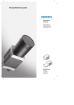
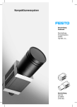
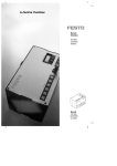
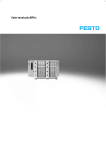
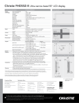
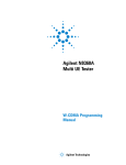
Compact Vision Systems SBOC-Q/SBOI-Q Compact Vision Systems SBOC-Q/SBOI-Q Key features Mode of operation The camera not only contains the sen sor system for image data acquisition, but also the complete electronic evaluation unit for image processing, an integrated PLC and the interfaces for communication with higher-level controllers. The CheckKon and CheckOpti software tools make configuring the image processing task very straightforward. The user creates reference images Evaluation modes Mode with the camera by presenting differ ent sample parts and then defines the desired inspection criteria. These can include, for example, brightness, distance, angle and circularity, but also the reading of text and/or 1D or 2D codes. The sample parts define the tolerance range, within which parts are identified as good, for each inspection characteristic. Up to 256 characteristics can be combined in a single program and up to 256 in spection programs can be stored on the camera. The camera can also be used to carry out sorting functions, as it is capable of storing and distinguishing between up to 16 different part types per inspection program. The characteristics calculated by the camera are not dependent on the rotary orientation and position of the Function inspection part, as they are deter mined relative to the position of the inspection part – any tilting and/or movement of the inspection part in the field of vision is therefore irrel evant for the inspection process. The behaviour of the camera during inspection is determined by the evalu ation mode. There are four different modes. Application Triggered Frame capture and inspection with each valid triggering signal. The triggering signal is generated by a master controller or a sensor as soon as the inspection part is in front of the camera. The inspection results are output following the inspection, and the camera then waits for the next valid triggering signal. Inspection of single parts when there is a triggering signal for image capture. Idle run with image trigger with Compact Vision System SBO…-Q-R…B Image capture is performed continu ously, but image evaluation only if there is an inspection part in front of the camera, i.e. if the trigger condition has been satisfied in a freely defined image area (e.g. a specific brightness is exceeded/fallen below). The inspec tion results are output following the inspection. The camera then waits for the next image-based trigger. Inspection of single parts at a medium to fast rate without an external sen sor. Idle run without image trigger Image capture and inspection (without fixed frame rate) are performed continuously. The triggering signal is permanently present, irrespective of whether or not there is an inspection part in front of the camera. The camera acts like a basic sensor. The inspection results are output following the inspection, and the camera then starts the next inspection immediately. Inspection of single or continuous parts at a medium to fast (continuous) rate. Fixed frame rate with Compact Vision Systems SBO…-Q-R1 and SBO…-Q-R2 Image capture and inspection are performed continuously at a defined frame rate. The triggering signal is permanently present. The inspection results are output following the in spection. The camera starts the next inspection in accordance with the defined frame rate. Inspection of continuous parts at a constant speed. The integrated PLC can be pro grammed in all programming languages covered by IEC 61131-3 (e.g. LDR, ST, sequential function chart, etc.) using the software tool CoDeSys provided by Festo. The prede fined function blocks enable straight forward data exchange between the image processing task and the integrated PLC. This provides an easy means of imple menting extensive inspection tasks or even communication between differ ent cameras. Programming Integrated PLC 2 è Internet: www.festo.com/catalog/... Subject to change – 2015/06 Compact Vision Systems SBOC-Q/SBOI-Q Key features Interfaces Connection and display components 5 4 3 1 2 Ethernet – TCP/IP Commissioning and diagnostics: – PC for configuration and for diagnostics with TCP/IP – Integration of the camera in a corporate network (integrated web server) 1 Fieldbus connection for Compact Vision Systems SBO…-Q-R1 and SBO…-Q-R2 2 Ethernet connection 3 Operating voltage supply and inputs/outputs 4 Adjusting screw for focus 5 Status LEDs: A Ready status B Ethernet traffic C Activity D Output Inputs: Camera trigger Error acknowledgment Outputs (can be parameterised): Ready status Good part correctly oriented Good part incorrectly oriented Reject part Error Warning External lighting Ethernet – TCP/IP, EasyIP, Telnet, Modbus TCP – Visualisation of the camera images and inspection results via SBO…-Q WebViewer All parameters can be modified and all inspection results and characteris tic values can be read via the Ethernet interface with EasyIP, Telnet and Modbus TCP. – Front End Display FED, e.g. for teach-in, status signals, type selection or parameter modification – Robot controllers and program mable logic controllers, e.g. CECX for reading characteristic values (e.g. coordinates and rotation angle) CANopen master functionality Servo controllers and remote I/O can be addressed directly via the CANopen master functionality. 2015/06 – Subject to change è Internet: www.festo.com/catalog/... 3 Compact Vision Systems SBOC-Q/SBOI-Q Key features Interfaces (continued) CAN – Vision system as CPI module For Compact Vision Systems SBO…-Q-R1 and SBO…-Q-R2 – The Compact Vision System SBO…-Q can be integrated into a Festo CPI network. In this case it functions like a binary module with 16 inputs and outputs. – In combination with a CPX-CPI module and a CPX bus node, for example, the camera can be accessed via PROFIBUS DP, INTERBUS, DeviceNet, CANopen, CC-Link, EtherNet/IP, PROFINET, POWERLINK, EtherCAT and Sercos III. CAN – I/O expansion For Compact Vision Systems SBO…-Q-R1 and SBO…-Q-R2 An input and output module can be connected to the camera via the camera’s CAN interface. – Input module CP-E08-M12-CL for binary preselection of the inspection program – Output module CP-A04-M12-CL for binary signalling of part types Using the CheckKon software, all processes within the camera – from image capture to the input and output parameters – can be displayed, logged and modified. This includes: – Selecting the evaluation mode – Displaying and editing system parameters – Displaying analysis of most recently inspected parts – Displaying and logging inspection part images and the characteristics derived from them – Loading new inspection programs – System documentation Software CheckKon 4 è Internet: www.festo.com/catalog/... Subject to change – 2015/06 Compact Vision Systems SBOC-Q/SBOI-Q Key features CheckOpti CheckOpti is used to configure inspec tion programs. Following the pres entation of sample parts, the user defines the characteristics to be inspected with the aid of the software. This is done by selecting the char acteristics from a list and then drag ging and dropping them to the area of the sample part to be inspected. A total of 256 performance characteris tics can thus be defined and opti mised within the framework of an in spection program. The inspection pro gram can then be uploaded to one of the camera’s 256 memory locations. Examples of inspection characteristics: – Vertical length measurement – Horizontal length measurement – Angle measurement – Counting of events – Measurements on the inspection part contour – Area definition – Calculation of grey tone or colour differences Application examples Quality inspection of tube with union nut The inspection takes place with back lighting; calculated characteristics: – Length of nut – Threaded coupling distances – Diameter of tube – Thread outside diameter – Angle measurement on the flange – Circumference of the screw – Area of the screw Screw type differentiation The inspection takes place with reflected light; calculated characteristics: – Centre of gravity coordinates x, y – Average grey tone of area – Angle of screw drive to horizontal 2015/06 – Subject to change è Internet: www.festo.com/catalog/... 5 Compact Vision Systems SBOC-Q/SBOI-Q Peripherals overview 4 1 3 2 5 6 7 Accessories Brief description è Page/Internet Compact Vision System 1 SBOC-Q-… 2 SBOI-Q-… For standard lenses with C mount or CS mount1) connection With integrated lens and light 8 Plug socket with cable 3 SIM-M12-8GD-…-PU For supplying the operating voltage 15 Cable 4 SBOA-K30E-M12S – SBOA-K20CP-WS – SBOA-K20CP-SUP Ethernet diagnostic cable For integration in a CPI system For I/O expansion 15 Lens – SASF-C-L-F… Focal length 6 … 35 mm 14 Mounting attachments 5 Adapter kit SBOA-HMSV-39 6 Adapter kit SBOA-HMSV-40 7 Adapter kit SBOA-HMSV-41 – Adapter SBOL-C-5 With screw-on adapter plate Without screw-on adapter plate With female thread G¼ for mounting on commercially available tripods 5 mm spacer ring (CS mount to C mount) 13 1) 6 13 CS mount without protective tube. è Internet: www.festo.com/catalog/... Subject to change – 2015/06 Compact Vision Systems SBOC-Q/SBOI-Q Type codes SBO C – Q – R3 B – – S1 Function SBO Compact Vision System Design For standard lenses with C mount or CS mount1) connection Integrated lens C I Equipment Q Field-based camera for quality inspection Sensor resolution R1 R3 R2 640 x 480 pixels, VGA resolution 752 x 480 pixels, Wide VGA resolution 1,280 x 1,024 pixels, SXGA resolution Sensor type B C Monochrome Colour Fieldbus interface WB CAN interface Without fieldbus interface Application S1 1) Tools add-in CS mount without protective tube. 2015/06 – Subject to change è Internet: www.festo.com/catalog/... 7 Compact Vision Systems SBOC-Q/SBOI-Q Technical data -P-Q- Voltage 24 V DC Temperature range –10 … +50 °C General technical data Type Sensor resolution Exposure time Frame rate (full image) Sensor type [pixels] [ms] [fps] Lens mounting Operating distance [mm] Field of vision [mm] Max. no. of inspection programs Max. no. of orientations Sorting function 1) Nominal operating voltage Permissible voltage fluctuations Current consumption with load-free outputs Max. residual current Input 1 Input 2 Outputs Protection class 8 SBOI-Q-R1 0.039 … 1,000 150 Monochrome C mount Integrated lens CS mount1) Dependent on the 22 … 1,000 lens selected Dependent on the 14x10 … 520x390 lens selected 256 8 per part type Up to 16 types per inspection program SBOC-Q-R3 752 x 480 SBOI-Q-R3 0.018 … 200 60 Monochrome Colour C mount CS mount1) Dependent on the lens selected Dependent on the lens selected 256 8 per part type – Integrated lens 20 … 550 7.9x5.5 … 195x125 SBOC-Q-R2 1,280 x 1,024 0.008 … 1,000 27 Monochrome Colour C mount CS mount1) Dependent on the lens selected Dependent on the lens selected 256 8 per part type Up to 16 types per inspection program Without protective tube. Electrical data Type 1) SBOC-Q-R1 640 x 480 SBOC-Q [V DC] [%] 24 ±10 [mA] 120 [A] 1.5 at the 24 V outputs Trigger signal Used by CoDeSys Applying inputs Acknowledging errors Used by CoDeSys Good part Reject part Warning Error External lighting Used by CoDeSys IP65, IP671) SBOI-Q IP65, IP67 Only in combination with protective tube (included in the scope of delivery). è Internet: www.festo.com/catalog/... Subject to change – 2015/06 Compact Vision Systems SBOC-Q/SBOI-Q Technical data Electrical data Type Sensor resolution Ethernet interface Bus interface Connection technology Data transmission speed Supported protocols [pixels] [Mbps] Fieldbus interface Type Connector plug Supported protocols SBO…-Q-R1 640 x 480 SBO…-Q-R3 752 x 480 SBO…-Q-R2 1,280 x 1,024 – CAN Plug M12 CP fieldbus IEEE802.3U (100BaseT) Plug M12 100 TCP/IP EasyIP Telnet ModbusTCP CAN Plug M12 CP fieldbus Operating and environmental conditions Ambient temperature Storage temperature Ambient conditions [°C] [°C] CE mark (see declaration of conformity)1) Certification 1) –10 … +50 –10 … +60 Screened from extreme external light sources Cleanest possible ambient air In accordance with EU EMC Directive c UL us Recognized (OL) C-Tick For information about the applicability of the component see the manufacturer’s EC declaration of conformity at: www.festo.com/sp è User documentation. If the component is subject to restrictions on usage in residential, office or commercial environments or small businesses, further measures to reduce the emitted interference may be necessary. Materials Housing Cap Note on materials Anodised aluminium ABS, fibre glass reinforced Free of copper and PTFE RoHS-compliant Weight [g] Lens mounting Type C mount/CS mount1) SBOC-Q-R1 SBOC-Q-R3 SBOC-Q-R2 Integrated lens SBOI-Q-R1 SBOI-Q-R3 Compact Vision System 182 172 182 184 174 1) CS mount without protective tube. 2015/06 – Subject to change è Internet: www.festo.com/catalog/... 9 Compact Vision Systems SBOC-Q/SBOI-Q Technical data Download CAD data è www.festo.com Dimensions C mount/CS mount1) SBOC-Q-R1/-R2 1 Power supply and inputs/ outputs 2 Ethernet connection 3 Bus connection 4 Protective tube C mount/CS mount1) SBOC-Q-R3 1 Power supply and inputs/ outputs 1) 2 Ethernet connection 4 Protective tube CS mount without protective tube. Type B1 B3 B4 B5 B6 D1 H1 H3 H4 H5 H6 H7 H8 H9 L1 L2 L3 L4 L5 SBOC-Q-R1/-R2 SBOC-Q-R3 45 13.91 42.2 18.8 1.4 45 45 24.65 1.15 2 0.3 21.8 19.8 – 1.4 139.4 139 71 85.4 85 50 1.7 1.3 10 è Internet: www.festo.com/catalog/... Subject to change – 2015/06 Compact Vision Systems SBOC-Q/SBOI-Q Technical data Download CAD data è www.festo.com Dimensions Integrated lens SBOI-Q-R1 1 Power supply and inputs/ outputs 2 Ethernet connection 3 Bus connection Integrated lens SBOI-Q-R3 1 Power supply and inputs/ outputs 2 Ethernet connection Type B1 B2 B3 B4 B5 B6 H1 H2 H3 H4 H5 H6 H7 H8 H9 L1 L2 SBOI-Q-R1 SBOI-Q-R3 45 30.2 13.91 42.2 18.8 1.4 45 35 24.65 1.15 2 0.3 21.8 19.8 – 1.4 83.7 71 2015/06 – Subject to change è Internet: www.festo.com/catalog/... 11 Compact Vision Systems SBOC-Q/SBOI-Q Technical data Ordering data Sensor type Part No. Type 640 x 480 pixels, VGA resolution For standard lenses with C mount or CS mount1) connection Monochrome Integrated lens Monochrome 541399 569771 541396 569773 SBOC-Q-R1B SBOC-Q-R1B-S1 SBOI-Q-R1B SBOI-Q-R1B-S1 752 x 480 pixels, Wide VGA resolution For standard lenses with C mount or CS mount1) connection Monochrome 555841 569777 555842 569778 555839 569779 555840 569780 SBOC-Q-R3B-WB SBOC-Q-R3B-WB-S1 SBOC-Q-R3C-WB SBOC-Q-R3C-WB-S1 SBOI-Q-R3B-WB SBOI-Q-R3B-WB-S1 SBOI-Q-R3C-WB SBOI-Q-R3C-WB-S1 551021 569772 551022 SBOC-Q-R2B SBOC-Q-R2B-S1 SBOC-Q-R2C Colour Integrated lens Monochrome Colour 1,280 x 1,024 pixels, SXGA resolution For standard lenses with C mount or CS mount1) connection Monochrome For standard lenses with C mount or CS mount1) connection Colour 1) 12 CS mount without protective tube. è Internet: www.festo.com/catalog/... Subject to change – 2015/06 Compact Vision Systems SBOC-Q/SBOI-Q Accessories Adapter kit SBOA-HMSV-39 with screw-on adapter plate Material: Anodised wrought aluminium alloy Ordering data Adapter kit Part No. Type 541599 SBOA-HMSV-39 Part No. Type 541600 SBOA-HMSV-40 Part No. Type 542140 SBOA-HMSV-41 Part No. Type 541601 SBOL-C-5 Adapter kit SBOA-HMSV-40 without screw-on adapter plate Material: Anodised wrought aluminium alloy Ordering data Adapter kit Adapter kit SBOA-HMSV-41 with female thread G¼ for mounting on commercially available tripods Material: Anodised wrought aluminium alloy Ordering data Adapter kit Adapter SBOL-C-5 5 mm spacer ring (CS mount to C mount) Material: Anodised wrought aluminium alloy Ordering data Adapter 2015/06 – Subject to change è Internet: www.festo.com/catalog/... 13 Compact Vision Systems SBOC-Q/SBOI-Q Accessories Lens SASF-C-L-F6 Focal depth 6 mm Note on materials: Contains PWIS (paint wetting impairment substances) RoHS-compliant Lens SASF-C-L-F16 Focal depth 16 mm Note on materials: Contains PWIS (paint wetting impairment substances) RoHS-compliant Lens SASF-C-L-F12/25/35 Focal depth 12/25/35 mm Note on materials: Contains PWIS (paint wetting impairment substances) RoHS-compliant Dimensions Type SASF-C-L-F6 SASF-C-L-F16 SASF-C-L-F12 SASF-C-L-F25 SASF-C-L-F35 D1 D2 D3 D4 D5 L1 L2 L3 L4 32 29.5 29 28.5 – 27, P=0.5 1-32UN 1-32UN-2A 22.5 – 6.5 – 28.5 27, P=0.5 1-32UN-2A 1.9 – 7.1 6.9 6 4 4 29.5 37.5 33.2 28.5 32 35.4 4 – 16.5 19.5 Ordering data – Lenses Operating distance [mm] Focal depth C mount for Compact Vision System with sensor resolution R1 and R3 200 6 572910 SASF-C-L-F6 -V- C mount for Compact Vision System with sensor resolution R1 and R3 250 12 572911 SASF-C-L-F12 -V- C mount for Compact Vision System with sensor resolution R1, R2 and R3 250 16 25 35 572912 572913 572914 SASF-C-L-F16 SASF-C-L-F25 SASF-C-L-F35 -V-V-V- 350 14 Technical data è Internet: sasf-c Part No. Type Brief description è Internet: www.festo.com/catalog/... [mm] Subject to change – 2015/06 Compact Vision Systems SBOC-Q/SBOI-Q Accessories Ordering data Use Connection Cable length [m] For supplying the operating voltage Straight socket, M12x1, 8-pin Open end, 8-pin 2 Technical data è Internet: sim-m12 525616 SIM-M12-8GD-2-PU 5 525618 Plug socket with cable Cable Part No. Type SIM-M12-8GD-5-PU Technical data è Internet: sboa 542139 SBOA-K30E-M12S Ethernet diagnostic cable Straight socket, M12x1, 4-pin, D-coded 3 RJ45 plug For integration in a CPI system Straight socket, M12x1, 5-pin Angled plug, M9x0.5, 5-pin 2 548823 SBOA-K20CP-WS For I/O expansion Straight socket, M12x1, 5-pin Straight socket, M9x0.5, 5-pin Straight plug, M12x1, 4-pin 2 548824 SBOA-K20CP-SUP Ordering data – Documentation Brief description Language Part No. Type Manual User manual in paper form is not included in the scope of delivery for the Compact Vision System German 548318 P.BE-SBO-Q-DE English 548319 P.BE-SBO-Q-EN Documentation package User manual on CD-ROM is included in the scope of delivery for the Compact Vision System German, English 549036 P.BE-SBO-Q-UDOK Language Part No. Type German, English 194496 P.SW-KON CheckOpti software 568339 P.SW-OPTI SBO...-Q Tools add-in software licence for unlocking tools on the Compact Vision System 570045 GSLO Ordering data – Software Brief description CheckKon software 2015/06 – Subject to change è Internet: www.festo.com/catalog/... 15 Product Range and Company Overview A Complete Suite and Company Overview Our experienced engineers provide complete support at every stage of your development process, including: conceptualization, analysis, engineering, design, assembly, documentation, validation, and production Custom Automation Components Complete custom engineered solutions Custom Control Cabinets Comprehensive engineering support and on-site services Complete Systems Shipment, stocking and storage services The Broadest Range of Automation Components With a comprehensive line of more than 30,000 automation components, Festo is capable of solving the most complex automation requirements Electromechanical Electromechanical actuators, motors, controllers & drivers Pneumatics Pneumatic linear and rotary actuators, valves, and air supply P/Cs and ,O 'evices PLC’s, operator interfaces, sensors and I/O devices To meet this commitment, we strive to ensure a consistent, integrated, and systematic approach to management that will meet or exceed the requirements of the ISO 9001 standard for Quality 0anagement and the ISO 1001 standard for (nvironmental 0anagement ISO 9001 ISO 14001 &HUWLÀHG Company &(57&$$4(617*$ 4ualit\ Assurance ,SO and ,SO Certiącations Festo Corporation is committed to supply all Festo products and services that will meet or exceed our customersn reTuirements in product Tuality, delivery, customer service and satisfaction &(57&$4(617*$ Supporting Advanced Automation… As No One Else Can! Festo is a leading global manufacturer of pneumatic and electromechanical systems, components and controls for industrial automation, Zith more than , employees in national headTuarters serYing more than countries For more than years, Festo has continuously elevated the state of manufacturing with innovations and optimized motion control solutions that deliver higher performing, more proątable automated manufacturing and processing eTuipment 2ur dedication to the advancement of automation extends beyond technology to the education and development of current and future automation and robotics designers with simulation tools, teaching programs, and onsite services Copyright 01, Festo Corporation :hile every effort is made to ensure that all dimensions and speciącations are correct, Festo cannot guarantee that publications are completely free of any error, in particular typing or printing errors $ccordingly, Festo cannot be held responsible for the same For /iability and :arranty conditions, refer to our oTerms and Conditions of Salep, available from your local Festo ofące $ll rights reserved 1o part of this publication may be reproduced, distributed, or transmitted in any form or by any means, electronic, mechanical, photocopying or otherwise, without the prior written permission of Festo $ll technical data subMect to change according to technical update Printed on recycled paper at 1ew +orizon *raphic, Inc, FSC certiąed as an environmental friendly printing plant Festo North America 1 Festo Canada Headquarters Festo Inc. 5300 Explorer Drive 0ississauga, O1 LW 5* 2 Montréal 5600, Trans-Canada Pointe-Claire, QC +95 1%6 3 Québec City 930, rue Watt11 Québec, QC *1; *3 4 Festo United States Headquarters Festo Corporation 395 Moreland Road +auppauge, 1< 11 5 Appleton 1orth 9 Tower 9iew Drive, Suite 1 Greenville, WI 59 7 'etroit 11 West Long Lake Road Troy, MI 09 6 Chicago 5 W Algonquin - Suite 30 Arlington +eights, IL 60005 8 Silicon Valley 935 Southfront Road, Suite F Livermore, CA 9550 Canadian Customers Commercial Support: Tel: 1 *O FESTO 1 3 3 Fax: 1 F; FESTO 1 393 3 Email: festocanada#cafestocom Technical Support: Tel:1 *O FESTO 1 3 3 Fax:1 F; FESTO1 393 3 Email: technicalsupport#cafestocom USA Customers Commercial Support: Tel:1 00 99 FESTO 1 00 993 3 Fax:1 00 9 FESTO 1 00 93 3 Email: customerservice#usfestocom Technical Support: Tel:1 *O FESTO 1 3 3 Fax:100 9 FESTO1 00 93 3 Email: productsupport#usfestocom SubMect to change Internet: www.festo.com/us C Festo Regional Contact Center