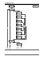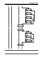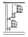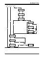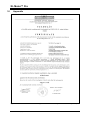
1
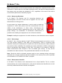
User’s Manual
Inventure
XL Meter
™
Pro Gamma
XL Meter™ Pro
Notes
XLMPUSREN73– page 2
© Inventure Automotive Electronics R&D, Inc.
XL Meter™ Pro
Table of content
1
2
3
INTRODUCTION...............................................................................................................................4
WARRANTY .....................................................................................................................................4
PARTS CHECK LIST........................................................................................................................4
3.1 OPTIONAL COMPLEMENTARY ..........................................................................................................5
4 DESCRIPTION..................................................................................................................................5
4.1 DEFINITION OF XL METER™ ..........................................................................................................5
4.2 OUTLOOK ......................................................................................................................................5
4.3 FUNCTIONAL DESCRIPTION .............................................................................................................9
4.4 BATTERY INSTALLATION/REPLACEMENT ........................................................................................ 27
4.5 PC CONNECTION ........................................................................................................................ 28
4.6 XL VISION™ DATA UPLOAD AND EVALUATION PROGRAM ................................................................ 28
4.7 PC CRASH COMPATIBILITY .......................................................................................................... 31
5 SYSTEM CHARACTERISTICS ..................................................................................................... 32
5.1 ABSOLUTE MAXIMUM RATINGS ..................................................................................................... 32
5.2 TECHNICAL DATA ........................................................................................................................ 32
5.3 MFDD CALCULATION .................................................................................................................. 32
6 HOW TO MEASURE WITH XL METER™? .................................................................................. 33
6.1 DETAILED DESCRIPTION OF THE MEASUREMENT PROCESS ............................................................. 33
6.2 EVALUATING SERVICE BRAKE PERFORMANCE .............................................................................. 34
6.3 ACCELERATION EVALUATION........................................................................................................ 35
7 DISPLAY MESSAGES .................................................................................................................. 36
7.1 OPERATION MESSAGES .............................................................................................................. 36
7.2 WARNING MESSAGES .................................................................................................................. 36
7.3 ERROR MESSAGES ...................................................................................................................... 36
7.4 ERROR CODES ........................................................................................................................... 37
7.5 PLAUSIBILITY ERROR CODES ....................................................................................................... 37
8 CERTIFICATION/CALIBRATION.................................................................................................. 38
8.1 TEST BY THE TECHNICAL UNIVERSITY OF BUDAPEST .................................................................... 38
8.2 TEST BY AN OMH ACCREDITED LABORATORY ............................................................................... 38
8.3 CALIBRATION .............................................................................................................................. 39
9 HOW TO CONTACT INVENTURE?.............................................................................................. 41
10 APPENDIX ..................................................................................................................................... 42
© Inventure Automotive Electronics R&D, Inc.
XLMPUSREN73 – page 3
XL Meter™ Pro
1 Introduction
Thank you for purchasing an Inventure product. Your new XL Meter™ Pro 1 is a carefully
engineered, high quality durable product with modern features and elegant styling. It is
designed to give you the quality and convenience you expect from an
acceleration/deceleration meter.
To familiarize yourself with all the features of your instrument, please read the following
instructions carefully. Retain this guide for future reference. 2
Important! All the information written in this material is informative and subject to changes
without any notice.
2 Warranty
There is a one-year warranty on XL Meter™ from the date of the original purchase. The
warranty covers any defect in materials or workmanship. The warranty is valid only if XL
Meter™ was operated under normal circumstances in regular use and the warranty sealing is
not corrupted. The warranty does not include the batteries, damage from misuse or neglect.
As XL Meter™ has a well thought design, it is thoroughly tested before release and it is
composed of high quality parts, there should be no need for regular maintenance of any
parts of XL Meter™ during normal operation. Therefore the box screws are sealed. Should
the seal be missing, damaged or corrupted, the warranty for XL Meter™ is no longer valid.
Remember to save your sales receipt (invoice) in case you ever need warranty service.
Please refer to the serial number of your XL Meter™ in case of any problems. The serial
number can be found on a label inside the battery compartment or can be displayed in
Settings mode.
In case of warranty claims contact your local dealer or directly Inventure, Inc. (See Section 9)
3 Parts check list
Check this list to be certain all components are included.
•
XL Meter™ base unit
•
Special bag
•
RS-232 link cable
1
The Inventure logo and name, XL Meter and XL Vision are trademarks of Inventure, Inc. and are protected by copyright law.
Copyright by Inventure, Inc. 1997-2002. All rights reserved.
2
Information contained in this publication regarding the device applications and the like is intended through suggestion only and
may be superseded by updates.
XLMPUSREN73– page 4
© Inventure Automotive Electronics R&D, Inc.
XL Meter™ Pro
3.1
•
Set of AA type batteries (4 pieces)
•
CD with XL Vision™ software
Optional complementary
The XL Meter™ universal acceleration end deceleration set contains everything that
necessary form normal usage. With the help of the optional complementary, which are not
included, the usage of the instrument can be even more comfortable. The list of the optional
complementary can be read on the homepage of Inventure Automotive. Among them are the
followings:
•
Brake pedal switch – for brake delay examination
•
USB cable kit – for perfect USB connection
•
Cigar-lighter adapter – for continuous readiness in cars
4 Description
4.1
Definition of XL Meter™
XL Meter™ is a battery operated universal acceleration/deceleration meter with an
alphanumeric LCD display, built-in service brake performance or acceleration evaluation
program, and RS-232 compatible PC interface.
4.2
Outlook
From technical viewpoint the design of XL Meter™ is composed of three parts. These are the
housing containing the electronic control unit, the vacuum cup and the jointed arm for flexible
suspension.
4.2.1
Box
XL Meter™ has an aluminium box specially designed to be suitable, easy to handle and easy
to install for acceleration measurement purposes. The jointed arm on the top enables the
calibration of the zero level when installed on the windscreen by the vacuum cup. Under the
bottom cover the AA type battery holder can be found. (See detailed in chapter 4.4)
4.2.2
Connectors
There are two connectors on the back panel of XL Meter™. The nine-pole SUB-D type is the
RS-232 compatible interface connector that enables communication to a PC. The PC link
cable (supplied) should be connected here during data upload. The same connector is used
for the input of the brake pedal switch and the output of the trigger signal.
© Inventure Automotive Electronics R&D, Inc.
XLMPUSREN73 – page 5
XL Meter™ Pro
Table 1
The pin assignment of the nine-pole D-SUB connector
Pin
Name
Description
1
-
-
2
RX
RS-232 receive
3
TX
RS-232 transmit
4
Brake Trigger Input 1
Brake Trigger Input 1
5
GND
System Ground
6
Trigger Out
Trigger Output
7
-
(Optional) Analogue Input
8
Brake Trigger Input 2
Brake Trigger Input 2 (Optional)
9
-
(Optional) VCC
The round one is the external power supply (DC in) connector. Use only approved external
adapter for powering XL Meter™. The housing of XL Meter™ is negative grounded, the
pinout of the external power supply connector can be seen on Figure 1.
Figure 1
The pinout of the external power supply connector
Note: The maximum input voltage allowed is 18.0V.
4.2.3
Suspension
XL Meter™ can be installed in seconds, due to its suitable design of suspension. XL Meter™
is suspended by a high quality vacuum cup. Simply putting XL Meter™ to the desired point of
the windscreen or any other fine surface and turning the knob of the vacuum cup is sufficient
for a strong installation. Due to the high quality of the Veribor® vacuum cup, XL Meter™ has
a particularly strong hold on the surface where it was installed.
4.2.4
Control buttons
XL Meter™ is extremely simple to operate. Three buttons can operate it. Each button has a
different color and a dedicated function described below:
4.2.4.1 On/Off Button (Black Button)
The On/Off button has two functions: the first is to control the power supply, and the second
is to control the backlight or the brightness of the display. If the XL Meter™ is off, you can
XLMPUSREN73– page 6
© Inventure Automotive Electronics R&D, Inc.
XL Meter™ Pro
switch it on by pressing the On/Off button once for a couple of seconds. After switching on,
pressing the On/Off Button for a short period of time (less than 2 sec.) will result in toggling
the backlight or the brightness of the display (depending on the type of the display: LCD or
PLED). This means that the backlight/brightness will turn on or increase by pressing the
button once, and turn off or decrease by pressing it for the second time, turn on or increase
also for the third time, and so on. It is important to note that the LCD backlight should only be
used when it is necessary, as the power consumption is approximately tripled if the LCD
backlight is on, resulting in shorter battery lifetime. XL Meter™ can be switched off by
pressing the On/Off button for a longer period of time (more than 2 seconds). If this action is
successful you see a shutdown message on the screen before releasing the button.
4.2.4.2 Display Button (Green Button)
The results of all measurements can be displayed on the screen by pressing the green
button. From Calibration Mode you can enter Display Mode by pressing once either the
green or the red button.
In Display Mode you can switch from one measurement to another by pressing the display
button. You do not have to wait until all the results are displayed, but you can anytime
interrupt one display cycle and enter the display cycle of the next measurement.
You can start a measurement (data acquisition) by pressing the red button. To stop data
acquisition press the display (green) button. The evaluation automatically (if such evaluation
was chosen) starts after the stoppage the measurement. Finishing the evaluation it enters
Display Mode again and the currently performed measurement results will be displayed.
4.2.4.3 Measurement Button (Red Button)
Starting a measurement (data acquisition) can be invoked by the measurement button. You
can also use the red button to enter Display Mode from Calibration Mode by pressing it once.
Measurement can only be started from Display Mode. Anytime the currently displayed
measurement will be overwritten by the new measurement. You do not have to wait until all
the results are displayed, but you can anytime interrupt one display cycle and start data
acquisition. Data acquisition can be stopped by the display (green) button.
Note: Before starting measuring, the XL Meter™ Pro Gamma will ask to overwrite the actual
measurement. If yes, then the measurement starts, if No, it returns to Display Mode. In this
way, you can avoid to overwrite a measurement accidentally.
4.2.5
Display
The display is a 2x16 character alphanumeric display; it features high contrast easy to read
characters and numbers. There are two kinds of displays depending on the technology:
Liquid Crystal Display (LCD) with switchable backlight and PLED with switchable brightness.
© Inventure Automotive Electronics R&D, Inc.
XLMPUSREN73 – page 7
XL Meter™ Pro
4.2.5.1
LCD
There is a possibility to illuminate the LCD during night measurements. The LCD backlight
can be toggled (turned on/off) by simply pressing the On/Off button (See details in
chapter 4.2.4.1).
Note: The LCD backlight consumes relatively high energy, meaning that the continuous
usage of the LCD backlight can radically reduce the battery lifetime. So please make sure
that the light is off when it is not necessary.
4.2.5.2 PLED
The PLED display uses yellow-green pixels to show characters. While the LCD display has
switchable backlight, the PLED display has switchable brightness. Due to the production
technology, the PLED display has outstanding brightness and contrast. Its brightness can be
disturbing especially in darkness so its brightness can be increased and decreased by
pushing the On/Off button for a short time (See details in chapter 4.2.4.1).
4.2.6
Buzzer
The XL Meter™ Pro Gamma has an integrated Buzzer. With the Buzzer’s signal, it is easier
to realise the different states of the instrument. The Buzzer can be turned on and off in the
Settings/Special settings/Buzzer menu.
The default setting of the Buzzer is on, and the Measuring mode is signed by cheeping
continuously. This cheeping can be turned off temporally (and turned on again) by pressing
the Red button for approx. 1 second.
Note: In Measuring mode, toggling the Buzzer is temporally only and is not saved. For the
next measurement, the Buzzer state set in Settings menu will be valid.
XLMPUSREN73– page 8
© Inventure Automotive Electronics R&D, Inc.
XL Meter™ Pro
Table 2
Meanings of Cheeping
Event
Cheeping
Turn On / Off
1
System test OK
1
Press Display (green) button
1
Press Measuring (red) button a
1
Measuring
Continuous
End of measurement
1
Evaluation error
3
Change settings / write memory
1
Battery low
5
Change batteries
5
4.3
Functional description
4.3.1
Power-on
You can turn on XL Meter™ by pressing the black On/Off button for approx. 2 seconds (See
detailed in chapter 4.2.4.1). Short button press will not turn the instrument on; this feature
prevents the instrument from turning on unintentionally or accidentally. When the instrument
is turned on, it cheeps one to sign (See chapter 4.2.6 for details), and then the instrument
name (XL Meter Pro Gamma) is displayed in the first line of the display for identification
purpose. At power-on, the LCD backlight is turned on while the system is checked internally
for errors and the battery performance is evaluated. If the are no problems the System Check
OK message can be read on the display. After this the backlight is turned off automatically
and XL Meter™ enters Calibration Mode.
4.3.2
Calibration Mode
Entering Calibration Mode is automatic after System Check. In Calibration Mode the
component of the gravity acceleration (≈9.8 m/s2) in line with the sensing axis of XL Meter™
can be read on the display with 0.1s refresh rate. Calibration Mode has tree purposes: In
calibration mode both the longitudinal (ax) and lateral (ay) acceleration components are
displayed simultaneously. The objectives of calibration:
•
After installation - before starting a measurement - XL Meter™ has to be set to the
0.0m/s2 calibration level. This procedure was implemented in order to have
maximum resolution during measurement.
•
Sensor test possibility. (See detailed in chapter 4.3.2.1)
© Inventure Automotive Electronics R&D, Inc.
XLMPUSREN73 – page 9
XL Meter™ Pro
4.3.2.1 Sensor Test
This function is a perfect possibility to test the measuring capabilities of XL Meter™, as the
user is able to test the performance of the acceleration sensor. The sensor test can easily be
performed using the earth’s gravity as an etalon. Turning the sensitive axis of XL Meter™ to
the ground, in ideal case the well-known 9.8 m/s2 should be seen, and turning XL Meter™
upside down with 180 degrees -9.8 m/s2 should be seen on the display.
To be able to decide whether the actual performance of the sensor enables to take correct
(legally and technically acceptable) measurements or not, the calibration status of the
instrument should be determined. (See chapter 8.3)
Note: After power-on the acceleration sensor may require some seconds to “warm-up” and
show the correct value.
4.3.3
Display Mode
Entering Display Mode automatically starts the display cycle that shows the measurement
results. XL Meter™ starts the display of the measurement results with the one that was
active before power-off. The displayed measurement results under each measurement
number are always the results of the last successfully evaluated measurement.
If there was an evaluation error, there is no display cycle of measurement results, but the
evaluation error code is displayed under the corresponding measurement number. The
meaning of the error codes are listed in chapter 7.4.
Note: Regardless of the fact of an evaluation error the measured data are stored, thus they
can be uploaded to the PC for manual evaluation.
From Calibration Mode you can enter Display Mode by pressing either the green or the red
button once. In Display Mode you can switch from one measurement to another by pressing
the display (green) button. You do not have to wait until all the results are displayed, but you
can anytime interrupt one display cycle and enter the display cycle of the next measurement.
You can start a measurement (data acquisition) by pressing the red button. Data acquisition
can be stopped by pressing the display (green) button. Stopping the measurement the
device returns to display mode, where the actual measurement results are displayed. The
results are scrolling on the display continuously, thus the results can be easily noted. The
results are depending from the type of the measurement. The detailed explanation of the
different evaluations and results can be found at chapter 4.3.5
XLMPUSREN73– page 10
© Inventure Automotive Electronics R&D, Inc.
XL Meter™ Pro
4.3.4
Measurement – data acquisition
4.3.4.1 Acceleration measurement
XL Meter™ uses a complete acceleration measurement system on a single monolithic IC. It
contains a polysilicon surface-micromachined sensor and signal conditioning circuitry which
implements a force-balance control loop. XL Meter™ is capable of measuring both positive
and negative acceleration to a maximum level of ±2 g. The characteristic of the acceleration
sensor assures the quality of the measurement results.
4.3.4.2 Acceleration sensor
XL Meter™ uses a differential capacitor acceleration sensor. The differential capacitor
acceleration sensor consists of independent fixed plates and central plates attached to the
main beam that moves in response to an applied acceleration.
The two capacitors are series connected, forming a capacitive divider with a common
movable central plate. When at rest, the values of the two capacitors are the same, and
therefore, the voltage output at their electrical centre is zero. When acceleration is applied,
the common central plate moves closer to one of the fixed plates while moving further from
the other. This creates a mismatch in the two capacitances, resulting in an output signal at
the central plate. The output amplitude of the signal varies directly with the amount of
acceleration experienced by the sensor. You can simply check the performance of the
acceleration sensor in Calibration Mode. (See detailed in sections 4.3.2 and 8.3)
Note: Right after power-on the acceleration sensor may require some seconds to “warm-up”
and show the correct value.
Note: The maximum shock survived by the acceleration sensor for 0.5ms is 500g in
powered, and 1000g in unpowered status. Remember that drops onto hard surface can
cause shocks of greater than 1000g, so care should be taken in handling XL Meter™ to
avoid this damage.
4.3.4.3 Data acquisition
The XL Meter™ Pro Gamma is designed to measure the acceleration in two axis
(longitudinal an lateral) Measuring Mode (data acquisition) can only be started from Display
Mode by pressing the red button. Since you have started data acquisition the acceleration
data are stored in the memory. No matter how long you drive in Measuring Mode before
braking, in each case the last 40 (80) 3 seconds of measured data are available in the
memory. You cannot switch off the XL Meter™ during data acquisition. The display button is
the only button that has effect on the measurement cycle, pressing it will stop data
acquisition.
3
The measuring time depends on the Measurement number and the Measuring frequency
© Inventure Automotive Electronics R&D, Inc.
XLMPUSREN73 – page 11
XL Meter™ Pro
Note: Data acquisition and on-the-spot evaluation are independent, separate functions of the
instrument. It means that due to the data acquisition theory, the data are always stored into
the memory and can always be uploaded to a PC, regardless of the result of the built-in
service brake performance evaluation program.
4.3.4.4 Measuring Directions
In XL Meter™ Pro Gamma, the X-Y measuring directions are
interchangeable, and each of them can be negated. You can reach
these features in Settings menu.
In some cases (e.g. broken windscreen), it can be useful to install the
equipment in some other places than the recommended one (the
middle of the windscreen). In these cases, interchanging the
measuring directions and/or negating them can be very useful. After
proper settings, the acceleration or deceleration measurement is
possible even installing the equipment on one of the side windows.
Example: installing the equipment in the back windscreen, both directions must be negated.
4.3.4.5 Data storage
XL Meter™ has a storing capacity of eight 4 different measurements and results at a time.
The data storage capacity is 40s (80s) per measurement. There is continuous data
acquisition during one measurement so anytime the last 40 (80) seconds of data measured
are stored for future availability. The sampling rate of the acceleration is 200Hz, meaning that
there is acceleration data available in every 5ms. The battery is not needed to retain the
stored measurement data, because of the non-volatile type memory, so they will be
accessible even after shut down. The guaranteed data retention is over 200 years.
Note: Should the built-in evaluation program send an error message during on-the-spot
evaluation the currently measured data are available in the memory, thus can be uploaded
and evaluated on a PC with the XL Vision™ program.
4.3.4.6 Measurement identifier
In XL Meter™ Pro Gamma, each measurement has a unique identifier. This is a number
incremented by one at each measurement, so the actual measurement identifier also can tell
how many measurements were carried out altogether.
4
Three, six or eight different measurements are available depending on the configuration
XLMPUSREN73– page 12
© Inventure Automotive Electronics R&D, Inc.
XL Meter™ Pro
4.3.5
On-the-spot evaluation
XL Meter™ has several built-in evaluation programs to enable fast on-the-spot evaluation of
service brake performance or acceleration. The type of evaluation can be chosen in Settings
menu and it must be chosen prior to starting the measurement. For a measurement, only one
on-the-spot evaluation can be chosen, but if you upload the measured data to a PC, the
same measurement can be evaluated in different ways.
Available On-the-spot evaluations:
•
No Evaluation (optional):
Only
data
acquisition
is
performed.
Useful
for
measurements with no built-in evaluation.
•
Service Brake Evaluation (default): After finishing data acquisition, this evaluation is
started automatically. The evaluation is used to qualify the vehicle service brakes.
Useful for on-the-spot investigation of accidents, creation of forensic engineering
reports on accidents, the task of service brakes testers.
•
Acceleration Evaluation (optional):
The evaluation running parallel with acquisition
is used to analyse the vehicle acceleration and dynamic. Useful for journalists of
motoring or car/motor mechanics, drag race and tuning fans.
•
Retarder Evaluation (optional):
For the moment, it can be performed only in PC,
but in the future, it will be available as a built-in feature.
•
Tram Brake Evaluation (default):
For the moment, it can be performed only in PC,
but in the future, it will be available as a built-in feature.
4.3.5.1 Service Brake Evaluation
XL Meter™ has a built-in evaluation program to enable fast on-the-spot evaluation of service
brake performance. The built-in evaluation program is valid for the automatic evaluation of
braking performed by the service brake. (This built-in evaluation program facilitates on-thespot investigation of accidents, creation of forensic engineering reports on accidents, the task
of service brakes testers, etc.)
As the built-in service brake performance evaluation program starts automatically right after
finishing a measurement.
Important! After the vehicle has stopped and the vehicle reaches absolute standstill, the
user has to wait approximately one second before pushing the display button and terminating
data acquisition. XL Meter™ then automatically starts the evaluation procedure. First, it
learns the standstill level that will be the base level for further calculations.
Note: Pushing the display button earlier will result in an evaluation error, see chapter 7.
© Inventure Automotive Electronics R&D, Inc.
XLMPUSREN73 – page 13
XL Meter™ Pro
The brake start time and brake end time of the deceleration process is determined based on
the measured characteristics. The braking time (Tbr) is calculated by subtracting the brake
start time from the brake end time. The initial vehicle speed value is calculated by the simple
numerical integration of the acceleration data in the interval of the brake time. Brake distance
(So) is calculated by the duplicate integration of the acceleration data in the interval of the
brake time. The calculation method of ‘MFDD’ is described section 5.3. The successful
evaluation gives the following results.
•
So [m] distance in the time of braking (Tbr)
•
Vo [km/h] initial vehicle speed at the time of braking
•
Tbr [s] time from the start till the end of braking
•
MFDD [m/s2] is a standard measurement number described in ECE Regulation
No. 13. (European Braking Regulations ECE R.13 & EEC 71/320)
Example:
The results get from evaluation are as follows: So=18.17 m, Vo=57.42 km/h Tbr=2.17 sec
MFDD=7.27 m/s2.
The meanings of them are the following: The initial speed of the vehicle was 57.42 km/h
when started braking. It took 2.17 seconds to stop, and the vehicle went 18.17 meter in this
time. The MFDD (Averaged maximal deceleration) is 7.27 m/s2.
4.3.5.2 Acceleration Evaluation
The XL Meter™ Pro Gamma offers a possibility to analyse the acceleration or dynamics of a
vehicle. This feature can evaluate the accelerations capability of a vehicle in different
intervals, which makes possible to compare different types of vehicles objectively and
quickly. The range can be speed as well as distance. The limit can be chosen before each
measurement if Acceleration evaluation was set as Evaluation type in Settings menu.
Note! The acceleration evaluation starts with the standstill level recognition. If a
measurement is too long, the initial part of the measurement, which contains the standstill
level, can be overwritten and the evaluation on PC can result false values. The on-the-spot
evaluation is right because it is independent from the stored data.
The automatic start-recognition algorithm enables that the evaluation starts when the vehicle
starts and not when the red button is pushed. During measuring, the actual speed and
distance are displayed continuously. The acceleration integrated once is the speed, while
integrated twice is the distance.
XLMPUSREN73– page 14
© Inventure Automotive Electronics R&D, Inc.
XL Meter™ Pro
Available intervals 5
Table 3
Speed ranges
Distance ranges
0-20 km/h
0-50 m
0-40 km/h
0-100 m
0-60 km/h
0-201 m (eighth part of mile)
0-80 km/h
0-402 m (a quarter mile)
0-100 km/h
0-120 km/h
0-140 km/h
0-180 km/h
The measuring stops automatically if the desired range is reached. The measurement results
are displayed immediately. If it is not possible to reach the desired range, pressing the green
button can stop the measurement.
The measurement results are the followings:
•
v [km/h]: the actual speed when the measuring is stopped
•
s [m]: the distance made from the start of the measurement till the end of it
•
t [s]: the time passed between the start and the end
Example:
The evaluation results are as follows: s=143.1 m v=95.69 km/h t=10.73 s. The meanings of
them are the following. The vehicle speed was 95.69 km/h when the button was pushed at
the end of the measurement. This speed was reached in 10.73 seconds while the vehicle
moved 143.1 meter.
4.3.6
Settings Mode
This operation mode enables the user to change certain parameters or characteristics of the
measuring instrument.
4.3.6.1 Entering Settings Mode
Settings Mode can be accessed by pushing and holding down the green button right after
power-on through the message System Test OK. When the display shows “Settings” the XL
Meter™ Pro Beta has entered Settings Mode.
5
More intervals are available for user’s request
© Inventure Automotive Electronics R&D, Inc.
XLMPUSREN73 – page 15
XL Meter™ Pro
4.3.6.2 Setting Possibilities
The following items can be set in Settings Mode:
•
Language
•
Measuring Parameters
Measuring Frequency
Measurement Axis
Measurement Range in X direction
Measurement Range in Y direction
X direction
Y direction
•
Type of Evaluation
•
Special Settings
Auto Power Off
Buzzer
Trigger Output
•
Reset Defaults
In addition the following identification information can be get in Settings Mode:
•
Serial Number
•
Firmware Version Number
4.3.6.2.1 Language
The User can set the display language of the instrument. Currently the following languages
are available:
•
English
•
Deutsch (German)
•
Magyar (Hungarian)
A language setting is the first item in Settings Mode and the changing takes effect
immediately.
Note: Additional languages can be implemented upon special request.
4.3.6.2.2 Measuring Parameters
XLMPUSREN73– page 16
© Inventure Automotive Electronics R&D, Inc.
XL Meter™ Pro
Measuring Frequency (Sampling Time)
The Measuring Frequency (Sampling Time) determinates the time between two samplings.
By changing the Measuring Frequency the User has the possibility to decide the trade-off
between high sampling rates versus long measuring time.
The Measuring Frequency also has an influence on the accuracy of the measurement. The
higher the Measuring Frequency is, the more accurate the measurements are. This is why
Inventure suggests 200 Hz measuring frequency for Service Brake Performance evaluation
tests.
Currently the following frequencies are available:
•
200 Hz (5 ms sampling time)
•
100 Hz (10 ms sampling time)
•
50 Hz (20 ms sampling time)
•
25 Hz (40 ms sampling time)
The following table shows the memory allocation, and the available time frame
(measurement length) depending on the selected measuring frequency.
Table 4
Memory allocations
Base Memory
Memory Plus
Memory Max
Frequency
Sampling Time
[Hz]
[ms]
200
5
80
100
10
160
80
80
80
80
80
160
160
50
20
320
160
160
160
160
160
320
320
25
40
640
320
320
320
320
320
640
640
M1
M2
M3
Measurement length [s]
40
40
M4
M5
M6
M7
Measurement length [s]
40
40
M8
Meas. length [s]
40
80
80
According to the different memory allocations the number of measuring locations can be 3
(Base Memory), 6 (Memory Plus) or 8 (Memory Max). The above table shows the storage
capacity of each measuring location for the continuous storage of the measured longitudinaland lateral acceleration signals.
Note: The accuracy of the measurement and the evaluation are effected by the measuring
frequency.
Measurement Axis
In normal case, the longitudinal acceleration is in X direction while the lateral acceleration is
in Y direction. There is a possibility to interchange directions, so the longitudinal acceleration
will be in Y direction, and the lateral acceleration will be in X direction. It is important during
the evaluation, because in this way, the lateral acceleration or deceleration can be evaluated
as well.
© Inventure Automotive Electronics R&D, Inc.
XLMPUSREN73 – page 17
XL Meter™ Pro
Measuring Ranges
The Measuring Range determinates the minimum and the maximum acceleration level that is
measured. By changing the Measuring Range the User has the possibility to decide the
trade-off between high resolution versus wide range of acceleration. Measuring Range can
be set independently for directions X and Y and they can be configured separately.
Currently the following ranges are available:
•
Basic Range: It is between –14.0 m/s2 and +14.0 m/s2.
•
Narrow Range: It is between –5.0 m/s2 and +5.0 m/s2.
•
Wide Range: It is between –20.0 m/s2 and +20.0 m/s2.
The following table shows the advantages and the suggested applications of each measuring
range settings.
Table 5
Measuring Range Settings
Measuring Range
Max
[m/s2]
+14.0
Symm
Wide
-20.0
+20.0
Wide acceleration range
Small collision ( < 5 km/h)
Symm
Narrow
-5.0
+5.0
Higher Resolution 0 symm.
Retarder Brake Eval., Light car tests
Symm
Basic
-14.0
+14.0
Normal Traffic Range, 0.1 m/s2 res. Vehicle Dynamics Measurement
Symm
Wide
-20.0
+20.0
Wide acceleration range
Small collision ( < 5 km/h)
Symm
Narrow
-5.0
+5.0
Higher Resolution 0 symm.
Slight Steer movement, SBR Eval.
Type
Name
Y direction X direction
Basic
Min
[m/s2]
-14.0
Dir.
Symm
Advantages
Application
Normal Traffic Range, 0.1 m/s2 res. Service Brake Eval, Veh. Dynamics
Note: The measurement ranges has no effect on Evaluation.
Measurement Directions
In the Settings menu the directions of X and Y-axis can be set. The measuring direction can
be Normal (default) or Reversed, meaning that the measured values are negated. The
measuring direction can be set independently for axis X and axis Y. Further information
about the measuring directions can be found in chapter 4.3.4.4.
4.3.6.2.3 Evaluation
The type of the evaluation can be as follows:
•
Service Brake
•
Acceleration
•
No Evaluation
XLMPUSREN73– page 18
© Inventure Automotive Electronics R&D, Inc.
XL Meter™ Pro
Service Brake
See chapter 4.3.5 for more information.
Acceleration
See chapter 4.3.5 for more information.
No Evaluation
In this case, only data acquisition is performed.
4.3.6.2.4 Special Settings
•
Auto Power Off
•
Buzzer
•
Trigger Output
Auto Power Off
This function can prevent the instrument from turning on unintentionally. It prevents batteries
from consuming when the black button is pushed accidentally. It provides two types of
protection: delayed power on and automatic power off.
•
Delayed power on
If this function is active, the instrument will be powered on by pressing On/Off button (black
button) for approx. 2 seconds. Short button press will not turn the instrument on.
•
Automatic power off
This function will switch off the instrument in Calibration mode after approx. 4 minutes. This
means, that if the instrument remains in Calibration mode and it does not enter Display
mode, the instrument will be powered off in approx. 4 minutes. The only exception is that
case when data uploading starts in Calibration mode, because data communication on the
serial port overrides Auto Power Off function.
Buzzer
The Buzzer can be enabled or disabled in this step.
Note: If the buzzer is enabled, it chirps when a button is pressed (acknowledgement) or the
state of the instrument is changed (warning). During measurement, it cheeps continuously by
default, but it can be turned off temporally (and turned on again) by pressing the Red button
© Inventure Automotive Electronics R&D, Inc.
XLMPUSREN73 – page 19
XL Meter™ Pro
for approx. 1 second. Toggling the Buzzer in Measuring Mode is temporal only and has no
effect on other sound signs.
Trigger Output
The XL Meter™ Pro Gamma can be synchronized with other instruments with the help of the
Trigger output. There are three kinds of Trigger Output: Start/Stop, Toggled, or No output.
•
Start/Stop
When starting a measurement, the trigger output is changed from low level to high level
(from 0 to 1). At the end of measuring, the trigger output is back to low level. With this
feature, an other equipment can be started and stopped synchronously.
•
Toggled
The trigger sign is an alternate signal according to the measurement frequency. Its periodical
time is twice as much than the sampling time of the measurement. Using this feature, the XL
Meter™ Pro Gamma and another equipment can sample synchronously.
•
No output
The level of the trigger output is low (0).
4.3.6.2.5 Reset Defaults
When selecting “Reset Defaults” in the Settings Mode menu, all the setting parameters are
restored to their factory default values.
The Default Settings (or Factory Settings) are the followings:
•
Language: English
•
Measuring Frequency: 200 Hz
•
Measurement Axis: Normal (X = longitudinal, Y = lateral acceleration)
•
Measurement Range in X direction: Base Range (between –14.0 m/s2 and +14.0 m/s2)
•
Measurement Range in Y direction: Base Range (between –14.0 m/s2 and +14.0 m/s2)
•
X direction: Normal
•
Y direction: Normal
•
Evaluation: Service Brake
•
Auto Power-off: Yes
•
Buzzer: Yes
XLMPUSREN73– page 20
© Inventure Automotive Electronics R&D, Inc.
XL Meter™ Pro
•
Trigger Output: No Trigger Output
4.3.6.3 Identification data listed in Settings Mode
4.3.6.3.1 Serial Number
The serial number of the instrument is not only printed on the label inside the battery
compartment, but also stored in the non-volatile memory. The serial number is listed in
Setting Mode for easy reading.
4.3.6.3.2 Firmware Version Number
The software burnt into the instrument in the factory is called the Firmware. The functionality
of the instrument depends on the version of the Firmware. The Firmware version number is
listed in Setting Mode for easy reading.
4.3.6.4 Structure of Settings Mode
Setting Mode was organized in a way that it is easy to understand and easy to use. Left
button (Green) always mean NEXT, so by pushing it one can go through the setting
possibilities. Right button (Red) can either be OK or End. OK means a selection of a setting
item or entering a level deeper in the menu. End means to exit Setting Mode.
As language setting is the first item of Settings Mode and the changing takes effect
immediately, all the rest of the setting options will be displayed in the new language.
To make navigation in Settings Mode even easier, the following figures show the structure of
the options.
© Inventure Automotive Electronics R&D, Inc.
XLMPUSREN73 – page 21
XL Meter™ Pro
Settings
English
Language
Next
OK
English
Next
OK
Next
Deutsch
Next/Weiter
OK
OK
Next
OK
Magyar
Next/Tovább
OK
OK
Next
Italiano
Next/Avanti
Next
OK
Next
OK
Next
Next
Polski
Next/Nastepny
OK
OK
Next
Slovensky
Next/Dalej
OK
Next
OK
OK
PYCCKHH
Next/IIOTOM
OK
Measure.Settings
Next
OK
OK
Next
2
Measuring Freq.
Next
OK
Next
OK
3
4
1
Figure 2
XLMPUSREN73– page 22
Structure of Settings Mode
© Inventure Automotive Electronics R&D, Inc.
XL Meter™ Pro
2
3
4
1
OK
200Hz
Next
OK
Next
100Hz
Next
OK
OK
Next
Next
OK
Next
50Hz
Next
OK
OK
Next
25Hz
Next
OK
OK
X=Long. Y=Lat.
Normal Reversed
Next
Next
Normal
Reversed
Meas. Range X
Next
OK
OK
-14.0 ... +14.0 m/s2
Next
OK
Next
OK
-5.0 ... +5.0 m/s2
Next
OK
Next
Next
OK
Next
-20.0 ... +20.0 m/s2
Next
OK
OK
Meas. Range Y
Next
OK
2
Next
OK
5
6
1
Figure 3
© Inventure Automotive Electronics R&D, Inc.
Structure of Settings Mode
XLMPUSREN73 – page 23
XL Meter™ Pro
2
5
6
1
OK
-14.0 ... +14.0 m/s2
Next
OK
Next
OK
-5.0 ... +5.0 m/s2
Next
OK
Next
Next
OK
Next
-20.0 ... +20.0 m/s2
Next
OK
Next
OK
Direction X
Normal Reversed
Normal
Reversed
Direction Y
Normal Reversed
Normal
Next
Reversed
Evaluation Type
Next
OK
OK
Service Brake
Next
OK
Next
OK
Acceleration
Next
OK
Next
Next
OK
Next
No Evaluation
Next
OK
OK
Special Settings
Next
OK
Next
OK
7
8
1
Figure 4
XLMPUSREN73– page 24
Structure of Settings Mode
© Inventure Automotive Electronics R&D, Inc.
XL Meter™ Pro
7
8
1
OK
Auto Power Off
No
Yes
No
Yes
Buzzer
No
Yes
No
Yes
Trigger Output
Next
OK
OK
Next
Toggle
Next
OK
Next
Next
OK
Start/Stop
Next
Next
OK
Next
OK
Next
No Trigger Out.
Next
OK
OK
SN: xxxxxxxxxx
Next
End
End
Next
FW ver.: xxx.xxx
Next
End
End
Next
Reset Defaults!
Next
OK
Figure 5
© Inventure Automotive Electronics R&D, Inc.
OK
Calibration Mode
Structure of Settings Mode
XLMPUSREN73 – page 25
XL Meter™ Pro
4.3.7
View Current Settings Mode
This mode is an easy way to get information about the current settings of XL Meter Pro
Gamma.
4.3.7.1 Entering View Current Settings Mode
Right after power-on when the on/off button (Black) is not released. While the button is
pushed the display cycle goes round and round and the settings data are listed.
4.3.7.2 Display Cycle
The display cycle in View Current Settings Mode lists the following data:
4.3.8
•
Language
•
Measuring Frequency
•
Measurement Axis
•
Measurement Range in X direction
•
Measurement Range in Y direction
•
X direction
•
Y direction
•
Evaluation
•
Buzzer
•
Trigger Output
•
Serial Number
•
Firmware Version Number
Brake Trigger Input
4.3.8.1 Brake Pedal Switch Design
The Brake Pedal Switch (not supplied) was designed to be easy to install and easy to
handle. When installed correctly it does not influence the braking, movement and applicable
pedal force.
4.3.8.2 Brake Pedal Switch Installation
The Brake Pedal Switch (not supplied) can be installed by a cable binder. The cable binder
should be put through the proper holes of the Brake Pedal Switch housing and should be
tightened to the brake pedal itself.
XLMPUSREN73– page 26
© Inventure Automotive Electronics R&D, Inc.
XL Meter™ Pro
4.3.8.3 Checking Brake Trigger Input Functionality
There is a possibility to check the functionality of the Brake Pedal Switch after installation.
When everything works properly, a ‘Tr’ sign appears in the right bottom corner of the display
in Calibration Mode when the brake pedal is pushed (pedal switch is active).
4.3.8.4 Using Brake Trigger Input
The Brake Trigger Input handles only one pedal touch per measurement. To avoid the
storage of double or unsuccessful pedal activations, only the first pedal touch is detected
during one measurement time.
In Measuring Mode the ‘Tr’ sign in the right bottom corner of the display shows the status of
the brake pedal. The ‘Tr’ sign appears when a pedal activation was detected.
Note: When the measurement memory “turns around” the brake trigger storage is also
erased. If the Brake Trigger sign is erased the ‘Tr” sign also disappears from the display.
Important! The time resolution of the brake trigger point depends on the sampling time. The
sampling time determines the smallest time interval that the brake trigger point can be.
4.3.8.5 Displaying Brake Trigger results
With the help of a Brake Pedal Switch, e.g. the brake delay time can be measured. The
successful activation of the brake pedal can immediately be seen on the display of the XL
Meter instrument. Evaluation of Brake Trigger timing requires running Service Brake Plus
module (not supplied) under XL Vision.
4.4
Battery installation/replacement
The battery compartment for the 4 ‘AA’ size batteries can be found under the bottom cover.
XL Meter™ operates with 4 AA type batteries (supplied). There is a built in battery check
function in the XL Meter™. It shows a Battery Low message at every start-up if the batteries
are needed to be replaced in the near future. That means that when the Battery Low
message appears at power on, by pressing the display (green) or the measurement (red)
button the XL Meter™ is still capable to perform a couple of measurements, but it indicates
that the batteries should be replaced as soon as possible. There are no further warning
messages in case the batteries are not replaced, thus Inventure can not guarantee the
specified performance if the batteries are too low.
The batteries can be replaced by following the next instructions:
1. Shut down XL Meter™
2. Turn the base unit over, unscrew the two screws (PH2) that holds the battery cover.
The batteries are stored under the removable bottom cover.
© Inventure Automotive Electronics R&D, Inc.
XLMPUSREN73 – page 27
XL Meter™ Pro
3. Remove the battery cover
4. Remove empty batteries
5. Insert new batteries according to the +/- symbols
6. Put back battery cover, and screw it on
Note: All batteries should be replaced at the same time. Use AA type 1.5V top performance
batteries. Do not leave empty batteries in the instrument.
Important! Do not use 1.2V rechargeable batteries, as their nominal voltage
(1.2V*4=4.8V) is lower than the required (1.5V*4=6.0V). Since charging always results in an
“overcharging” voltage higher than the nominal the instrument will start to operate, but with
an extremely short operating time as rechargeable batteries soon reach their nominal
voltage.
Note: XL Meter™ also operates from a DC power adapter. (See section 4.2.2)
4.5
PC connection
XL Meter™ can be connected to a PC via a standard RS-232 link cable (supplied). The
interface is based on RS-232 protocol. If a PC (particularly Laptop or Notebook) has no
RS-232 serial port, the solution can be the USB Cable Kit (optional accessory). The USB
Cable Kit connects the serial port of the XL Meter™ Pro Gamma to the USB port of the
computer. The XL Vision™ software establishes the communication with the XL Meter™ and
uploads the measurement data from it. Data upload is only allowed in Calibration Mode and
in Display Mode at the end of the display cycle.
4.6
XL Vision™ data upload and evaluation program
XL Vision™ is a Microsoft Windows™ based data upload and evaluation program (supplied)
that supports XL Meter™ having a wide and continuously broadening scale of features. All
the measurement data can be uploaded to the PC and fully evaluated by XL Vision™. The
objective of the continuously improving services of XL Vision™ is to support the experts by
offering a fully featured PC evaluation of the acceleration and deceleration performance of
the different vehicles like passenger cars, commercial vehicles, buses, agricultural
machinery, stacker trucks etc. XL Vision™ not only extends XL Meter™ with the visualization
of the measurement data, but also gives the opportunity to measure exactly time, distance,
momentary velocity and acceleration values, and enables average acceleration calculation.
The documentation and archiving of measurements is easy with the help of XL Vision™. The
measurement results can be printed in a measurement report form containing all relevant
data and information.
XLMPUSREN73– page 28
© Inventure Automotive Electronics R&D, Inc.
XL Meter™ Pro
Figure 6
4.6.1
XL Vision 4.0 screensho
Synchronization
This function makes it possible that XL Vision™ 4.0 program can
show on the screen immediately the actual data displayed by XL
Meter™, and also the measurement results of every measurement.
This function enables, that the measurements results and state of
the device can be displayed immediately in XL Vision XL Vision™
4.0 program
The information is displayed on XL Info Panel. The XL Meter™ Pro
Gamma can proceed the synchronization by clicking on a button.
Synchronization contains the following information: the present state
of the equipment, the actual measurement number, the parameters
and the results of all measurements.
4.6.2
Remote Control
The XL Vision™ 4.0 program can provide remote control feature. Pushing of each button of
the instrument can be simulated from the program so full functionality can be achieved using
the PC. The measurement number can be chosen, the measurement can be started and
stopped (the program can also display a warning message to avoid overwriting a message
accidentally), then, with the help of synchronization, the measurement results can be
displayed on the screen.
© Inventure Automotive Electronics R&D, Inc.
XLMPUSREN73 – page 29
XL Meter™ Pro
Using the features of Synchronization and Remote Control, the XL Meter™ Pro Gamma can
be controlled easily, while the measurement parameters and results can be seen on the PS’s
screen.
4.6.3
System requirements
XL Vision™ is a 32-bit Windows™ application; it runs under Win95/98/ME or 2000/NT
environment. If you are going to install the software your computer needs to meet the
following minimum requirements:
An IBM PC (or 100% compatible) Pentium 2 processor or better
A CD-ROM drive
7 megabytes (MB) or more free hard disk space (HDD)
2 MB or more RAMA free RS-232 serial communication port or a free USB port plus
the USB Cable Kit
Microsoft® Windows™ 98/ME/XP/NT/2000 operating system
4.6.4
Software installation
Before starting installation please read carefully the readme.txt file located in the root
directory of the disk. To start installation run the file named setup.exe and follow the
instructions.
Note: The latest version of the XL Vision™ Standard software can be downloaded free of
charge from the Internet web site of Inventure, Inc. (http://www.inventure.hu)
Figure 7
XLMPUSREN73– page 30
XL Vision™ PC software
© Inventure Automotive Electronics R&D, Inc.
XL Meter™ Pro
4.7
Compatibility with other Applications
The outputs of XL Meter™ is compatible with the input of several widespread application
used for accidental reconstruction and data process. The Export function of XL Vision™
enables the exportation of the data to ASCII format. The exported ASCII file can easily open
by other application such as MS Excel.
4.7.1
Accidental Reconstruction Application
Virtual Crash 6 and PC Crash 7 are widespread accidental reconstruction applications. Using
the export function in the file menu allows the users a high level PC evaluation of the XL
Meter™ results, embedded to an accident simulation environment. See example below.
Figure 8
A Virtual Crash program
Figure 9
A PC Crash program
Note: The zero level should be adjusted when evaluating an XL Meter™ measurement with
PC Crash, as there is no automatic standstill level recognition in PC Crash
6
7
A Virtual Crash is an Accidental Reconstruction Application.
A PC Crash is an Accidental Reconstruction Application.
© Inventure Automotive Electronics R&D, Inc.
XLMPUSREN73 – page 31
XL Meter™ Pro
5 System Characteristics
5.1
Absolute Maximum ratings
Table 6
Absolute maximum ratings
Circumstances
Temperature
Voltage
5.2
Min.
Typ.
Max.
Operating [ºC]
0
25
50
Recommended Operating [ºC]
15
25
35
Storage [ºC]
-20
25
60
Operating [V]
5.2
6.0
18.0
Technical data
Table 7
Technical data of XL Meter™
General features
Number of measurements:
3–8 8
Measurement storage capacity (200 Hz)
1x80 s + 2x40 s (5x40 s + 3x80 s)
Display:
16x2 character PLED or LCD with backlight
PC interface:
RS-232, USB 10
Dimensions (HxWxD):
50x97x110 mm
9
Acceleration Measurement
Longitudinal direction - (ax)
Longitudinal direction - (ax)
Range:
-5.0…+5.0m/s2 to -20.0…+20.0m/s2
Resolution:
0.0021m/s2
Acquisition Frequency:
200 Hz to 25 Hz
Lateral directions - (ay)
Range:
-5.0…+5.0m/s2 to -20.0…+20.0m/s2
Resolution:
0.002m/s2
Acquisition Frequency:
200 Hz to 25 Hz
Power-supply
External supply:
6-18V DC
Battery:
4 AA type
5.3
MFDD calculation
The primary objective of XL Meter™ development was to create a massive but extremely
easy to handle instrument by which an expert can on-the-spot evaluate braking tests and the
performance of braking systems.
8
Depending on the configuration
Depending on the configuration
10
Only with USB Support kit.
9
XLMPUSREN73– page 32
© Inventure Automotive Electronics R&D, Inc.
XL Meter™ Pro
The legal regulations for braking tests are described in ECE Regulation No. 13. According to
this, “The performance prescribed for braking systems is based on the stopping distance
and/or the mean fully developed deceleration. The performance of a braking system shall be
determined by measuring the stopping distance in relation to the initial speed of the vehicle
and/or by measuring the mean fully developed deceleration during the test.”
The mean fully developed deceleration (MFDD) is calculated as the deceleration averaged
with respect to the distance over the interval Vb to Ve, according to the following formula:
MFDD =
2
2
vb - v e
[m / s 2 ]
25.92( s e - sb )
where:
Vo = initial vehicle speed in km/h,
Vb = vehicle speed at 0.8 Vo in km/h,
Ve = vehicle speed at 0.1 Vo in km/h,
Sb = distance travelled between Vo and Vb in meters,
Se = distance travelled between Vo and Ve in meters.
According to the regulation the accuracy of the mean fully developed deceleration shall be
within ± 3 per cent. XL Meter™ fully complies with this regulation. (See Appendix 1)
For the approval of any type of vehicle, the braking performance shall be measured during
road tests conducted in the conditions specified by the ECE Regulation No. 13.
6 How to measure with XL Meter™?
6.1
Detailed description of the measurement process
Install XL Meter™ onto the windscreen. Try to find a place in the middle to be able to install
XL Meter™ into the driving direction. Remember the sensitive axis of XL Meter™, which
should always be oriented to the direction of the acceleration to be measured. The X-Y
swapping and X-Y negate function of XL Meter™ enables the installation in any mode
independent from the axis. If the installation into to the windscreen is not possible (broken
windscreen), the XL Meter™ can be installed into the back windscreen. In these cases, you
have to pay attention at the proper settings of axis and directions.
If XL Meter™ is battery operated now, then turn it on, otherwise install the 12V power supply
cable first. The external power supply cable (not supplied) should be connected to the
standard DC connector at the back panel of XL Meter™.
Note: The maximum allowed input voltage is 18.0V.
After having successful system check, the instrument enters Calibration Mode automatically.
In Calibration Mode the component of the gravity acceleration in line with the sensing axis of
© Inventure Automotive Electronics R&D, Inc.
XLMPUSREN73 – page 33
XL Meter™ Pro
XL Meter™ can be read on the display. Drive the vehicle to an approximately horizontal
surface. With the help of the jointed arm on the top of the instrument calibrate XL Meter™ to
approximately 0.0 m/s2 level.
Note: It is not essential to calibrate exactly to 0.0 m/s2 because there is a built-in automatic
standstill level recognition in XL Meter™. (Standstill level stands for the acceleration level at
which the vehicle is stopped and does not move at all.)
After successful calibration, to enter Display Mode press the display or measurement button.
Select the measurement location that you want to be overwritten, by the display button. You
do not have to wait until the end of the display cycle, you can anytime interrupt and change
to another measurement or start data acquisition. To start data acquisition, press the
measurement (red) button. Press it again to overwrite selected measurement. The
measurement processes are different according to the selected evaluation so we provide
detailed information in the following chapters.
6.2
Evaluating Service Brake Performance
To start data acquisition, press the measurement (red) button. Drive to the place of
measurement. No matter how early you started data acquisition, the recording is continuous
and anytime the last 40 or 80 seconds of measurement data is available in the memory. It is
much more convenient to start data acquisition early, even if you do not know exactly when
and where the brake test will be performed.
Brake definitively, continuously until the vehicle is stopped!
After the car has stopped, first wait that it reaches the position of absolute rest. Then you
have to wait for one second more - because of the automatic standstill level recognition - and
only after that should press the display button stop the data acquisition. So to terminate data
acquisition and to start the evaluation process, press the display button. Then data
acquisition is aborted, and the evaluation procedure is started automatically. After finishing
evaluation XL Meter™ enters Display Mode and displays the result of the evaluation.
Since XL Meter™ has a capacity of storing eight 11 independent measurements and their
results in its memory, the above described steps can be performed eight times, without data
loss, thus the measurement series can be finished even without uploading them.
6.2.1
Quick guide, a reminder-summary of how to make measurement
1. Install XL Meter™ onto the windscreen.
2. Turn it on.
3. Standing on a horizontal surface calibrate XL Meter™ to approximately 0.0 m/s2
level.
11
Three, six or eight different measurements are available depending on the configuration
XLMPUSREN73– page 34
© Inventure Automotive Electronics R&D, Inc.
XL Meter™ Pro
4.
5.
6.
7.
8.
9.
Press the display or measurement button to enter Display Mode.
Select one measurement that will be overwritten.
Start data acquisition by pressing the measurement (red) button.
Drive to the place of measurement.
Brake definitively, continuously until the vehicle is stopped
After the car has stopped wait for one second in absolute rest then press the display
button.
10. Wait for the result of the evaluation procedure.
11. To make another measurement, choose the next measurement that will be
overwritten.
12. Continue with step 6
6.3
Acceleration evaluation
Attention! The vehicle must be on the start position before starting the measurement.
Accepting the overwriting you will get to the acceleration settings menu. Here you have to
choose the thresholds to be reached during the measurement. (Reaching the chosen speed
or distance limit will finish the measurement). You can choose between the different ranges
by pushing the green button.
If the vehicle is not on the start position, it is the last time it can be driven to. If we have
chosen the desired range using the green button, it can be acknowledged by pressing the
red button. After accepting the range the measurement starts automatically.
At the beginning of the measurement an automatic standstill level conversation is done. In
this state you “Initialise” is displayed. When the standstill level has found and the
acceleration can be started, the device displays “Start”.
The automatic start recognition enables, that the evaluation starts exactly at the start of the
vehicle. The device recognizes the start and it displays the actual speed and distance values.
By reaching the chosen threshold the measurement stops automatically. It can be stopped
manually by pressing the green button. In this case the results will be the actual values. After
stopping the measurement the device returns to display mode, where the results are
displayed automatically.
6.3.1
1.
2.
3.
4.
5.
Quick guide, a reminder-summary of how to make measurement
Install XL Meter™ onto the windscreen.
Turn it on.
Standing on a horizontal surface calibrate XL Meter™ to approximately 0.0 m/s2 level.
Press the display or measurement button to enter Display Mode.
Drive the vehicle to the start position.
© Inventure Automotive Electronics R&D, Inc.
XLMPUSREN73 – page 35
XL Meter™ Pro
6. Select one measurement that will be overwritten.
7. Start the measurement by pressing the measurement (red) button
8. Press the measurement button one more to acknowledge the overwriting.
9. Choose the desired range.
10. Wait the initialisation. Start when the „Start” label is displayed
11. Accelerate until reaching the limits.
12. Wait for the result of the evaluation procedure.
13. Continue with step 5.
7 Display Messages
The display messages are organized into three different groups like normal operation,
warning and error messages. The language of the display messages is selectable. The
desired display language has to be defined when placing an order for XL Meter™.
7.1
Operation Messages
These messages are displayed during normal operation. These include the System Check
OK, Calibration Mode, Display Mode etc. messages. These messages inform the user
precisely about the actual operation mode of the instrument.
7.2
Warning messages
The device contains a power level monitor algorithm which is aim to monitor the overvoltage
and the battery level at power on and before starting the measurement. The abnormality is
indicated with beeping and warning message.
There are two types of warning messages. The first one is for the low battery level. The
device displays “Low Battery”. If the voltage of the battery reached the lower threshold and
the batteries should be replaced as soon as possible. Should you get a Battery Low
message, by pressing the green or red button XL Meter™ will still be able work. So you do
not have to replace batteries immediately, but as soon as possible. If the voltage of the
battery reaches the lowest threshold, the XL Meter™ is not operable, so it shut down
automatically.
The second warning message is the Overvoltage message. This means that the user
exceeded the predefined maximum input voltage (18.0V). As overvoltage can cause severe
damages to the circuit, this event is stored in the failure memory of XL Meter™, and the
warranty is no longer valid. Should this happen XL Meter™ displays the Overvoltage
message and shuts down automatically.
7.3
Error messages
There are two types of error messages implemented. The first type is the system error
message the second type is the service brake performance evaluation message. Normally
XLMPUSREN73– page 36
© Inventure Automotive Electronics R&D, Inc.
XL Meter™ Pro
you should not get any system errors during the lifetime of the instrument. Service brake
performance errors can happen sometimes, especially if an inexperienced user operates the
instrument.
Should any error occur please look up the error code in the following table, read carefully the
description about the source of the problem and follow the suggested actions to prevent
errors the next time. If the error still remains, please note the error code and try to specify the
situation when it occurs then contact Inventure Automotive to be able to find a fast and
satisfying solution to the problem.
In case of a service brake performance evaluation error message, the error code appears
right below the corresponding measurement number and XL Meter™ can be further operated
normally. The evaluation errors are stored so when the measurement results are listed next
time the error number is displayed instead of the wrong evaluation results. In case of a
system error, the only way to continue is to shut down XL Meter™ and turn it on again with
the black button.
7.4
Error Codes
Table 8
Ec:
Explanations of Error Codes
Description
10-47
System errors
48
Non
valid
password
PC-XL Meter™ communication
49-85 and
140-180
Internal errors
7.5
What to do
Contact Inventure Automotive to describe the
situation and the resulting error code.
in
Use XL Vision™ software to
measurement data from XL Meter™
upload
Contact Inventure Automotive to describe the
situation and the resulting error code.
Plausibility Error Codes
Table 9
Explanations of Error Codes
90
In case of acceleration evaluation,
the device couldn’t recognize the
start.
Try to start the vehicle with higher
acceleration. If you cannot increase the
acceleration, please contact with Inventure
Automotive.
91
Standstill level not found. The device
cannot calculate the standstill level
correction. The reason for this error
is the too early stoppage,
After the vehicle stop, wait 1 seconds before
pressing the green button,
100
Measurement length too short
The length of a measurement must be at
least 1 second.
122
Brake distance (So) too large. The
calculated value is too large probably
false result.
The value of the braking distance (So)
exceeded the maximal 1000 m. Upload the
measurement and check the diagram and its
results with the XL Vision™ evaluation
© Inventure Automotive Electronics R&D, Inc.
XLMPUSREN73 – page 37
XL Meter™ Pro
124
(XL Meter™ evaluation error)
program. In case a need for higher brake
distance on-the-spot evaluation, contact
Inventure Automotive.
Initial speed (Vo) too large The
calculated value is too large probably
false result.
The value of the initial speed (Vo) exceeded
the maximal 1000 km/h. Upload the
measurement and check the diagram and its
results with the XL Vision™ evaluation
program. In case a need for higher initial
speed on-the-spot evaluation, contact
Inventure Automotive.
(XL Meter™ evaluation error)
126
MFDD (MFDD) too large The
calculated value is too large probably
false result.
The value of the MFDD (MFDD) exceeded
Upload
the
the
maximal
100 m/s2.
measurement and check the diagram and its
results with the XL Vision™ evaluation
program. In case a need for higher MFDD
on-the-spot evaluation, contact Inventure
Automotive.
130
Brake end
recognized
time
could
not
be
Upload measurement data to the PC with XL
Vision™ and check why the brake end time
could not be found. (See also section 4.3.5)
132
Brake start
recognized
time
could
not
be
Upload measurement data to the PC with XL
Vision™ and check why the brake start time
could not be found. (See also section 4.3.5)
8 Certification/Calibration
The XL Meter™ Pro type universal acceleration and deceleration meter was tested and
verified by two independent organizations. In both cases the instrument fulfilled the
requirements with excellent results. The appendix contains the copies of the certificates.
8.1
Test by the Technical University of Budapest
The Department of Road Vehicles in the Technical University of Budapest carried out a
series of tests to prove the applicability of XL Meter™ for evaluating brake performance of
different vehicles from the technical experts’ point of view. They verified that the
measurement result calculation algorithm and the result accuracy are according to the
corresponding ECE regulations. The result of the investigation can be found in Appendix 1.
8.2
Test by an OMH accredited laboratory
OMH stands for the Hungarian National Office of Measures (Országos Mérésügyi Hivatal).
OMH itself does not deal with verification or calibration of devices measuring acceleration or
deceleration. For this task an OMH accredited laboratory in Hungary is the “Békésy György”
Acoustic Research Laboratory at the Department of Telecommunications and Telematics in
the Technical University of Budapest. The extract form the minutes prepared by the Acoustic
Research Laboratory is shown in Appendix 2. The minutes state that the features of XL Meter™
enable calibration using the field of gravity as etalon (9,81 m/s2) and a device keeping XL
Meter™ in a vertical position.
XLMPUSREN73– page 38
© Inventure Automotive Electronics R&D, Inc.
XL Meter™ Pro
8.3
Calibration
The principal characteristic of measuring devices is accuracy, which needs to be controlled
from time to time. The owner and user of XL Meter™ himself can control the calibration of his
instrument occasionally or on a regular basis according to the requirements of his own
quality system, and can put the results in the ‘Calibration Minutes”.
8.3.1
Sensor characteristics
A linear sensor like the one used in XL Meter™ has two characteristics value, the offset and
the sensitivity. Offset means the output value when the input is zero, in other words where
the characteristic curve crosses axis Y when axis X is zero. Sensitivity means the slope of
the characteristic curve. It gives the output value change for a specific change in the input.
It is obvious from the above definitions that it is only the sensor sensitivity that has effect to
the precision of the measurement results; the offset is only a “beauty factor”. This means that
if the offset of the instrument is greater than ±1 m/s2, but the sensitivity error is less then ±
1% the instrument is still capable of perform valid measurements. If the sensitivity error is out
of the predefined ±1% range than a recalibration is required before the instrument can
perform valid measurements.
8.3.2
Calibration theory
The force of gravity is the most stable, accurate and convenient acceleration reference
available. The calibration of XL Meter™ takes place with the use of the acceleration of
gravity as an etalon and an approved calibration rack. During the calibration process, the
acceleration value displayed by XL Meter™ has to be compared to the value of acceleration
due to gravity (‘g’).
The basis of the calibration method is to make measurements at +1 g and –1 g. Both the
offset and the sensitivity of XL Meter™ can be determined by these two measurements. This
method has the advantage of being less sensitive to the alignment of the accelerometer
because the on axis signal is proportional to the cosine of the angle. For example, a 5° error
in the orientation at +1 g or –1 g results in only a 0.4% error in the measurement.
For the calibration, the sensitive axis of the sensor in XL Meter™ has to be aligned to match
the orientation of the gravity vector (measurement of +1g) or to match the orientation
opposite to the gravity vector (measurement of -1g). The calibration status of the instrument
can be determined from the measured values. In order to ensure the accuracy and the
reproducibility of the calibration process, Inventure Inc. has developed a special calibration
rack that serves the accurate fixing of the orientation of XL Meter™.
© Inventure Automotive Electronics R&D, Inc.
XLMPUSREN73 – page 39
XL Meter™ Pro
8.3.3
Calibration procedure
The measurement needed for calibration is composed of two parts. First, the sensing axis of
XL Meter™ has to be aligned to match the orientation of the gravity vector of the Earth
(measurement of +1g) by putting the instrument in the calibration device in a way that the
display faces upwards. The value displayed by the instrument in this position has to be noted
down (“A”). Second, turning XL Meter™ by 180 degrees, the sensor axis of XL Meter™ has
to be aligned to match the direction opposite to the gravity vector of the Earth (measurement
of -1g) by putting the instrument in the calibration device in a way that the display faces
downwards. The value displayed by the instrument in this position has to be noted down, as
well (“B”). The offset and the sensitivity can be calculated with the two measured values
using the following formulas:
Let “A” be the acceleration value noted down from the display in +1g direction
Let “B” be the acceleration value noted down from the display in -1g direction
Let “g” be the value of gravity – which depends to a small extent on the degree of
latitude of the place where the measurement is taken – approximately 9.81 m/s2
Then the offset and the sensitivity (S):
Offset = (A+B) / 2
S = (A-B) / 2g
XL Meter™ makes measurements in the acceleration range of -12.7m/s2…+12.7m/s2 and
displays the sensed value of acceleration in 0.1m/s2 resolution. The sensitivity of XL Meter™
has an accuracy of ±1%, which means that the value of “S” has to fall within the following
boundaries:
0.99 ≤ S ≤ 1.01
Should XL Meter™ perform within the limit values specified above, the calibration of the
instrument is satisfactory.
Note: The compliance with the limit values set out for the sensitivity (S) above is equivalent
to the compliance of the measured “A” and “B” values to the limits below:
+9.7m/s2 ≤ A ≤ +9.9m/s2
-9.9m/s2 ≤ B ≤ -9.7m/s2
XLMPUSREN73– page 40
© Inventure Automotive Electronics R&D, Inc.
XL Meter™ Pro
9 How to contact Inventure?
Inventure provides customer support via its World Wide Web (WWW) site. The Inventure
Automotive web site is available by using your favourite Internet browser to attach to:
www.inventure.hu
Our web site provides a variety of services. Users may download the latest XL Vision™
software tool, read up-to-date information about the company, the products, application
possibilities and the services. Frequently asked questions and the corresponding answers
are also available on the Inventure site.
If you have problems, questions, suggestions, or you just want to express your opinion about
us or our products, please feel free to write an email to us, and we surely will find a way to
the solution.
[email protected]
Come and visit our web site, tell us your experience concerning our product, fill out the
registration form to be able to inform you directly about the latest results of research and
development and the continuously improving customer services.
Your comments are also welcome under the following address:
Inventure Automotive Electronics R&D, Inc.
H-1111 Budapest
Karinthy Frigyes út 26.
HUNGARY
Phone: (+36) 1 381-0970
Fax: (+36) 1 361-0971
© Inventure Automotive Electronics R&D, Inc.
XLMPUSREN73 – page 41
XL Meter™ Pro
10
Appendix
Appendix 1
XLMPUSREN73– page 42
The certificate of approval of XL Meter™ issued by the Technical University of Budapest
© Inventure Automotive Electronics R&D, Inc.
XL Meter™ Pro
Appendix 2
Type approval certificate issued by the accredited laboratory of the National Office of Measures (OMH)
© Inventure Automotive Electronics R&D, Inc.
XLMPUSREN73 – page 43
Inventure
Automotive Electronics
http://www.inventure.hu