1
8.4.8 JOG Operation (F172) Instruction
This instruction is used to output pulses of the specified parameter from the specified channel while the
trigger (execution condition) is on. It is possible to change the target speed during the pulse output or
perform the deceleration stop.
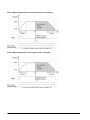
There are two kinds of control method, which are type 0 and type 1. Using the type 0 disable the setting
of the target value, and using the type 1 enables the setting. When using the type 1, even if the trigger
(execution condition) is on, the deceleration stop will be performed according to the target value.
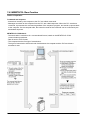
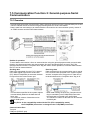
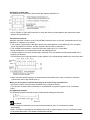
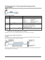
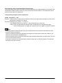
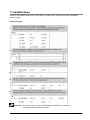
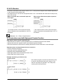
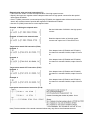
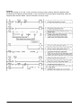
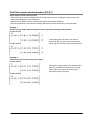
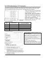
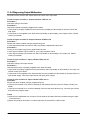
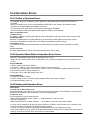
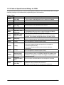
When the trigger (R1) is on, pulses are output from Y0 at an
initial speed of 1000 Hz, a target speed of 7000 Hz and an
acceleration time of 300 ms.
If the trigger (R1) is off, the deceleration stop will be
performed with a deceleration time of 450 ms. However, if
the trigger is turned on again, it will accelerate to the target
speed again.
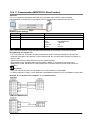
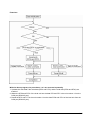
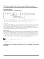
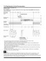
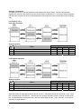
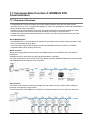
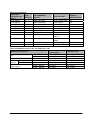
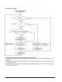
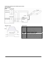
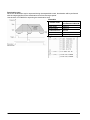
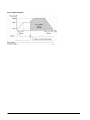
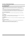
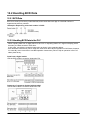
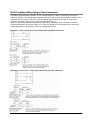
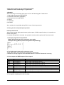
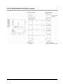
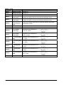
When this program ie executed, the positioning table and the
pulse output diagram will be as shown below.
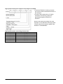
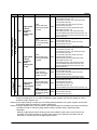
Positioning data table
DT0
Control code *1
DT2
DT4
DT6
DT8
DT10
Initial speed *2
Target speed *2
Acceleration time *3
Deceleration time *3
Target value *4
JOG operation type 0
Forward CW/CCW
1000 Hz
7000 Hz
300 ms
450 ms
0 pulse
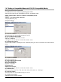
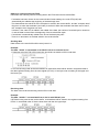
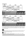
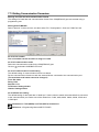
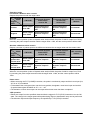
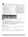
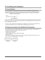
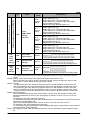
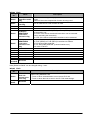
Note the following characteristics according to the
specified initial speed.
1. When the initial speed is 1 or higher, and lower than
46Hz, the control up to the maximum frequency to the
degree of 10kHz can be performed. If the frequency is
higher than that, the speed error will be larger.
2. When the initial speed is 46 or higher, and lower than
184Hz, the control up to 50kHz can be performed.
3. When the initial speed is 184 or higher, the control up to
50kHz can be performed. The speed error around 50kHz will
be smallest.
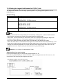
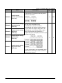
Change of speed during pulse output
1. If the target value is set to a value larger than 50kHz, it
will be corrected to 50kHz.
2. If the elapsed value crosses over the acceleration
forbidden area starting position during accelerating,
acceleration cannot be performed. For information on the
acceleration forbidden area starting position, check with the
special registers (from DT90400).
3. For deceleration, the speed cannot be lower than the
deceleration minimum speed. For information on the
deceleration minimum speed, check with the special
registers (from DT90400).
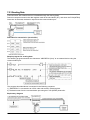
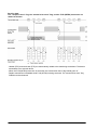
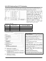
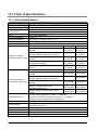
Explanation of pulse output operation
Pulses are output using a duty of 25% fixedly.
When outputting with the PULSE+SIGN method, pulses will
be output approx. 300µs later after the output of direction
signal. (The characteristics of a motor driver is considered.)
8-33