1
14
SLC 500™ Analog Output Modules
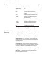
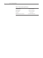
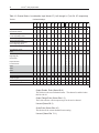
Channel update time will vary depending on mode of operation and
features implemented:
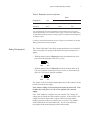
Table 7. Channel update time (all channels)
Mode
Class 1
Class 3
Your Module’s Response To
Slot Disabling
Update Time
5 ms
10 ms
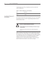
By writing to the status file in the modular SLC processor, you can disable
any chassis slot. Refer to your SLC programming manual for the slot
disable/enable procedure.
!
CAUTION—POSSIBLEEQUIPMENTOPERATION
Always understand the implications of disabling a module before using the
slot disable feature.
Failure to observe this precaution can cause unintended equipment
operation.
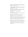
When you disable an output module’s slot, the module holds its outputs in
their last state in Class 1 mode. When you re-enable the output module’s
slot, the data that is in the processor image table is converted to an analog
output signal during the next scan. Slot disabling only affects enabled
channels. In Class 3 mode the output will go to its fault state, as
configured by the user, when the slot is disabled. See the “Set Output
Behavior Under Fault Condition” section in the next chapter.