1
Spacecraft Data Handling
IP Core User’s Manual
Based on GRLIB
Sandi Habinc
Copyright Gaisler Research, May 2008.
2
Table of contents
1
Introduction.............................................................................................................................. 6
1.1
1.2
1.3
2
AHB2PP - AMBA AHB to Packet Parallel Interface.............................................................. 8
2.1
2.2
2.3
2.4
2.5
2.6
2.7
2.8
2.9
3
Protocol ................................................................................................................................................. 25
Configuration options............................................................................................................................ 26
Signal descriptions ................................................................................................................................ 26
Library dependencies ............................................................................................................................ 27
Instantiation ........................................................................................................................................... 27
GRCTM - CCSDS Time Manager......................................................................................... 29
5.1
5.2
5.3
5.4
5.5
5.6
5.7
5.8
5.9
5.10
6
Overview ............................................................................................................................................... 13
Operation ............................................................................................................................................... 15
Operation ............................................................................................................................................... 17
Registers ................................................................................................................................................ 18
Vendor and device identifiers ................................................................................................................ 22
Configuration options............................................................................................................................ 23
Signal descriptions ................................................................................................................................ 23
Library dependencies ............................................................................................................................ 24
Instantiation ........................................................................................................................................... 24
GRCE/GRCD - Basic Convolutional Encoder and Quicklook Decoder ............................... 25
4.1
4.2
4.3
4.4
4.5
5
Overview ................................................................................................................................................. 8
Interrupts ................................................................................................................................................. 8
Registers .................................................................................................................................................. 9
AHB I/O area......................................................................................................................................... 10
Vendor and device identifiers ................................................................................................................ 11
Configuration options............................................................................................................................ 11
Signal descriptions ................................................................................................................................ 12
Library dependencies ............................................................................................................................ 12
Instantiation ........................................................................................................................................... 12
GRADCDAC - ADC / DAC Interface................................................................................... 13
3.1
3.2
3.3
3.4
3.5
3.6
3.7
3.8
3.9
4
Overview ................................................................................................................................................. 6
Implementation characteristics................................................................................................................ 6
Licensing ................................................................................................................................................. 6
Overview ............................................................................................................................................... 29
Data formats .......................................................................................................................................... 30
Operation ............................................................................................................................................... 32
Registers ................................................................................................................................................ 38
Vendor and device identifiers ................................................................................................................ 44
Configuration options............................................................................................................................ 45
Signal descriptions ................................................................................................................................ 46
Library dependencies ............................................................................................................................ 47
Instantiation ........................................................................................................................................... 47
Configuration tuning ............................................................................................................................. 48
GRFIFO - FIFO Interface ...................................................................................................... 52
6.1
6.2
6.3
6.4
Overview ............................................................................................................................................... 52
Interface................................................................................................................................................. 54
Waveforms............................................................................................................................................. 55
Transmission.......................................................................................................................................... 57
3
6.5
6.6
6.7
6.8
6.9
6.10
6.11
6.12
7
GRHCAN - CAN controller .................................................................................................. 74
7.1
7.2
7.3
7.4
7.5
7.6
7.7
7.8
7.9
7.10
7.11
7.12
7.13
7.14
7.15
8
Overview ............................................................................................................................................... 95
Registers ................................................................................................................................................ 96
Operation ............................................................................................................................................... 98
Vendor and device identifiers ................................................................................................................ 98
Configuration options............................................................................................................................ 99
Signal descriptions ................................................................................................................................ 99
Library dependencies ............................................................................................................................ 99
Instantiation ........................................................................................................................................... 99
GRPW - PacketWire Interface ............................................................................................. 100
9.1
9.2
9.3
9.4
9.5
9.6
10
Overview ............................................................................................................................................... 74
Interface................................................................................................................................................. 75
Protocol ................................................................................................................................................. 75
Status and monitoring............................................................................................................................ 76
Transmission.......................................................................................................................................... 76
Reception............................................................................................................................................... 79
Global reset and enable ......................................................................................................................... 82
Interrupt ................................................................................................................................................. 82
Registers ................................................................................................................................................ 83
Memory mapping .................................................................................................................................. 92
Vendor and device identifiers ................................................................................................................ 93
Configuration options............................................................................................................................ 93
Signal descriptions ................................................................................................................................ 93
Library dependencies ............................................................................................................................ 94
Instantiation ........................................................................................................................................... 94
GRPULSE - General Purpose Input Output .......................................................................... 95
8.1
8.2
8.3
8.4
8.5
8.6
8.7
8.8
9
Reception............................................................................................................................................... 59
Operation ............................................................................................................................................... 61
Registers ................................................................................................................................................ 63
Vendor and device identifiers ................................................................................................................ 71
Configuration options............................................................................................................................ 72
Signal descriptions ................................................................................................................................ 72
Library dependencies ............................................................................................................................ 73
Instantiation ........................................................................................................................................... 73
Operation ............................................................................................................................................. 100
Vendor and device identifiers .............................................................................................................. 103
Configuration options.......................................................................................................................... 103
Signal descriptions .............................................................................................................................. 104
Library dependencies .......................................................................................................................... 104
Instantiation ......................................................................................................................................... 105
PW2APB - PacketWire receiver to AMBA APB Interface ................................................. 106
10.1
10.2
10.3
10.4
10.5
10.6
10.7
10.8
Overview ............................................................................................................................................. 106
PacketWire interface............................................................................................................................ 106
Registers .............................................................................................................................................. 107
Vendor and device identifiers .............................................................................................................. 108
Configuration options.......................................................................................................................... 108
Signal descriptions .............................................................................................................................. 109
Library dependencies .......................................................................................................................... 109
Instantiation ......................................................................................................................................... 109
4
11
APB2PW - AMBA APB to PacketWire Transmitter Interface ........................................... 110
11.1
11.2
11.3
11.4
11.5
11.6
11.7
11.8
12
GRTM - CCSDS Telemetry Encoder................................................................................... 114
12.1
12.2
12.3
12.4
12.5
12.6
12.7
12.8
12.9
12.10
12.11
12.12
12.13
12.14
13
Overview ............................................................................................................................................. 114
References ........................................................................................................................................... 115
Layers .................................................................................................................................................. 116
Data Link Protocol Sub-Layer ............................................................................................................ 117
Synchronization and Channel Coding Sub-Layer ............................................................................... 119
Physical Layer ..................................................................................................................................... 122
Connectivity ........................................................................................................................................ 124
Operation ............................................................................................................................................. 125
Registers .............................................................................................................................................. 127
Vendor and device identifier................................................................................................................ 132
Configuration options.......................................................................................................................... 132
Signal descriptions .............................................................................................................................. 133
Library dependencies .......................................................................................................................... 133
Instantiation ......................................................................................................................................... 133
GRTC - Telecommand Decoder........................................................................................... 134
13.1
13.2
13.3
13.4
13.5
13.6
13.7
13.8
13.9
13.10
13.11
13.12
13.13
13.14
13.15
14
Overview ............................................................................................................................................. 110
PacketWire interface............................................................................................................................ 110
Registers .............................................................................................................................................. 111
Vendor and device identifiers .............................................................................................................. 112
Configuration options.......................................................................................................................... 112
Signal descriptions .............................................................................................................................. 113
Library dependencies .......................................................................................................................... 113
Instantiation ......................................................................................................................................... 113
Overview ............................................................................................................................................. 134
Data formats ........................................................................................................................................ 135
Coding Layer (CL) .............................................................................................................................. 136
Transmission........................................................................................................................................ 138
Relationship between buffers and FIFOs ............................................................................................ 143
Command Link Control Word interface (CLCW)............................................................................... 144
Configuration Interface (AMBA AHB slave) ..................................................................................... 145
Interrupts ............................................................................................................................................. 146
Miscellaneous...................................................................................................................................... 146
Registers .............................................................................................................................................. 147
Vendor and device identifiers .............................................................................................................. 154
Configuration options.......................................................................................................................... 155
Signal descriptions .............................................................................................................................. 156
Library dependencies .......................................................................................................................... 157
Instantiation ......................................................................................................................................... 157
GRTIMER - General Purpose Timer Unit ........................................................................... 158
14.1
14.2
14.3
14.4
14.5
14.6
14.7
14.8
Overview ............................................................................................................................................. 158
Operation ............................................................................................................................................. 158
Registers .............................................................................................................................................. 159
Vendor and device identifiers .............................................................................................................. 161
Configuration options.......................................................................................................................... 161
Signal descriptions .............................................................................................................................. 161
Library dependencies .......................................................................................................................... 162
Instantiation ......................................................................................................................................... 162
5
15
GRVERSION - Version and Revision information register................................................. 163
15.1
15.2
15.3
15.4
15.5
15.6
15.7
Overview ............................................................................................................................................. 163
Registers .............................................................................................................................................. 163
Vendor and device identifiers .............................................................................................................. 163
Configuration options.......................................................................................................................... 163
Signal descriptions .............................................................................................................................. 164
Library dependencies .......................................................................................................................... 164
Instantiation ......................................................................................................................................... 164
6
1
Introduction
1.1
Overview
The Spacecraft Data Handling IP cores represent a collection of cores that have been developed specifically for the space sector.
These IP cores implement functions commonly used in spacecraft data handling and management systems. They implement international standards from organizations such as Consultative Committee for
Space Data Systems (CCSDS), European Cooperation on Space Standardization (ECSS), and the
former Procedures, Standards and Specifications (PSS) from the European Space Agency (ESA).
The IP cores cover the following functions:
1.2
•
PacketWire Interface - acts as a master on the AMBA bus providing remote control
•
PacketWire Receiver Interface - acts as a slave on the AMBA bus
•
PacketWire Transmitter Interface - acts as a slave on the AMBA bus
•
Packet Parallel Interface - acts as a slave on the AMBA bus
•
Combined ADC / DAC Interface - supports devices targeted for the space sector
•
External FIFO Interface with DMA - supports devices targeted for the space sector
•
CAN controller with DMA, based on ESA’s HurriCANe IP core
•
CCSDS Time Manager - with datation and pulse generation
•
CCSDS/ECSS Convolutional Encoder and Quicklook Decoder
•
CCSDS/ECSS Telemetry Encoder
•
CCSDS/ECSS Telecommand Decoder - Coding Layer
•
CCSDS/ECSS Telemetry Receiver (for ground test station only)
•
CCSDS/ECSS Telecommand Transmitter (for ground test station only)
•
General Purpose Input Output - with pulse generation
•
General Purpose Timer Unit- with external clock input, event outputs, and datation latch
•
Version and Revision information register
Implementation characteristics
The cores are portable and can be implemented on most FPGA and ASIC technologies, and have been
tested for Actel RTAX and Xilinx Virtex-2 FPGA technologies.
The cores are available in VHDL source code and, when applicable, use the plug&play configuration
method described in the ‘GRLIB User’s Manual’.
1.3
Licensing
The tables below lists the provided IP cores and their AMBA plug&play device ID. The license column indicates if a core is available under GNU GPL and/or under a commercial license. Cores
marked with FT are only available in the FT version of GRLIB.
Note: The open-source version of GRLIB includes only cores marked with GPL or LGPL.
7
Table 1. Spacecraft data handling functions
Name
Function
Vendor:Device
License
GRTM
CCSDS Telemetry Encoder
0x01 : 0x030
FT *
GRTC
CCSDS Telecommand Decoder
0x01 : 0x031
FT *
GRPW
Packetwire receiver with AHB interface
0x01 : 0x032
COM/GPL
GRCTM
CCSDS Time manager
0x01 : 0x033
COM/GPL
GRHCAN
CAN controller with DMA
0x01 : 0x034
FT **
GRFIFO
External FIFO Interface with DMA
0x01 : 0x035
COM
GRADCDAC
Combined ADC / DAC Interface
0x01 : 0x036
COM
GRPULSE
General Purpose Input Output
0x01 : 0x037
FT
GRTIMER
General Purpose Timer Unit
0x01 : 0x038
FT
AHB2PP
Packet Parallel Interface
0x01 : 0x039
FT
GRVERSION
Version and Revision information register
0x01 : 0x03A
FT
APB2PW
PacketWire Transmitter Interface
0x01 : 0x03B
COM/GPL
PW2APB
PacketWire Receiver Interface
0x01 : 0x03C
COM/GPL
GRCE/GRCD
CCSDS/ECSS Convolutional Encoder and Quicklook Decoder
N/A
FT *
GRTMRX
CCSDS Telemetry Receiver
0x01 : 0x082
FT *
GRTCTX
CCSDS Telecommand Transmitter
0x01 : 0x083
FT *
Note *: The GRTM, GRTC, GRTMRX and GRTCTX core are not included in the FT delivery. Contact Gaisler Research for licensing details.
Note **: The delivery of the CAN controller does not contain the HurriCANe CAN Controller IP
core. The HurriCANe core must be obtained separately from the European Space Agency (ESA).
8
2
AHB2PP - AMBA AHB to Packet Parallel Interface
2.1
Overview
The AMBA AHB to Packet Parallel Interface implements the PacketParallel protocol used by the
Packet Telemetry Encoder (PTME) IP core and the Virtual Channel Assembler (VCA) device.
The core implements the following functions:
•
Packet Parallel protocol
•
General Purpose Input Output port
The core provides the following external and internal interfaces:
•
Packet Parallel interface (octet data, packet delimiter, write strobe, abort, ready, busy)
•
AMBA AHB slave interface, with sideband signals as per [GRLIB]
•
AMBA APB slave interface, with sideband signals as per [GRLIB]
The core incorporates status and monitoring functions accessible via the AMBA APB slave interface.
This includes:
•
Busy and ready signalling from Packet Parallel interface
•
Read back of output data
•
Interrupts on ready for new word, or ready for new packet
Data is transferred to the Packet Parallel interface by writing to the AMBA AHB slave interface,
located in the AHB I/O area. Writing is only possible when the Packet Parallel packet valid delimiter
is asserted, else the access results in an AMBA access error. It is possible to transfer one, two or four
bytes at a time, following the AMBA big-endian convention regarding send order. The last written
data can be read back via the AMBA AHB slave interface. Data are output as octets on the Packet Parallel interface.
In the case the data from a previous write access has not been fully transferred over the Packet Parallel
interface, a new write access will result in an AMBA retry response. The progress of the interface can
be monitored via the AMBA APB slave interface. An interrupt is generated when the data from the
last write access has been transferred. An interrupt is also generated when the Packet Parallel ready
indicator is asserted.
2.2
Interrupts
Two interrupts are implemented by the Packet Parallel interface:
Index:
Name:
Description:
0
NOT BUSY
Ready for a new data (word, half-word or byte)
1
READY
Ready for new packet
The interrupts are configured by means of the pirq VHDL generic.
9
2.3
Registers
The core is programmed through registers mapped into APB address space.
AHB2PP registers
Table 2.
APB address offset
Register
16#000#
Configuration Register
16#004#
Status Register
16#008#
Control Register
16#010#
Data Input Register
16#014#
Data Output Register
16#018#
Data Direction Register
2.3.1
Configuration Register (R/W)
Table 3. Configuration Register
31
3
-
WS
3-0:
WS
0
Number of additional Wait States
All bits are cleared to 0 at reset.
The width of the write strobe can be extended by mean of the WS field. The nominal asserted width is
one system clock period (corresponding to WS=0). The asserted period can be extended up to a total
asserted width of 16 system clock periods.
The minimum gap between octet write accesses when the strobe is de-asserted is one system clock
period when WS={0, 3}, two when WS={4, 7}, three when WS={8, 11}, and four when WS={12,
15}.
2.3.2
Status Register (R)
Table 4. Status register
31
3
2
BUSY
2:
1:
0:
1
PP Busy
0
PP Ready
BUSY
AHB2PP interface busy with data transfer
PP Busy Packet Parallel busy input
PP Ready Packet Parallel ready input
All bits are cleared to 0 at reset.
2.3.3
Control Register (R/W)
Table 5. Control Register
31
4
3
PP Abort
3:
2:
1:
0:
PP Abort
PP Valid
RESET
ENABLE
2
PP Valid
Packet Parallel abort output
Packet Parallel valid output
Reset complete core when 1
Enable Packet Parallel interface when 1, else enable GPIO function
1
0
RST
EN
10
All bits are cleared to 0 at reset. Note that RESET is read back as 0b.
2.3.4
Data Input Register (R)
Table 6. Data Input Register
31
8
7
0
DIN
7-0:
DIN
Input data
ppi.data[7:0]
All bits are cleared to 0 at reset.
2.3.5
Data Output Register (R/W)
Table 7. Data Output Register
31
8
7
0
DOUT
7-0:
DOUT
Output data
ppo.data[7:0]
All bits are cleared to 0 at reset.
Note that the GPIO functionality can only be used when the Packet Parallel interface is disabled via
the Control Register above.
2.3.6
Data Register (R/W)
Table 8. Data Direction Register
31
8
7
0
DDIR
7-0:
DDIR
Direction:
0b = input = high impedance,
1b = output = driven
ppo.enable[7:0]
All bits are cleared to 0 at reset.
Note that the GPIO functionality can only be used when the Packet Parallel interface is disabled via
the Control Register above.
2.4
AHB I/O area
Data to be transferred to the Packet Parallel interface is written to the AMBA AHB slave interface
which implements a AHB I/O area. See [GRLIB] for details.
Note that the address is not decoded by the core. Address decoding is only done by the AMBA AHB
controller, for which the I/O area location and size is configured by means of the ioaddr and iomask
VHDL generics.
11
It is possible to transfer one, two or four bytes at a time, following the AMBA big-endian convention
regarding send order. The last written data can be read back via the AMBA AHB slave interface. Data
are output as octets on the Packet Parallel interface.
Table 9. AHB I/O area - data word definition
31
24
DATA [31:24]
23
16
DATA [23:16]
15
8
7
DATA [15:8]
0
DATA [7:0]
Table 10. AHB I/O area - send order
Transfer size
Address
offset
DATA [31:24]
DATA [23:16]
DATA [15:8]
DATA [7:0] Comment
Word
0
first
second
third
last
Four bytes sent
Halfword
0
first
last
-
-
Two bytes sent
2
-
-
first
last
Two bytes sent
0
first
-
-
-
One byte sent
1
-
first
-
-
One byte sent
2
-
-
first
-
One byte sent
3
-
-
-
first
One byte sent
Byte
2.5
Vendor and device identifiers
The module has vendor identifier 0x01 (Gaisler Research) and device identifier 0x039. For description of vendor and device identifiers see GRLIB IP Library User’s Manual.
2.6
Configuration options
Table 11 shows the configuration options of the core (VHDL generics).
Table 11. Configuration options
Generic name
Function
Allowed range
Default
hindex
AHB master index.
1 - NAHBSLV-1
0
ioaddr
Addr field of the AHB IO bar.
0 - 16#FFF#
0
iomask
Mask field of the AHB IO bar.
0 - 16#FFF#
16#F00#
pindex
APB slave index
0 - NAPBSLV-1
0
paddr
Addr field of the APB bar.
0 - 16#FFF#
0
pmask
Mask field of the APB bar.
0 - 16#FFF#
16#FFC#
pirq
Interrupt line used by the AHB2PP.
0 - NAHBIRQ-1
0
syncrst
Only synchronous reset
0, 1
1
oepol
Output enable polarity
0, 1
1
12
2.7
Signal descriptions
Table 12 shows the interface signals of the core (VHDL ports).
Table 12. Signal descriptions
Signal name
Field
Type
Function
Active
RSTN
N/A
Input
Reset
Low
CLK
N/A
Input
Clock
-
APBI
*
Input
APB slave input signals
-
APBO
*
Output
APB slave output signals
-
AHBI
*
Input
AMB slave input signals
-
AHBO
*
Output
AHB slave output signals
-
PPI
busy_n
Input
Packet Parallel busy signal
-
ready
Packet Parallel ready signal
data[7:0]
PPO
abort
Packet Parallel data (GPIO only)
Output
Packet Parallel abort signal
-
valid_n
Packet Parallel packet delimiter signal
-
wr_n
Packet Parallel octet write strobe
data[7:0]
Packet Parallel octet data
enable[7:0]
Enable/drive octet data output
* see GRLIB IP Library User’s Manual
2.8
Library dependencies
Table 13 shows the libraries used when instantiating the core (VHDL libraries).
Table 13. Library dependencies
2.9
Library
Package
Imported unit(s)
Description
GRLIB
AMBA
Signals
AMBA signal definitions
TMTC
TMTC_Types
Signals, component
Component declarations, signals.
Instantiation
This example shows how the core can be instantiated.
TBD
13
3
GRADCDAC - ADC / DAC Interface
3.1
Overview
The block diagram shows a possible partitioning of the combined analogue-to-digital converter
(ADC) and digital-to-analogue converter (DAC) interface.
The combined analogue-to-digital converter (ADC) and digital-to-analogue converter (DAC) interface is assumed to operate in an AMBA bus system where an APB bus is present. The AMBA APB
bus is used for data access, control and status handling.
The ADC/DAC interface provides a combined signal interface to parallel ADC and DAC devices.
The two interfaces are merged both at the pin/pad level as well as at the interface towards the AMBA
bus. The interface supports simultaneously one ADC device and one DAC device in parallel.
Address and data signals unused by the ADC and the DAC can be used for general purpose input output, providing 0, 8, 16 or 24 channels.
The ADC interface supports 8 and 16 bit data widths. It provides chip select, read/convert and ready
signals. The timing is programmable. It also provides an 8-bit address output. The ADC conversion
can be initiated either via the AMBA interface or by internal or external triggers. An interrupt is generated when a conversion is completed.
The DAC interface supports 8 and 16 bit data widths. It provides a write strobe signal. The timing is
programmable. It also provides an 8-bit address output. The DAC conversion is initiated via the
AMBA interface. An interrupt is generated when a conversion is completed.
Figure 1. Block diagram of the GRADCDAC environment
3.1.1
Function
The core implements the following functions:
•
ADC interface conversion:
•
ready feed-back, or
•
timed open-loop
14
•
DAC interface conversion:
•
timed open-loop
•
General purpose input output:
•
unused data bus, and
•
unused address bus
•
Status and monitoring:
•
on-going conversion
•
completed conversion
•
timed-out conversion
Note that it is not possible to perform ADC and DAC conversions simultaneously. On only one conversion can be performed at a time.
3.1.2
Interfaces
The core provides the following external and internal interfaces:
•
Combined ADC/DAC interface
•
programmable timing
•
programmable signal polarity
•
programmable conversion modes
•
AMBA APB slave interface
The ADC interface is intended for amongst others the following devices:
Name:Width:Type:
AD574
12-bit
R/C*, CE, CS*, RDY*, tri-state
AD674
12-bit
R/C*, CE, CS*, RDY*, tri-state
AD774
12-bit
R/C*, CE, CS*, RDY*, tri-state
AD670
8-bit
R/W*, CE*, CS*, RDY, tri-state
AD571
10-bit
Blank/Convert*, RDY*, tri-state
AD1671
12-bit
Encode, RDY*, non-tri-state
LTC1414
14-bit
Convert*, RDY, non-tri-state
The DAC interface is intended for amongst others the following devices:
Name:
Width:
Type:
AD561
10-bit
Parallel-Data-in-Analogue-out
AD565
12-bit
Parallel-Data-in-Analogue-out
AD667
12-bit
Parallel-Data-in-Analogue-out, CS*
AD767
12-bit
Parallel-Data-in-Analogue-out, CS*
DAC08
8-bit
Parallel-Data-in-Analogue-out
15
3.2
Operation
3.2.1
Interfaces
The internal interface on the on-chip bus towards the core is a common AMBA APB slave for data
access, configuration and status monitoring, used by both the ADC interface and the DAC interface.
The ADC address output and the DAC address output signals are shared on the external interface.
The address signals are possible to use as general purpose input output channels. This is only realized
when the address signals are not used by either ADC or DAC.
The ADC data input and the DAC data output signals are shared on the external interface. The data
input and output signals are possible to use as general purpose input output channels. This is only
realized when the data signals are not used by either ADC or DAC.
Each general purpose input output channel shall be individually programmed as input or output. This
applies to both the address bus and the data bus. The default reset configuration for each general purpose input output channel is as input. The default reset value each general purpose input output channel is logical zero.
Note that protection toward spurious pulse commands during power up shall be mitigated as far as
possible by means of I/O cell selection from the target technology.
3.2.2
Analogue to digital conversion
The ADC interface supports 8 and 16 bit wide input data.
The ADC interface provides an 8-bit address output, shared with the DAC interface. Note
address timing is independent of the acquisition timing.
that
the
The ADC interface shall provide the following control signals:
•
Chip Select
•
Read/Convert
•
Ready
The timing of the control signals is made up of two phases:
•
Start Conversion
•
Read Result
The Start Conversion phase is initiated by one of the following sources, provided that no other conversion is ongoing:
•
Event on one of three separate trigger inputs
•
Write access to the AMBA APB slave interface
Note that the trigger inputs can be connected to internal or external sources to the ASIC incorporating
the core. Note that any of the trigger inputs can be connected to a timer to facilitate cyclic acquisition.
The selection of the trigger source is programmable. The trigger inputs is programmable in terms of:
Rising edge or Falling edge. Triggering events are ignored if ADC or DAC conversion is in progress.
The transition between the two phases is controlled by the Ready signal. The Ready input signal is
programmable in terms of: Rising edge or Falling edge. The Ready input signaling is protected by
means of a programmable time-out period, to assure that every conversion terminates. It is also possible to perform an ADC conversion without the use of the Ready signal, by means of a programmable
conversion time duration. This can be seen as an open-loop conversion.
The Chip Select output signal is programmable in terms of:
•
Polarity
•
Number of assertions during a conversion, either
16
•
Pulsed once during Start Conversion phase only,
•
Pulsed once during Start Conversion phase and once during Read Result phase, or
•
Asserted at the beginning of the Start Conversion phase and de-asserted at the end of the Read
Result phase
The duration of the asserted period is programmable, in terms of system clock periods, for the Chip
Select signal when pulsed in either of two phases.
The Read/Convert signal is de-asserted during the Start Conversion phase, and asserted during the
Read Result phase. The Read/Convert output signal is programmable in terms of: Polarity. The setup
timing from Read/Convert signal being asserted till the Chip Select signal is asserted is programmable, in terms of system clock periods. Note that the programming of Chip Select and Read/Convert
timing is implemented as a common parameter.
At the end of the Read Result phase, an interrupt is generated, indicating that data is ready for readout
via the AMBA APB slave interface. The status of an on-going conversion is possible to read out via
the AMBA APB slave interface. The result of a conversion is read out via the AMBA APB slave
interface. Note that this is independent of what trigger started the conversion.
An ADC conversion is non-interruptible. It is possible to perform at least 1000 conversions per second.
Start conversion
Read result
WS WS
WS WS
Clk
CS
RC
Trig
Rdy
Data
Addr
Settings:
RCPOL=0
CSPOL=0
RDYPOL=1
TRIGPOL=1
RDYMODE=1
CSMODE=00
ADCWS=0
Sample data
Figure 2. Analogue to digital conversion waveform, 0 wait states (WS)
17
3.2.3
Digital to analogue conversion
The DAC interface supports 8 and 16 bit wide output data. The data output signal is driven during the
conversion and is placed in high impedance state after the conversion.
The DAC interface provides an 8-bit address output, shared with the ADC interface. Note that the
address timing is independent of the acquisition timing.
The DAC interface provides the following control signal: Write Strobe. Note that the Write Strobe
signal can also be used as a chip select signal. The Write Strobe output signal is programmable in
terms of: Polarity. The Write Strobe signal is asserted during the conversion. The duration of the
asserted period of the Write Strobe is programmable in terms of system clock periods.
At the end the conversion, an interrupt is generated. The status of an on-going conversion is possible
to read out via the AMBA APB slave interface. A DAC conversion is non-interruptible.
Conversion
WS WS WS
Clk
WR
Data
Addr
Settings:
WRPOL=0
DACWS=0
Figure 3. Digital to analogue conversion waveform, 0 wait states (WS)
3.3
Operation
3.3.1
Interrupt
Two interrupts are implemented by the ADC/DAC interface:
Index:
Name:
Description:
0
ADC
ADC conversion ready
1
DAC
DAC conversion ready
The interrupts are configured by means of the pirq VHDL generic.
3.3.2
Reset
After a reset the values of the output signals are as follows:
Signal:
Value after reset:
ADO.Aout[7:0]
de-asserted
ADO.Aen[7:0]
de-asserted
ADO.Dout[15:0]
de-asserted
18
ADO.Den[15:0]
de-asserted
ADO.WR
de-asserted (logical one)
ADO.CS
de-asserted (logical one)
ADO.RC
de-asserted (logical one)
3.3.3
Asynchronous interfaces
The following input signals are synchronized to Clk:
3.4
•
ADI.Ain[7:0]
•
ADI.Din[15:0]
•
ADI.RDY
•
ADI.TRIG[2:0]
Registers
The core is programmed through registers mapped into APB address space.
Table 14. GRADCDAC registers
APB address offset
Register
16#000#
Configuration Register
16#004#
Status Register
16#010#
ADC Data Input Register
16#014#
DAC Data Output Register
16#020#
Address Input Register
16#024#
Address Output Register
16#028#
Address Direction Register
16#030#
Data Input Register
16#034#
Data Output Register
16#038#
Data Direction Register
3.4.1
Configuration Register [ADCONF] R/W
Table 15. Configuration register
31
30
29
28
27
26
25
24
23
22
21
20
19
DACWS
15
14
13
ADCWS
23-19:
18:
17-16:
DACWS
WRPOL
12
11
10
9
8
RCP CSMODE
OL
18
7
6
5
4
3
CSP
OL
RD
YM
OD
E
RD
YP
OL
TRI
GP
OL
TRIGMODE
Number of DAC wait states, 0 to 31 [5 bits]
Polarity of DAC write strobe:
0b = active low
1b = active high
DACDW DAC data width
00b = none
01b = 8 bit
ADO.Dout[7:0]
10b = 16 bit ADO.Dout[15:0]
11b = none/spare
17
16
WR DACDW
POL
2
1
0
ADCDW
19
15-11:
10:
9-8:
7:
6:
5:
4:
3-2:
1-0:
ADCWS
RCPOL
Number of ADC wait states, 0 to 31 [5 bits]
Polarity of ADC read convert:
0b = active low read
1b = active high read
CSMODE Mode of ADC chip select:
00b = asserted during conversion and read phases
01b = asserted during conversion phase
10b = asserted during read phase
11b = asserted continuously during both phases
CSPOL
Polarity of ADC chip select:0b = active low
1b = active high
RDYMODE:Mode of ADC ready:
0b = unused, i.e. open-loop
1b = used, with time-out
RDYPOL Polarity of ADC ready:
0b = falling edge
1b = rising edge
TRIGPOL Polarity of ADC triggers:
0b = falling edge
1b = rising edge
TRIGMODEADC trigger source:
00b = none
01b = ADI.TRIG[0]
10b = ADI.TRIG[1]
11b = ADI.TRIG[2]
ADCDW ADC data width:
00b = none
01b = 8 bit
ADI.Din[7:0]
10b = 16 bit ADI.Din[15:0]
11b = none/spare
The ADCDW field defines what part of ADI.Din[15:0] is read by the ADC.
The DACDW field defines what part of ADO.Dout[15:0] is written by the DAC.
Parts of the data input/output signals used neither by ADC nor by DAC are available for the general
purpose input output functionality.
Note that an ADC conversion can be initiated by means of a write access via the AMBA APB slave
interface, thus not requiring an explicit ADC trigger source setting.
The ADCONF.ADCWS field defines the number of system clock periods, ranging from 1 to 32, for
the following timing relationships between the ADC control signals:
•
ADO.RC stable before ADO.CS period
•
ADO.CS asserted period, when pulsed
•
ADO.TRIG[2:0] event until ADO.CS asserted period
•
Time-out period for ADO.RDY: 2048 * (1+ADCONF.ADCWS)
•
Open-loop conversion timing: 512 * (1+ADCONF.ADCWS)
The ADCONF.DACWS field defines the number of system clock periods, ranging from 1 to 32, for
the following timing relationships between the DAC control signals:
•
ADO.Dout[15:0] stable before ADO.WR period
•
ADO.WR asserted period
20
•
ADO.Dout[15:0] stable after ADO.WR period
3.4.2
Status Register [ADSTAT] R
Table 16. Status register
31
30
29
28
27
26
25
24
23
22
21
20
19
18
17
16
15
14
13
12
11
10
9
8
7
6
5
4
3
2
1
0
DA
CN
O
DA
CR
DY
DA
CO
N
AD AD
CTO CN
O
AD
CR
DY
AD
CO
N
6:
5:
4:
3:
2:
1:
0:
DACNO
DACRDY
DACON
ADCTO
ADCNO
ADCRDY
ADCON
DAC conversion request rejected (due
DAC conversion completed
DAC conversion ongoing
ADC conversion timeout
ADC conversion request rejected (due
ADC conversion completed
ADC conversion ongoing
to ongoing DAC or ADC conversion)
to ongoing ADC or DAC conversion)
When the register is read, the following sticky bit fields are cleared:
•
DACNO, DACRDY,
•
ADCTO, ADCNO, and ADCRDY.
Note that the status bits can be used for monitoring the progress of a conversion or to ascertain that the
interface is free for usage.
3.4.3
ADC Data Input Register [ADIN] R/W
Table 17. ADC Data Input Register
31
16
15
0
ADCIN
15-0:
ADCIN
ADC input data
ADI.Din[15:0]
A write access to the register initiates an analogue to digital conversion, provided that no other ADC
or DAC conversion is ongoing (otherwise the request is rejected).
A read access that occurs before an ADC conversion has been completed returns the result from a previous conversion.
Note that any data can be written and that it cannot be read back, since not relevant to the initiation of
the conversion.
Note that only the part of ADI.Din[15:0] that is specified by means of bit ADCONF.ADCDW is used
by the ADC. The rest of the bits are read as zeros.
Note that only bits dwidth-1 to 0 are implemented.
3.4.4
DAC Data Output Register [ADOUT] R/W
Table 18. DAC Data Output Register
31
16
15
DACOUT
15-0:
DACOUT DAC output data
ADO.Dout[15:0]
0
21
A write access to the register initiates a digital to analogue conversion, provided that no other DAC or
ADC conversion is ongoing (otherwise the request is rejected).
Note that only the part of ADO.Dout[15:0] that is specified by means of ADCONF.DACDW is driven
by the DAC. The rest of the bits are not driven by the DAC during a conversion.
Note that only the part of ADO.Dout[15:0] which is specified by means of ADCONF.DACDW can be
read back, whilst the rest of the bits are read as zeros.
Note that only bits dwidth-1 to 0 are implemented.
3.4.5
Address Input Register [ADAIN] R
Table 19. Address Input Register
31
8
7
0
AIN
7-0:
AIN
Input address
ADI.Ain[7:0]
All bits are cleared to 0 at reset.
Note that only bits awidth-1 to 0 are implemented.
3.4.6
Address Output Register [ADAOUT] R/W
Table 20. Address Output Register
31
8
7
0
AOUT
7-0:
AOUT
Output address
ADO.Aout[7:0]
All bits are cleared to 0 at reset.
Note that only bits awidth-1 to 0 are implemented.
3.4.7
Address Direction Register [ADADIR] R/W
Table 21. Address Direction Register
31
8
7
0
ADIR
7-0:
ADIR
Direction:
0b = input = high impedance,
1b = output = driven
ADO.Aout[7:0]
All bits are cleared to 0 at reset.
Note that only bits awidth-1 to 0 are implemented.
3.4.8
Data Input Register [ADDIN] R
Table 22. Data Input Register
31
16
15
DIN
15-0:
DIN
Input data
ADI.Din[15:0]
0
22
All bits are cleared to 0 at reset.
Note that only the part of ADI.Din[15:0] not used by the ADC can be used as general purpose input
output, see ADCONF.ADCDW.
Note that only bits dwidth-1 to 0 are implemented.
3.4.9
Data Output Register [ADDOUT] R/W
Table 23. Data Output Register
31
16
15
0
DOUT
15-0:
DOUT
Output data
ADO.Dout[15:0]
All bits are cleared to 0 at reset.
Note that only the part of ADO.Dout[15:0] neither used by the DAC nor the ADC can be used as general purpose input output, see ADCONF.DACDW and ADCONF. ADCDW.
Note that only bits dwidth-1 to 0 are implemented.
3.4.10 Data Register [ADDDIR] R/W
Table 24. Data Direction Register
31
16
15
0
DDIR
15-0:
DDIR
Direction:
0b = input = high impedance,
1b = output = driven
ADO.Dout[15:0]
All bits are cleared to 0 at reset.
Note that only the part of ADO.Dout[15:0] not used by the DAC can be used as general purpose input
output, see ADCONF.DACDW.
Note that only bits dwidth-1 to 0 are implemented.
3.5
Vendor and device identifiers
The module has vendor identifier 0x01 (Gaisler Research) and device identifier 0x036. For description of vendor and device identifiers see GRLIB IP Library User’s Manual.
23
3.6
Configuration options
Table 25 shows the configuration options of the core (VHDL generics).
Table 25. Configuration options
3.7
Generic
Function
Allowed range
Default
pindex
APB slave index
0 - NAPBSLV-1
0
paddr
Addr field of the APB bar.
0 - 16#FFF#
0
pmask
Mask field of the APB bar.
0 - 16#FFF#
16#FFF#
pirq
Interrupt line used by the GRADCDAC.
0 - NAHBIRQ-1
1
nchannel
Number of input/outputs
1 - 32
24
npulse
Number of pulses
1 - 32
8
invertpulse
Invert pulse output when set
1 - 32
0
cntrwidth
Pulse counter width
4 to 32
20
oepol
Output enable polarity
0, 1
1
Signal descriptions
Table 26 shows the interface signals of the core (VHDL ports).
Table 26. Signal descriptions
Signal name
Field
Type
Function
Active
RSTN
N/A
Input
Reset
Low
CLK
N/A
Input
Clock
-
APBI
*
Input
APB slave input signals
-
APBO
*
Output
APB slave output signals
-
ADI
ADI.Ain[7:0]
Input
Common Address input
-
ADI.Din[15:0]
ADC Data input
ADI.RDY
ADC Ready input
ADI.TRIG[2:0]
ADO
ADO.Aout[7:0]
ADC Trigger inputs
Output
Common Address output
ADO.Aen[7:0]
Common Address output enable
ADO.Dout[15:0]
DAC Data output
ADO.Den[15:0]
DAC Data output enable
ADO.WRDAC
Write Strobe
ADO.CSADC
Chip Select
ADO.RCADC
Read/Convert
-
* see GRLIB IP Library User’s Manual
Note that the VHDL generic oepol is used for configuring the logical level of ADO.Den and ADO.Aen while asserted.
24
3.8
Library dependencies
Table 27 shows the libraries used when instantiating the core (VHDL libraries).
Table 27. Library dependencies
3.9
Library
Package
Imported unit(s)
Description
GRLIB
AMBA
Signals
AMBA signal definitions
GAISLER
MISC
Signals
GRADCDAC component declaration
Instantiation
This example shows how the core can be instantiated.
TBD
25
4
GRCE/GRCD - Basic Convolutional Encoder and Quicklook Decoder
The Basic Convolutional Encoder (GRCE) comprises a synchronous bit serial input and a synchronous bit serial output. The output frequency is twice the input frequency.
The Basic Convolutional Quicklook Decoder (GRCD) comprises a synchronous bit serial input and a
synchronous bit serial output. The input frequency is twice the output frequency. The quicklook
decoder decodes the incoming bit stream without correcting for bit errors.
The GRCE / GRCD models are based on the Basic Convolutional Code specified by Consultative
Committee for Space Data Systems (CCSDS) and European Cooperation for Space Standardization
(ECSS).
[CCSDS] Telemetry Channel Coding, CCSDS 101.0-B-6, Issue 6, October 2002
4.1
[PSS]
Telemetry Channel Coding Standard, ESA PSS-04-103, Issue 1, September 1989
[ECSS]
Space Engineering -Telemetry channel coding, ECSS-E-50-01
Protocol
The basic convolutional code is a rate 1/2, constraint-length 7 transparent code which is well suited
for channels with predominantly Gaussian noise:
Nomenclature:
Code rate:
Constraint length:
Connection vectors:
Symbol inversion:
Convolutional code
1/2 bit per symbol.
7 bits.
G1 = 1111001 (171 octal);
G2 = 1011011 (133 octal).
On output path of G2.
26
4.2
Configuration options
Table 28 shows the configuration options of the cores (VHDL generics).
Table 28. Configuration options
4.3
Generic name
Function
Allowed range
Default
syncreset
Synchronous reset when set, else asynchronous
0-1
0
Signal descriptions
Table 30 shows the interface signals of the Basic Convolutional Encoder (GRCE) core (VHDL ports).
Table 29. Signal descriptions - GRCE
Signal name
Field
Type
Function
Active
Rst_N
N/A
Input
This active low input port synchronously resets
the model. The port is assumed to be deasserted
synchronously with the Cout system clock.
Low
Cin
N/A
Input
This input port is the bit clock for the data input
Din. The port is sampled on the rising Cout
edge. When Cin is sampled as asserted, a new bit
is present on the Din port.
High
Cin is assumed to have been generated from the
rising Cout edge, normally with a delay, and Din
is assumed to be stable after the falling Cin edge.
Din
N/A
Input
This input port is the serial data input for the
interface. Data are sampled on the rising Cout
edge when the Cin input is asserted. Input data
Din is thus qualified by the input bit clock Cin.
For each input data bit on Din, two bits are output on Dout.
-
Cout
N/A
Output
This input port is the system clock for the model.
All registers are clocked on the rising Cout edge.
The port also acts as the bit clock for the data
output Dout.
Rising
Dout
N/A
Output
This output port is the serial data output for the
interface. The output is clocked out on the rising
Cout edge.
-
27
Table 30 shows the interface signals of the GRCD core (VHDL ports).
Table 30. Signal descriptions - GRCD
4.4
Signal name
Field
Type
Function
Active
Rst_N
N/A
Input
This active low input port synchronously resets
the model. The port is assumed to be deasserted
synchronously with the Cin system clock.
Low
Cin
N/A
Input
This input port is the system clock for the model.
All registers are clocked on the falling Cin edge.
The port also acts as the bit clock for the data
input Din.
Falling
Din
N/A
Input
This input port is the serial data input for the
interface. Data are sampled on the falling Cin
edge. For two input data bits on Din, one bit is
output on Dout.
-
Cout
N/A
Output
This output port is the output bit clock. The output is clocked out on the falling Cin edge.
-
Dout
N/A
Output
This output port is the serial data output for the
interface. The output is clocked out on the falling
Cin edge. Dout is assumed to be sampled externally on the falling Cout edge.
-
Dlock
N/A
Output
This output port is asserted when the quick look
decoder is in lock and producing decoded data.
The output is clocked out on the falling Cin
edge.
High
Library dependencies
Table 31 shows the libraries used when instantiating the cores (VHDL libraries).
Table 31. Library dependencies
4.5
Library
Package
Imported unit(s)
Description
TMTC
TMTC_Types
Component
Component declaration
Instantiation
The GRCE/ GRCD cores are fully synchronous designs based on a single clock strategy. All registers
in the cores are reset synchronously or asynchronously, controlled by the syncrst VHDL generic. The
reset input requires external synchronisation to avoid any setup and hold time violations.
This example shows how the cores can be instantiated.
library
use
library
IEEE;
IEEE.Std_Logic_1164.all;
TMTC;
...
component GRCE
port(
Rst_n:
in
Cin:
in
Din:
in
Cout:
in
Dout:
out
end component GRCE;
component GRCD
Std_ULogic; -Std_ULogic; -Std_ULogic; -Std_ULogic; -Std_ULogic);--
Synchronous reset
Input data clock
Input data
Output data clock
Output data
28
port(
Rst_N:
in
Cin:
in
Din:
in
Cout:
out
Dout:
out
Dlock:
out
end component GRCD;
Std_ULogic; -Std_ULogic; -Std_ULogic; -Std_ULogic; -Std_ULogic; -Std_ULogic);--
Synchronous reset
Input data clock
Input data
Output data clock
Output data
Output locked
29
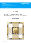
5
GRCTM - CCSDS Time Manager
5.1
Overview
The CCSDS Time Manager (GRCTM) provides basic time keeping functions such an Elapsed Time
(ET) counter according to the Consultative Committee for Space Data Systems (CCSDS) Unsegmented Code specification, [CCSDS]. It comprises a Frequency Synthesizer (FS) by which a binary
frequency is generated to drive the ET counter. The GRCTM provides support for setting the increment rate of the ET counter as well as of the FS counter.
The GRCTM provides datation services that sample the ET counter value on external events. It also
provides generation of periodic pulses with cycle periods of less than one second. All services in the
GRCTM core are accessible via an AMBA AHB slave interface.
The GRCTM provides a service for sampling the ET counter value on the occurrence of the time
strobe generated by the Packet Telemetry Encoder (PTME), generating a Standard Spacecraft Time
Source Packet according to the ESA Packet Telemetry Standard, [PSS]. The Time Source Packet can
be read out via the AMBA AHB slave interface and is transmitted directly to a telemetry encoder via
a serial interface.
The GRCTM can act as a master and/or a slave in a time distribution system. As a master only, the
GRCTM distributes the ET to GRCTM slaves via a TimeWire (TW) interface. As a slave only, the
GRCTM receives the ET via the TimeWire interface. When acting as a master and slave, the GRCTM
receives the ET from a master GRCTM, but can also distribute the ET to other slaves.
HCLK
CTM
HRESETn
ET & FS
IRESETn
Services
AHB Slave
interface
GRCTM
GRCTM
Datation[0:2]
Datation
TWSlave
Rs232Rx
Pulses[0:7]
Pulses
TWMaster
Rs232Tx
AHBIn
AHBOut
AHB Slave
TimePkt
Rs232Tx
TWSlave
TimeWire
interface
TWMaster
TimeMode[0:3]
TimePkt
TimeBusy_N
TimeStrobe
Time Packe
interface
Figure 4. Block diagram
5.1.1
Foreseen usage of the core
On-board time maintenance and distribution is to be handled through a master CCSDS Time Manager
(GRCTM) and one or more slave GRCTMs. Using a dedicated synchronisation line (TimeWire), the
slave time manager can be synchronised with the master GRCTM. The slave GRCTM can further distribute the time to the payload. The GRCTM slaves will thus be slaved to the master GRCTM, but
also act as masters for other modules. This isolates the master GRCTM from the payloads. The slave
GRCTM provides four datation register into which the Elapsed Time (ET) counter can be latched on
the occurrence of an external triggering event.
It is not possible to synchronise or set the ET counter in the master GRCTM. The ET counter can only
be cleared by means of hardware or software reset.
30
5.1.2
Description of a general system using the core
The general approach to accurately maintaining on-board time is to have a central time reference measuring the elapsed time from an arbitrary epoch and to distribute regularly this time information to onboard applications by means of messages and synchronisation pulses. Another approach would be to
have a centralised time system, where each application that needs to time stamp data could request the
unit maintaining the central time reference to provide the relevant time information. Such an approach
would have several inherent drawbacks, e.g. in systems with many users, the accuracy of a time stamp
could be jeopardised due to long service latency and excessive bus traffic could degrade the overall
performance of the data handling system.
The purpose of the GRCTM is to provide a building block for such time distribution services by providing the means for CCSDS compliant time keeping and a set of basic user time services. Most time
distribution implementations have required support from the application processor to maintain synchronisation between the central and the local time references. Protocols and formats for distributing
time information have differed between spacecraft and have sometimes only provided low resolution
or poor accuracy. The purpose of the GRCTM is to provide an accurate time coherence throughout the
spacecraft.
The correlation between the central time reference and ground has already been foreseen by providing
a time strobe from the Packet Telemetry encoder (PTME) core. The time strobe has a deterministic
relationship to the bit structure of the telemetry frame. This makes it possible to establish the time
relation between the assertion of this time strobe on-board and the reception of the relevant frame on
ground, taking into account the down link propagation delay. Each GRCTM instance maintains its
own copy of the central elapsed time reference with which on-board applications can time stamp their
data. This unbroken chain of time relationships on-board, and between the spacecraft and ground, provides a solution to the problem of knowing when an event took place on-board in any given spacetime frame.
The GRCTM is foreseen to be used both as a central elapsed time reference in the spacecraft data
management system, as well as the local elapsed time reference in an instrument or other subsystem.
By using standardised AMBA interfaces, the integration of the GRCTM should be simple for most
systems.
5.1.3
Functions not included
The GRCTM does not support alarm services.
The GRCTM does not support setting of an arbitrary epoch time.
5.2
Data formats
All Elapsed Time (ET) information handled by GRCTM is compliant with the CCSDS Unsegmented
Code defined in [CCSDS] and repeated hereafter.
5.2.1
Reference documents
[CCSDS] Time Code Formats, CCSDS 301.0-B-3, January 2002, www.ccsds.org
[PSS]
5.2.2
Packet Telemetry Standard, ESA PSS-04-106, Issue 1, January 1988
CCSDS Unsegmented Code: Preamble Field (P-Field)
The time code preamble field (P-Field) may be either explicitly or implicitly conveyed. If it is implicitly conveyed (not present with T-Field), the code is not self-identified, and identification must be
31
obtained by other means. As presently defined, the explicit representation of the P-Field is limited to
one octet whose format is described hereafter.
Table 32. CCSDS Unsegmented Code P-Field definition
Bit
Value
Interpretation
0
0
1-3
“001”
1958 January 1 epoch (Level 1)
“010”
Agency-defined epoch (Level 2) 1
Extension flag
4-5
(number of octets of coarse time) - 1
6-7
(number of octets of fine time)
Time code identification
1
Detail bits for information on the code
1 For the Standard Spacecraft Time Source Packet defined in the ESA Packet Telemetry Standard, bits 1 to 3
must are set to 010b.
5.2.3
CCSDS Unsegmented Code: Time Field (T-Field)
For the unsegmented binary time codes described herein, the T-Field consists of a selected number of
contiguous time elements, each element being one octet in length. An element represents the state of 8
consecutive bits of a binary counter, cascaded with the adjacent counters, which rolls over at a modulo
of 256.
Table 33. CCSDS Unsegmented Code T-Field definition
CCSDS Unsegmented Code
Preamble
Time Field
Field
-
Coarse time
“0000”
2
27
24
2
2
23
2
16
2
Fine time
15
2
8
7
2
2
0
-1
2
2
-8
2-9
2-14
“00”
The basic time unit is the second. The T-Field consists of 28 bits of coarse time (seconds) and 14 bits
of fine time (sub seconds). The coarse time code elements are a count of the number of seconds
elapsed from the epoch. The 28 bits of coarse time results in a maximum ambiguity period of approximately 8 years. Arbitrary epochs may be accommodated as a Level 2 code. The 14 bits of fine code
elements result in a resolution of 2-14 second (about 62 microseconds). This code is not UTC-based
and leap second corrections do not apply according to CCSDS.
5.2.4
Waveforms
Start
bit
Data
Stop
bits
Start LSB
MSB Stop
Start LSB
MSB Stop Stop
Start
bit
Parity Stop
bits
Data
Start LSB
MSB
P
Stop
Start LSB
MSB
P
Stop Stop
Break
Start
Stop
Figure 5. Bit asynchronous protocol
32
Active
Inactive
Width
Period
Figure 6. Pulse generation waveform
5.3
Operation
The CCSDS Time Manager (GRCTM) synthesizable core can be configured for various purposes.
The different functions presented hereafter can be used to from a GRCTM to act as a master, slave, or
master and slave.
5.3.1
Elapsed Time (ET)
The local Elapsed Time (ET) counter is based on a default 28 bit coarse time field and a 14 bit fine
time field, complying to the CCSDS Unsegmented Code (CUC) T-Field. The width of the two time
fields is fixed. The counter implementing the ET is incremented on the system clock only when
enabled by the frequency synthesizer described below. The ET is incremented with a pre-calculated
increment value, which matches the synthesised frequency. The local ET is output in the CUC format,
P-Field and T-Field, to be used by an application embedding the GRCTM. The P-Field is static with
the Time Code Identifier is set to 010b.
5.3.2
Frequency Synthesizer (FS)
The binary frequency required to determine the ET counter increment is derived from the system
clock using a 32 bit frequency synthesizer. The frequency synthesizer is incremented with a pre-calculated increment value, which matches the available system clock frequency. The FS simply generates
a tick every time it wraps around, which makes the ET to step forward with the pre-calculated increment value. The output of the frequency synthesizer is used for enabling the increment of the local ET
as described above. The 32 bit wide FS causes a systematic drift of less than 1 second/day.
5.3.3
TimeWire Interface (TW)
The GRCTM provides two TimeWire (TW) interfaces, one for the master function and one for the
slave function. The TimeWire interface is used for distributing the Elapsed Time (ET) of a GRCTM
master to one or more GRCTM slaves. The information carried in the synchronisation message comprises the Elapsed Time Field, which is 4 bytes, and a synchronisation pulse which is sent as a
BREAK command. The synchronisation pulse is used for synchronising both the ET and the phase of
the Frequency Synthesiser (FS) and is done once every second.
The GRCTM slave automatically synchronizes its ET with that of the GRCTM master without requiring any user support. A GRCTM that acts both as a master and a slave will be slaved to another master
via a slave TimeWire interface, and will simultaneously distribute its own ET to other GRCTM
slaves. The GRCTM slave will continue to work undisturbed in case a GRCTM master has failed. It is
also possible to disable the synchronisation by means of a register further to avoid failure propagation.
The TimeWire interface provides means for synchronising a GRCTM slave from a GRCTM that acts
both as a master and a slave, which being synchronised in turn from another GRCTM master.
The message is sent just before the synchronisation instance. A BREAK command is sent just after
the message to indicate the synchronisation pulse. The instance of the synchronisation actually
depends on the reception of the BREAK command and the time it takes to generate an internal pulse
in the receiver on which the previously sent message is latched into the ET counter of the slave. The
33
baseline is to send the synchronisation message and pulse to coincide with the wrap around of the subsecond bits in the ET. However, the time at which the message is sent out from the master is configurable by means of a generic (based on the fine part of the ET). An additional generic is provided for
the fine tuning of the message start. On the slave side, a generic is provided to set the fine part of the
ET at which the synchronisation pulse will occur. It is thus possible to synchronise the two units at
any arbitrary point in time, provided it is done once a second.
To tolerate large skew and drift differences between the clocks driving the master and the slave
GRCTM, a staged approach has been taken for the distribution of the synchronisation message and
the synchronisation pulse. The first GRCTM master in a time chain synchronises its GRCTM slaves
before it is time for these to act as masters and in turn send their synchronisation messages and pulses
to their slaves. This is done to avoid that the first GRCTM master will synchronise the GRCTM slaves
in such a way that no synchronisation messages are being sent out from these GRCTM due to clock
drift. Since the synchronisation only occurs once a second, the first GRCTM master in a time chain
has one second of time available to synchronise its GRCTM slaves before they synchronise their
slaves in turn.
The TimeWire interface is based on a bit asynchronous interface (RS232/422) with the following
specification:
•
115200 baud
•
1 start bit, 8 bit data, 1 or 2 stop bits (configured by generics)
•
odd parity is generated in transmitter, but ignored in the receiver (configured by generics)
•
no handshake
•
message delimiting via BREAK command (13 bits when sent)
•
synchronisation via BREAK command (13 bits when sent)
Table 34. TimeWire transmission protocol
Byte Number
Elapsed Time Coarse
Register (ETCR)
First
CCSDS Unsegmented Code
Time Field
Coarse Part
“0000” & [27:24]
31
2
224
Second
[23:16]
223
216
Third
[15:8]
215
28
Fourth
[7:0]
27
20
Fifth
N/A
[RS232 Break Command ]
Comment
Used as synchronisation pattern
Note that it is not possible for the TimeWire to carry sub-second phase information due to the usage of
the above RS232/422 type of interface.
5.3.4
Datation
The GRCTM comprises three datation registers for the purpose of datation of user events relative the
ET counter. The datation is triggered by three external edge sensitive inputs (programmable rising or
falling edge).
A fourth datation register is provided for sampling the ET counter when generating a Standard Spacecraft Time Source Packet as described below.
Each of the three general datation services is automatically disabled after an occurrence and is not reenabled until the corresponding fine time register is read. The format of all four datation registers is
compliant to the CUC T-Field.
The ET counter can be accessed directly via the AMBA AHB interface. This can be used for direct
datation from software.
34
5.3.5
Interrupts
The GRCTM provides individual interrupt lines for the incoming datation inputs, the time strobe
input and the occurrence of the individual pulse outputs. The interrupt lines are asserted for at least
two system clock cycles and can be connected to an external interrupt controller. The interrupts indicate that a new datation value can be read. The interrupts defined in table 35 are generated.
Table 35. Interrupts
Interrupt offset
Interrupt name
Description
1:st
DRL0
Datation Register 0 Latched
2:nd
DRL1
Datation Register 1 Latched
3:rd
DRL2
Datation Register 2 Latched
4:th
STL
Spacecraft Time Register Latched
5:th
PULSE0
Pulse 0 interrupt
6:th
PULSE1
Pulse 1 interrupt
7:th
PULSE2
Pulse 2 interrupt
8:th
PULSE3
Pulse 3 interrupt
9:th
PULSE4
Pulse 4 interrupt
10:th
PULSE5
Pulse 5 interrupt
11:th
PULSE6
Pulse 6 interrupt
12:th
PULSE7
Pulse 7 interrupt
5.3.6
Pulses
The GRCTM provides eight external outputs used for clock pulse distribution. The timing of each
pulse output is individually derived from the Elapsed Time counter. It is possible to program for each
pulse output individually the following parameters:
•
periodicity pulse
•
width of pulse
•
polarity of pulse
•
enable/disable pulse generation (reset status is disabled)
The pulse has two parts, the active and the inactive part. The active part always starts the pulse, followed by the inactive part. The polarity or logical level of the active part is programmable. The inactive part takes the logical inversion of the active pulse, and is the default output from the generator
when the pulse is not issued or the overall generation is disabled. The leading edge of the active pulse
part is aligned with the 1 second transition of the Elapsed Time counter.
The periodicity of the pulse corresponds to one of the ET bits that can be selected in the range 27 to 28 seconds, providing a range from 128 seconds to 3,91 ms, i.e. 0,0078 to 256 Hz frequency. See register definition for details.
The width of the active part of the pulse corresponds to one of the ET bits that can be selected in the
range 26 to 2-9 seconds, providing a range from 64 seconds to 1,95 ms. See register definition for
details.
It is possible to generate a pulse that has a duty cycle of 50%. It is also possible to generate a pulse for
which the active part is as short as 2-9 seconds, and its period is as high as 27 seconds. The effective
duty cycle can be as low as 2-9/27 for the longest period, up to 50% for the shortest period of 2-8 seconds = 256 Hz. The duty cycle choice becomes more restricted as the frequency increases. Note that it
is only possible to reduce the duty cycle in one direction: 50%/50%, 25%/75% ... 1%/99%. The active
part of the pulse can thus never be more than 50% of the cycle. It should be noted that the active pulse
width must be at most 50% of the pulse period. This is a requirement on the software usage.
35
The pulse outputs are guaranteed to be spike free. If the re-synchronisation of the GRCTM in slave
mode occurs within 0,5 ms of the expected synchronisation instance, the ongoing pulse output width
will be accurate to within 0,5 ms. Else, the pulse output will remain unchanged corresponding to up to
four times the expected output width.
If a pulse output is disabled by means of writing to the corresponding register (PDRx) (i.e. writing a
zero to the Pulse Enable bit (PE)), the pulse output will be immediately driven to the inversion of the
Pulse Level bit (PL), which corresponds to the level of the inactive part of the pulse. It is thus possible
to modify immediately the pulse output by disabling it using the PE bit and then changing the PL bit,
since the output will always drive the inversion of the PL bit while disabled.
5.3.7
Standard Spacecraft Time Source Packet
As mentioned above, the GRCTM comprises one datation register for sampling the ET counter when
generating a Standard Spacecraft Time Source Packet according to the ESA Packet Telemetry Standard, AD2, according to the following bit asynchronous protocol specification:
•
115200 baud
•
1 start bit, 8 bit data, 1 or 2 stop bits (configured by generics)
•
odd parity is generated (configured by generics)
•
no handshake
•
message delimiting via BREAK command (13 zero bits when sent)
The Spacecraft Time Coarse Register (STCR) and the Spacecraft Time Fine Register (STFR) are
available for readout of the datation time from the software. The software cannot block or initiate a
datation on these registers, since controlled from an external input pin. If multiple datation have
occurred since the registers were previously read, only the time at the first datation can be read from
the registers.
Table 36. Standard Spacecraft Time Source Packet
Octet number
Name
Value
0
Packet Header Octet 0
0x00
1
Packet Header Octet 1
0x00
2
Segment Flags & Sequence Count (0 to 5)
11b & 14 bit counter
3
Sequence Count (6 to 13)
4
Packet Length (0 to 7)
0x00
5
Packet Length (8 to 15)
0x00
6
Data Field & Sample Rate (0 to 3)
0000b & sampling rate
7
P-Field
0x2F
8
T-Field (231 to 224)
9
T-Field (223 to 216)
10
T-Field (215 to 28)
11
T-Field (27 to 20)
12
T-Field (2-1 to 2-8)
13
T-Field (2-9 to 2-16)
14
T-Field (2-17 to 2-24)
Always all zero
36
Table 37. Time sample rate
Bit
Rate (in frames)
Bit
Rate (in frames)
0000b
1
0101b
32
0001b
2
0110b
64
0010b
4
0111b
128
0011b
8
1000b
256
0100b
16
others
undefined
5.3.8
AMBA AHB slave interface
All time services, including the Elapsed Time counter in the embedded GRCTM core, are clocked by
the AMBA AHB clock HCLK. All input signals are assumed to be synchronous with the AMBA
AHB interface clock HCLK. No input signal synchronisation is performed in the core. All outputs are
synchronous with the AMBA AHB interface clock.
The AMBA AHB slave interface supports 32 bit wide data input and output. Since each access is a
word access, the two least significant address bits are assumed always to be zero. Only address bits
23:0 are decoded. Note that address bits 31:24 are not decoded and should thus be handled by the
AHB arbiter/decoder. The address input of the AHB slave interfaces is thus incompletely decoded.
Misaligned addressing is not supported. One wait state is introduced for read and write accesses.
When the CCSDS field is narrower than the AMBA data width, zeros are padded to the right. Remapping between the opposing numbering conventions in the CCSDS and AMBA documentation is
performed automatically. For read accesses, unmapped bits are always driven to zero.
The interface provides direct access to the T-Field of the ET counter.
The AMBA AHB interface has been reduced in function to support only what is required for the
GRCTM. The following AMBA AHB features are constrained:
•
Only supports HSIZE=WORD, HRESP_ERROR generated otherwise
•
Only supports HMASTLOCK='0', HRESP_ERROR generated otherwise
•
Only supports HBURST=SINGLE and INCR, HRESP_ERROR generated otherwise
•
No HPROT decoding
•
No HSPLIT generated
•
No HRETRY generated
•
HRESP_ERROR generated for unmapped addresses, and for write accesses to register without
any writeable bits
•
Only big-endianness is supported.
•
Frequency synthesis and time increment configuration
The increment values for the ET and FS counters depend on the implemented width of each counter
and the frequency of the available on the system clock.
5.3.9
Miscellaneous
The accuracy of the transmission or reception baud rate of the bit asynchronous serial interface is
dependent on the selected system frequency and baud rate. The number of system clock periods used
for sending or receiving a bit is directly proportional to the integer part of the division of the system
frequency with the baud rate.
The BREAK command received on the bit asynchronous serial interface is a sequence of logical zeros
that is at least one bit period longer than the normal byte frame, i.e. start bit, eight data bits, optional
parity, one or two stop bits. When transmitted, it is always 13 bits.
37
5.3.10 Numbering and naming conventions
Convention according to the CCSDS recommendations, applying to time structures:
•
The most significant bit of an array is located to the left, carrying index number zero.
•
An octet comprises eight bits.
Table 38. CCSDS n-bit field definition
CCSDS n-bit field
most significant
0
least significant
1 to n-2
n-1
Convention according to AMBA specification, applying to the APB/AHB interfaces:
•
Signal names are in upper case, except for the following:
•
A lower case 'n' in the name indicates that the signal is active low.
•
Constant names are in upper case.
•
The least significant bit of an array is located to the right, carrying index number zero.
•
Big-endian support.
Table 39. AMBA n-bit field definition
AMBA n-bit field
most significant
n-1
least significant
n-2 down to 1
General convention, applying to all other signals and interfaces:
•
Signal names are in mixed case.
•
An upper case '_N' suffix in the name indicates that the signal is active low.
0
38
5.4
Registers
The core is programmed through registers mapped into AHB I/O address space.
Table 40. GRCTM registers
AHB address offset
Register
0x00
Global Reset Register (GRR)
0x04
Global Control Register (GCR)
0x08
Global Status Register (GSR)
0x14
Preamble Field Register (PFR)
0x18
Elapsed Time Coarse Register (ETCR)
0x1C
Elapsed Time Fine Register (ETFR)
0x20
Datation Coarse Register 0 (DCR0)
0x24
Datation Fine Register 0 (DFR0)
0x28
Datation Coarse Register 1 (DCR1)
0x2C
Datation Fine Register 1 (DFR1)
0x30
Datation Coarse Register 2 (DCR2)
0x34
Datation Fine Register 2 (DFR2)
0x38
Spacecraft Time Datation Coarse Register (STCR)
0x3C
Spacecraft Time Datation Fine Register (STFR)
0x40
Pulse Definition Register 0
0x44
Pulse Definition Register 1
0x48
Pulse Definition Register 2
0x4C
Pulse Definition Register 3
0x50
Pulse Definition Register 4
0x54
Pulse Definition Register 5
0x58
Pulse Definition Register 6
0x5C
Pulse Definition Register 7
0x60
Pending Interrupt Masked Status Register
0x64
Pending Interrupt Masked Register
0x68
Pending Interrupt Status Register
0x6C
Pending Interrupt Register
0x70
Interrupt Mask Register
0x74
Pending Interrupt Clear Register
Table 41. Global Reset Register (GRR)
31
24 23
1
SEB
31: 24
23: 1
0
RESERVED
SEB (Security Byte):
Write:
‘0x55’= the write will have effect (the register will be updated).
Any other value= the write will have no effect on the register.
Read:
All zero.
RESERVED
Write:
Don’t care.
Read:
All zero.
System reset (SRST): [1]
Write:
‘1’= initiate reset,‘0’= do nothing
0
SRST
39
Read:
Table 41. Global Reset Register (GRR)
‘1’= unsuccessful reset, ‘0’= successful reset
Power-up default: 0x00000000
Table 42. Global Control Register (GCR)
31
24 23
SEB
31: 24
23: 13
13
RESERVED
10
9
8
DRE0
-
SYNC
7
0
RESERVED
Write:
‘0x55’= the write will have effect (the register will be updated).
Any other value= the write will have no effect on the register.
Read:
All zero.
RESERVED
Write:
Don’t care.
Read:
All zero.
Datation Register2 Edge (DRE2)
11
Datation Register1 Edge (DRE1)
10
Datation Register0 Edge (DRE0)
9
RESERVED
Write/Read:
Write/Read:
Write/Read:
7: 0
11
DRE1
SEB (Security Byte):
12
8
12
DRE2
‘0’= falling, ‘1’= rising
‘0’= falling, ‘1’= rising
‘0’= falling, ‘1’= rising
Write:
Don’t care.
Read:
All zero.
Synchronise slave (SYNC)
Write:
‘0’= disabled, ‘1’= enabled
Read:
‘0’= disabled, ‘1’= enabled
RESERVED
Write:
Don’t care.
Read:
All zero.
Power-up default: 0x00001C00
Table 43. Global Status Register (GSR) [8]
31
4
RESERVED
31: 4
3
2
1
0
RESERVED
Write:
Don’t care.
Read:
All zero.
Spacecraft Time Register Latched (STL): [3]
Write:
Don’t care.
Read:
‘1’ = Latched with new value, ‘0’ = old value
Datation Register 2 Latched (DRL2): [4]
Write:
Don’t care.
Read:
‘1’ = Latched with new value, ‘0’ = old value
Datation Register 1 Latched (DRL1): [4]
Write:
Don’t care.
Read:
‘1’ = Latched with new value, ‘0’ = old value
Datation Register 0 Latched (DRL0): [4]
Write:
Don’t care.
Read:
‘1’ = Latched with new value, ‘0’ = old value
Power-up default: 0x00000000
3
2
1
0
STL
DRL2
DRL1
DRL0
40
Table 44. Preamble Field Register (PFR) [8]
31
8
RESERVED
31: 8
7: 0
7
0
P-FIELD
RESERVED
Write:
Don’t care.
Read:
All zero.
Preamble Field (P-Field):
Write:
Don’t care.
Read:
Static P-Field
Power-up default: 0x0000002E
Table 45. Elapsed Time Coarse Register (ETCR) [8]
31
0
T-FIELD, COARSE
31: 0
T-Field, coarse part [5]
Write:
Don’t care.
Read:
T-Field, coarse part
Power-up default: 0x00000000
Table 46. Elapsed Time Fine Register (ETFR) [8]
31
16 15
0
T-FIELD, FINE
31: 16
15: 0
T-Field, fine part [5]
Write:
Don’t care.
Read:
T-Field, fine part
RESERVED
Write:
Don’t care.
Read:
All zero.
Power-up default: 0x00000000
Table 47. Datation Time Coarse Register 0 (DCR0) [8]
31
0
T-FIELD, COARSE
31: 0
T-Field, coarse part [6]
Write:
Don’t care.
Read:
T-Field, coarse part
Power-up default: 0x00000000
Table 48. Datation Time Fine Register 0 (DFR0) [8]
31
16 15
T-FIELD, FINE
31: 16
15: 0
T-Field, fine part [6]
Write:
Don’t care.
Read:
T-Field, fine part
RESERVED
Write:
Don’t care.
Read:
All zero.
Power-up default: 0x00000000
0
41
Table 49. Datation Time Coarse Register 1 (DCR1) [8]
31
0
T-FIELD, COARSE
31: 0
T-Field, coarse part [6]
Write:
Don’t care.
Read:
T-Field, coarse part
Power-up default: 0x00000000
Table 50. Datation Time Fine Register 1 (DFR1) [8]
31
16 15
0
T-FIELD, FINE
31: 16
15: 0
T-Field, fine part [6]
Write:
Don’t care.
Read:
T-Field, fine part
RESERVED
Write:
Don’t care.
Read:
All zero.
Power-up default: 0x00000000
Table 51. Datation Time Coarse Register 2 (DCR2) [8]
31
0
T-FIELD, COARSE
31: 0
T-Field, coarse part [6]
Write:
Don’t care.
Read:
T-Field, coarse part
Power-up default: 0x00000000
Table 52. Datation Time Fine Register 2 (DFR2) [8]
31
16 15
0
T-FIELD, FINE
31: 16
15: 0
T-Field, fine part [6]
Write:
Don’t care.
Read:
T-Field, fine part
RESERVED
Write:
Don’t care.
Read:
All zero.
Power-up default: 0x00000000
Table 53. Spacecraft Time Datation Coarse Register (STCR) [8]
31
0
T-FIELD, COARSE
31: 0
T-Field, coarse part [7]
Write:
Don’t care.
Read:
T-Field, coarse part
Power-up default: 0x00000000
42
Table 54. Spacecraft Time Datation Fine Register (STFR) [8]
31
16 15
0
T-FIELD, FINE
31: 16
15: 0
T-Field, fine part [7]
Write:
Don’t care.
Read:
T-Field, fine part
RESERVED
Write:
Don’t care.
Read:
All zero.
Power-up default: 0x00000000
Table 55. Pulse Definition Register 0 to 7 (PDR0 to PDR7)
31
24 23
RESERVED
31: 24
23: 20
20 19
PP
16 15
PW
11 10
RESERVED
9
2
PL
RESERVED
RESERVED
Write:
Don’t care.
Read:
All zero.
Pulse Period (PP):
Write/Read:
'0000'
=
2 7 seconds
'0001'
=
2 6 seconds
'0010'
=
2 5 seconds
'1110'
=
2 -7 seconds
'1111’
=
2 -8 seconds
Period
=
2 (7-PP)
Frequency
=
2 -(7-PP)
'0000'
=
2 6 seconds
'0001'
=
2 5 seconds
'0010'
=
2 4 seconds
'1110'
=
2 -8 seconds
'1111’
=
2 -9 seconds
Width
=
2 (6-PW)
...
19: 16
Pulse Width (PW):
Write/Read:
...
15: 11
10
RESERVED
Write:
Don’t care.
Read:
All zero.
Pulse Level (PL): Defines logical level of active part of pulse output.
Write/Read:
9: 2
‘0’= Low, ‘1’= High
RESERVED
Write:
Don’t care.
Read:
All zero.
1
Pulse Enable (PE):
0
RESERVED
Write/Read:
Write:
‘0’= disabled, ‘1’= enabled
Don’t care.
1
0
PE
-
43
Table 55. Pulse Definition Register 0 to 7 (PDR0 to PDR7)
Read:
All zero.
Power-up default: 0x00000400
Legend:
[1]
The global system reset caused by the SRST-bit in the GRR-register results in the following actions:
- Initiated by writing a ‘1”, gives ‘0’ on read-back when the reset was successful.
- No need to write a ‘0’ to remove the reset.
- Unconditionally, means no need to check/disable something in order for this reset-function to correctly execute.
- Could of course lead to data-corruption coming/going from/to the reset core.
Behaviour:
- Resets the complete core (all logic, buffers & register values)
(except for the ET and FS counters which continue running undisturbed)
- Behaviour is similar to a power-up.
- This reset shall not cause any spurious interrupts
{Note that the above actions require that the HRESET signal is fed back inverted to HRESETn}
[2]
The channel reset results in the following actions:
Not implemented in Global Configuration Register.
[3]
This bit is sticky which means that it remains asserted until the corresponding STFR register is read at which time the
bit is cleared. The corresponding registers should be read in the STCR – STFR order.
[4]
This bit is sticky which means that it remains asserted until the corresponding Defraud register is read at which point
the bit is cleared. The corresponding registers should be read in the DCRx – DFRx order.
[5]
When ETCR is read, the ETFR register is latched and are not released until ETFR has been read. The registers should
be read in the ETCR – ETFR order.
[6]
The coarse and fine time part of the register pair is latched on an external event and is released on reading the corresponding fine time register. No new event is accepted until the corresponding fine time register has been read.
[7]
The coarse and fine time part of the register pair is latched on an external event. No new event is accepted until the corresponding fine time register has been read. This does not prevent datations to occur and Standard Spacecraft Time
Source Packet to be generated.
[8]
An AMBA AHB ERROR response is generated if a write access is attempted to a register which does not have any
writeable bits.
5.4.1
Interrupt registers
The interrupt registers give complete freedom to the software, by providing means to mask interrupts,
clear interrupts, force interrupts and read interrupt status.
When an interrupt occurs the corresponding bit in the Pending Interrupt Register is set. The normal
sequence to initialize and handle a module interrupt is:
•
Set up the software interrupt-handler to accept an interrupt from the module.
•
Read the Pending Interrupt Register to clear any spurious interrupts.
•
Initialize the Interrupt Mask Register, unmasking each bit that should generate the module interrupt.
•
When an interrupt occurs, read the Pending Interrupt Status Register in the software interrupthandler to determine the causes of the interrupt.
•
Handle the interrupt, taking into account all causes of the interrupt.
•
Clear the handled interrupt using Pending Interrupt Clear Register.
Masking interrupts: After reset, all interrupt bits are masked, since the Interrupt Mask Register is zero.
To enable generation of a module interrupt for an interrupt bit, set the corresponding bit in the Interrupt Mask Register.
44
Clearing interrupts: All bits of the Pending Interrupt Register are cleared when it is read or when the
Pending Interrupt Masked Register is read. Reading the Pending Interrupt Masked Register yields the
contents of the Pending Interrupt Register masked with the contents of the Interrupt Mask Register.
Selected bits can be cleared by writing ones to the bits that shall be cleared to the Pending Interrupt
Clear Register.
Forcing interrupts: When the Pending Interrupt Register is written, the resulting value is the original
contents of the register logically OR-ed with the write data. This means that writing the register can
force (set) an interrupt bit, but never clear it.
Reading interrupt status: Reading the Pending Interrupt Status Register yields the same data as a read
of the Pending Interrupt Register, but without clearing the contents.
Reading interrupt status of unmasked bits: Reading the Pending Interrupt Masked Status Register
yields the contents of the Pending Interrupt Register masked with the contents of the Interrupt Mask
Register, but without clearing the contents.
The interrupt registers comprise the following:
•
Pending Interrupt Masked Status Register
[PIMSR]
R
•
Pending Interrupt Masked Register
[PIMR]
R
•
Pending Interrupt Status Register
[PISR]
R
•
Pending Interrupt Register
[PIR]
R/W
•
Interrupt Mask Register
[IMR]
R/W
•
Pending Interrupt Clear Register
[PICR]
W
Table 56. Interrupt registers
31
12
-
11
10:
9:
8:
7:
6:
5:
4:
3:
2:
1:
0:
11
PULSE7
PULSE7
PULSE6
PULSE5
PULSE4
PULSE3
PULSE2
PULSE1
PULSE0
STL
DRL2
DRL1
DRL0
...
4
3
2
1
0
PULSE0
STL
DRL2
DRL1
DRL0
Pulse 7 interrupt
Pulse 6 interrupt
Pulse 5 interrupt
Pulse 4 interrupt
Pulse 3 interrupt
Pulse 2 interrupt
Pulse 1 interrupt
Pulse 0 interrupt
Spacecraft Time Register Latched
Datation Register 2 Latched
Datation Register 1 Latched
Datation Register 0 Latched
All bits in all interrupt registers are reset to 0b after reset.
5.5
Vendor and device identifiers
The core has vendor identifier 0x01 (Gaisler Research) and device identifier 0x033. For description of
vendor and device identifiers see GRLIB IP Library User’s Manual.
45
5.6
Configuration options
Table 57 shows the configuration options of the core (VHDL generics).
Table 57. Configuration options
Generic
Function
Description
Allowed range Default
GRLIB AMBA plug&play settings
hindex
AHB slave index
hirq
AHB slave interrupt
singleirq
Single interrupt
ioaddr
Integer
0
Integer
0
Integer
0
IO area address
0 - 16#FFF#
0
iomask
IO area mask
0 - 16#FFF#
16#FFF#
syncrst
synchronous reset
0-1
0
gMaster
Master CTM support
0-1
0
gSlave
Slave CTM support
0-1
0
gDatation
Datation support
0-1
0
gPulse
Pulse support
0-1
0
gTimePacket
Time Packet support
0-1
0
Enable interrupt registers
Features settings
Frequency synthesizer and Elapsed Time counter settings
gFrequency
Frequency
Synthesizer
Defines the accuracy of the synthesized
reference time, the wider the synthesizer
the less drift is induced.
2 - 32
32
gETIncrement
Increment of
ET counter
Defines with what value the Elapsed Time
counter is to be incremented each time
when the Frequency Synthesizer wraps
around. The highest resolution is when the
value is set to 1. The ET increment needs
to match the synthesized frequency.
Integer
1
gFSIncrement
Increment of
FS counter
Defines the increment value of the Frequency Synthesizer which is added to the
counter every system clock cycle. It
defines the frequency of the synthesized
reference time. The synthesized frequency
needs to match the ET increment.
Integer
2111062
gTWStart
ETF at msg start
ET Fine at start of message [1]
Integer
16#FFDC00#
gTWAdjust
Adjust phase of msg
System clock based tuning of message start Integer
1636
gTWTransmit
ETF at transmission
ET Fine at synchronisation (master) [1]
Integer
16#000000#
gTWRecieve
ETF at reception
ET Fine at synchronisation (slave) [1] [2]
Integer
16#FFC000#
gDebug
Debug when set
Only used for TW settings adjustments.
0-1
0
TimeWire settings
Asynchronous bit serial interface settings (TimeWire and Time Packet)
gSystemClock
System frequency
System clock frequency [Hz]
Integer
33333333
gBaud
Baud rate
[Baud]
Integer
115200
gOddParity
Odd parity
Odd parity generated, but not checked
0-1
0
gTwoStopBits
Number of stop bits
0=one stop bit, 1=two stop bits
0-1
0
Legend:
[1]
These generics are defined as 24 bit ET fine time values, thus 16#FFFC00# corresponds to all the 14 implemented bits
being all-ones.
[2]
For proper mitigation of spikes on the Pulses[0:7] outputs, only the leftmost bits should be set.
46
5.7
Signal descriptions
Table 58 shows the interface signals of the core (VHDL ports).
Table 58. Signal descriptions
Signal name
Field
Type
Function
Description
Active
HRESETn
N/A
Input
Reset
Resets the ET & FS in the
VHDL core. The signal is
assumed synchronous with
rising HCLK edge.
Low
CRESETn
N/A
Input
Reset
Resets all logic but the ET
& FS in the VHDL core.
The signal is assumed synchronous with rising
HCLK edge.
Low
HCLK
N/A
Input
Clock
TWSLAVE
Input
CTMIN
CTMOUT
-
TimeWire slave
TimeWire input
-
DATATION
Datation input
The inputs are sampled on
rising HCLK edge.
-
TIMEMODE
Time rate select
Selects the rate of the time
strobe periodicity
-
TIMESTROBE
Time strobe input
-
TIMEBUSY_N
Time packet busy
Low
TWMASTER
Output
TimeWire master
TimeWire output
PULSES
Pulse outputs
The outputs are driven on
rising HCLK edge.
TIMEPKT
Time packet data
ELAPSEDTIME
Elapsed Time
ELAPSEDSYNC
Synchronisation
-
-
“0000” & ET coarse [27:0]
& ET fine [-1:-14] & “00”
-
AHBIN
*
Input
AMB slave input signals
-
AHBOUT
*
Output
AHB slave output signals
-
Interrupts
Location on
HIRQ bus
depends on
hirq generic.
If hirq=0, no
interrupt will
be generated.
HIRQ(hirq+11)
PULSES(7) output
HIRQ(hirq+10)
PULSES(6) output
HIRQ(hirq+9)
PULSES(5) output
HIRQ(hirq+8)
PULSES(4) output
HIRQ(hirq+7)
PULSES(3) output
HIRQ(hirq+6)
PULSES(2) output
HIRQ(hirq+5)
PULSES(1) output
HIRQ(hirq+4)
PULSES(0) output
HIRQ(hirq+3)
STL
HIRQ(hirq+2)
DRL2
HIRQ(hirq+1)
DRL1
HIRQ(hirq+0)
DRL0
* see GRLIB IP Library User’s Manual
If singleirq=1
only one
common
interrupt will
be generate
using hirq.
47
5.8
Library dependencies
Table 59 shows libraries used when instantiating the core (VHDL libraries).
Table 59. Library dependencies
5.9
Library
Package
Imported unit(s)
Description
GRLIB
AMBA
Signals
AMBA signal definitions
TMTC
TMTC_Types
Signals, component
Signals and component declaration
Instantiation
This example shows how the core can be instantiated.
library
use
library
use
library
use
IEEE;
IEEE.Std_Logic_1164.all;
GRLIB;
GRLIB.AMBA.all;
TMTC;
TMTC.TMTC_Types.all;
...
component GRCTM is
generic(
hindex:
in
hirq:
in
ioaddr:
in
iomask:
in
syncrst:
in
Integer
Integer
Integer
Integer
Integer
gMaster:
gSlave:
gDatation:
gPulse:
gTimePacket:
in
in
in
in
in
Natural
Natural
Natural
Natural
Natural
range
range
range
range
range
gFrequency:
gETIncrement:
gFSIncrement:
in
in
in
Positive
Natural := 1;
Natural := 2111062;
gTWStart:
gTWAdjust:
gTWTransmit:
gTWRecieve:
in
in
in
in
Natural
Natural
Natural
Natural
:=
:=
:=
:=
0
0
0
0
0
to
to
to
to
to
1
1
1
1
1
16#FFDC00#;
1636;
16#000000#;
16#FFC000#;
gSystemClock: in
Natural := 33333333;
gBaud:
in
Natural := 115200;
gOddParity:
in
Natural range 0 to 1
gTwoStopBits: in
Natural range 0 to 1
gDebug:
in
Natural range 0 to 1
port(
-- AMBA AHB system signals
HCLK:
in
Std_ULogic;
HRESETn:
in
Std_ULogic;
CRESETn:
in
Std_ULogic;
-- AMBA AHB slave interface
AHBIn:
in
AHB_Slv_In_Type;
AHBOut:
out
AHB_Slv_Out_Type;
-- Time interfaces
CTMIn:
in
CTMOut:
out
end component GRCTM;
GRCTM_In_Type;
GRCTM_Out_Type);
:=
:=
:=
:=
:=
0;
0;
0;
16#fff#;
0;
:=
:=
:=
:=
:=
1;
1;
1;
1;
1;
------
Master CTM support
Slave CTM support
Datation support
Pulse support
Time Packet support
:= 32; -- Frequency Synthesize
-- ET increment
-- FS increment
------:= 0; -:= 0; -:= 0); --
ETF at
Adjust
ETF at
ETF at
start of msg
phase of msg
transmision
reception
System frequency[Hz]
Baud rate
Odd parity
Two stop bits
Debug mode when set
-- System clock
-- Synchronised reset
-- Synchronised reset
-- AHB slave input
-- AHB slave output
48
5.10
Configuration tuning
The gFrequency generic defines the width of the Frequency Synthesiser (FS). The greater the width,
the smaller the drift induced. The gFSIncrement generic defines with what value the FS counter
should be incremented to obtain a synthesized frequency that matches the least significant bit of the
Elapsed Time (ET) counter, normally being 214 Hz. It is also possible to synthesize a frequency less
than 214 Hz, which will require the gETIncrement generic to have a higher value than the default 1.
The gETIncrement generic defines with what value the ET counter should be incremented. The specified value is added to the current ET counter value. The addition is done to the least significant bit in
the fine part of the ET counter, i.e. gETIncrement is multiplied with 2-14 before the addition. The
gETIncrement is normally set to 1, since the obtained synthesised frequency is normally 214 Hz. For
lower frequencies, the gETIncrement generic must be larger than 1. Note that the synthesized frequency must always be a power of two.
The gTWStart generic defines at what time the transmission of the TimeWire message should start on
the TWMaster output. The gTWStart value corresponds to the ET counter fine part assuming 24 bit
resolution. E.g. 16#FFFC00# corresponds to bit 2-1 to 2-14 being set. The gTWAdjust generic defines
the number of HCLK periods that should pass between the gTWStart time has occurred and the
TimeWire message should be sent. This allows for fine grained adjustment of the starting point for the
TimeWire message.
The gTWTransmit generic defines the ET fine part value that is transmitted virtually to the slave. Its
only consequence is to decide whether the ET coarse part to be sent in the TimeWire message should
be the same as the current ET in the master or be incremented by one second. The gTWRecieve
generic defines the ET fine part value that should be loaded into the ET at synchronisation. Normally
this will be 0 for slave only applications of the GRCTM.
When the gDebug generic is 1, the ET counter reset will be 0x000000 for the coarse part and
0xFF0000 for the fine part (assuming CUC 32 & 24 bit resolution). This achieves an ET synchronisation early in a simulation without the need to wait for a second of simulation time.
5.10.1 Master configuration
The master configuration is used for the source of the time chain and supports the following features:
•
Frequency Synthesizer (FS) and Elapsed Time (ET) counters
•
Master TimeWire interface
•
Datation by means of direct read out of the ET counter via AMBA AHB interface
The following register are available in this configuration: GRR, GCR, GSR, ETCR, ETFR.
49
Table 57 shows the master configuration.
Table 60. Master configuration
Generic
Function
Default
gMaster
Master CTM support
1
gSlave
Slave CTM support
0
gDatation
Datation support
0
gPulse
Pulse support
0
gTimePacket
Time Packet support
0
Features settings
Frequency synthesizer and Elapsed Time counter settings
gFrequency
Frequency Synthesizer
32
gETIncrement
Increment of ET counter
1
gFSIncrement
Increment of FS counter
2111062
ETF at msg start
16#FF9C00#
TimeWire settings
gTWStart
gTWAdjust
Adjust phase of msg
1636
gTWTransmit
ETF at transmission
16#FFC000#
gTWRecieve
ETF at reception
16#000000#
gDebug
Debug when set
0
Asynchronous bit serial interface settings (TimeWire and Time Packet)
gSystemClock
System frequency
33333333
gBaud
Baud rate
115200
gOddParity
Odd parity
0
gTwoStopBits
Number of stop bits
0
50
5.10.2 Master/Slave configuration
The master/slave configuration is used for an intermediate unit in the time chain, and supports all features.
All registers are available in this configuration.
Table 57 shows the master/slave configuration.
Table 61. Master/Slave configuration
Generic
Function
Default
gMaster
Master CTM support
1
gSlave
Slave CTM support
1
Features settings
gDatation
Datation support
1
gPulse
Pulse support
1
gTimePacket
Time Packet support
1
Frequency synthesizer and Elapsed Time counter settings
gFrequency
Frequency Synthesizer
32
gETIncrement
Increment of ET counter
1
gFSIncrement
Increment of FS counter
2111062
TimeWire settings
gTWStart
ETF at msg start
16#FFDC00#
gTWAdjust
Adjust phase of msg
1636
gTWTransmit
ETF at transmission
16#0000000#
gTWRecieve
ETF at reception
16#FFC000#
gDebug
Debug when set
0
Asynchronous bit serial interface settings (TimeWire and Time Packet)
gSystemClock
System frequency
33333333
gBaud
Baud rate
115200
gOddParity
Odd parity
0
gTwoStopBits
Number of stop bits
0
51
5.10.3 Slave configuration
The slave configuration is used for a sink at the end of the time chain, e.g. in the payload, and supports
the following features:
•
Frequency Synthesizer (FS) and Elapsed Time (ET) counters
•
Slave TimeWire interface
•
Datation by means of direct read out of the ET counter via AMBA AHB interface
Note that the slave configuration can also support other features as required. Only those necessary for
proper operation have been listed above.
The following register are available in this configuration: GRR, GCR, GSR, ETCR, ETFR.
Table 57 shows the slave configuration.
Table 62. Slave configuration
Generic
Function
Default
gMaster
Master CTM support
0
gSlave
Slave CTM support
1
gDatation
Datation support
0
gPulse
Pulse support
0
gTimePacket
Time Packet support
0
Features settings
Frequency synthesizer and Elapsed Time counter settings
gFrequency
Frequency Synthesizer
32
gETIncrement
Increment of ET counter
1
gFSIncrement
Increment of FS counter
2111062
ETF at msg start
16#000000#
TimeWire settings
gTWStart
gTWAdjust
Adjust phase of msg
1636
gTWTransmit
ETF at transmission
16#000000#
gTWRecieve
ETF at reception
16#000000#
gDebug
Debug when set
0
Asynchronous bit serial interface settings (TimeWire and Time Packet)
gSystemClock
System frequency
33333333
gBaud
Baud rate
115200
gOddParity
Odd parity
0
gTwoStopBits
Number of stop bits
0
52
6
GRFIFO - FIFO Interface
6.1
Overview
The FIFO interface is assumed to operate in an AMBA bus system where both the AMBA AHB bus
and the APB bus are present. The AMBA APB bus is used for configuration, control and status handling. The AMBA AHB bus is used for retrieving and storing FIFO data in memory external to the
FIFO interface. This memory can be located on-chip or external to the chip.
The FIFO interface supports transmission and reception of blocks of data by use of circular buffers
located in memory external to the core. Separate transmit and receive buffers are assumed. Reception
and transmission of data can be ongoing simultaneously.
After a data transfer has been set up via the AMBA APB interface, the DMA controller initiates a
burst of read accesses on the AMBA AHB bus to fetch data from memory that are performed by the
AHB master. The data are then written to the external FIFO. When a programmable amount of data
has been transmitted, the DMA controller issues an interrupt.
After reception has been set up via the AMBA APB interface, data are read from the external FIFO.
To store data to memory, the DMA controller initiates a burst of write accesses on the AMBA AHB
bus that are performed by the AHB master. When a programmable amount of data has been received,
the DMA controller issues an interrupt.
The block diagram shows a possible usage of the FIFO interface.
D[8:0]
WR*
AMBA
AHB
FIFO
Interface
RD*
FULL*
ATMEL
M6720X
EMPTY*
HALF*
ATMEL
M6720X
Figure 7. Block diagram of the GRFIFO environment.
6.1.1
Function
The core implements the following functions:
•
data transmission to external FIFO
•
circular transmit buffer
•
direct memory access for transmitter
•
data reception from external FIFO
•
circular receive buffer for receiver
•
direct memory access
53
•
automatic 8- and 16-bit data width conversion
•
general purpose input output
6.1.2
Transmission
Data to be transferred via the FIFO interface are fetched via the AMBA AHB master interface from
on-chip or off-chip memory. This is performed by means of direct memory access (DMA), implementing a circular transmit buffer in the memory. The transmit channel is programmable via the
AMBA APB slave interface, which is also used for the monitoring of the FIFO and DMA status.
The transmit channel is programmed in terms of a base address and size of the circular transmit buffer.
The outgoing data are stored in the circular transmit buffer by the system. A write address pointer register is then set by the system to indicate the last byte written to the circular transmit buffer. An interrupt address pointer register is used by the system to specify a location in the circular transmit buffer
from which a data read should cause an interrupt to be generated.
The FIFO interface automatically indicates with a read address pointer register the location of the last
fetched byte from the circular transmit buffer. Read accesses are performed as incremental bursts,
except when close to the location specified by the interrupt pointer register at which point the last
bytes might be fetched by means of single accesses.
Data transferred via the FIFO interface can be either 8- or 16-bit wide. The handling of the transmit
channel is however the same. All transfers performed by the AMBA AHB master are 32-bit word
based. No byte or half-word transfers are performed.
To handle the 8- and 16-bit FIFO data width, a 32-bit read access might carry less than four valid
bytes. In such a case, the remaining bytes are ignored. When additional data are available in the circular transmit buffer, the previously fetched bytes will be re-read together with the newly written bytes
to form the 32-bit data. Only the new bytes will be transmitted to the FIFO, not to transmit the same
byte more than once. The aforementioned write address pointer indicates what bytes are valid.
An interrupt is generated when the circular transmit buffer is empty. The status of the external FIFO is
observed via the AMBA APB slave interface, indicating Full Flag and Half-Full Flag.
6.1.3
Reception
Data received via the FIFO interface are stored via the AMBA AHB master interface to on-chip or
off-chip memory. This is performed by means of direct memory access (DMA), implementing a circular receive buffer in the memory. The receive channel is programmable via the AMBA APB slave
interface, which is also used for the monitoring of the FIFO and DMA status.
The receive channel is programmed in terms of a base address and size of the circular receive buffer.
The incoming data are stored in the circular receive buffer. The interface automatically indicates with
a write address pointer register the location of the last stored byte. A read address pointer register is
used by the system to indicate the last byte read from the circular receive buffer. An interrupt address
pointer register is used by the system to specify a location in the circular receive buffer to which a data
write should cause an interrupt to be generated.
Write accesses are performed as incremental bursts, except when close to the location specified by the
interrupt pointer register at which point the last bytes might be stored by means of single accesses.
Data transferred via the FIFO interface can be either 8- or 16-bit wide. The handling of the receive
channel is however the same. All transfers performed by the AMBA AHB master are 32-bit word
based. No byte or half-word transfers are performed.
To handle the 8- and 16-bit FIFO data width, a 32-bit write access might carry less than four valid
bytes. In such a case, the remaining bytes will all be zero. When additional data are received from the
FIFO interface, the previously stored bytes will be re-written together with the newly received bytes
to form the 32-bit data. In this way, the previously written bytes are never overwritten. The aforementioned write address pointer indicates what bytes are valid.
54
An interrupt is generated when the circular receive buffer is full. If more FIFO data are available, they
will not be moved to the circular receive buffer. The status of the external FIFO is observed via the
AMBA APB slave interface, indicating Empty Flag and Half-Full Flag.
6.1.4
General purpose input output
Data input and output signals unused by the FIFO interface can be used as general purpose input output, providing 0, 8 or 16 individually programmable channels.
6.1.5
Interfaces
The core provides the following external and internal interfaces:
•
FIFO interface
•
AMBA AHB master interface, with sideband signals as per [GLRIB] including:
•
cachability information
•
interrupt bus
•
configuration information
•
diagnostic information
•
AMBA APB slave interface, with sideband signals as per [GLRIB] including:
•
interrupt bus
•
configuration information
•
diagnostic information
The interface is intended to be used with the following FIFO devices from ATMEL:
6.2
Name:
Type:
M67204H
4K x 9 FIFO
ESA/SCC 9301/049, SMD/5962-89568
M67206H
16K x 9 FIFO
ESA/SCC 9301/048, SMD/5962-93177
M672061H
16K x 9 FIFO
ESA/SCC 9301/048, SMD/5962-93177
Interface
The external interface supports one or more FIFO devices for data output (transmission) and/or one or
more FIFO devices for data input (reception). The external interface supports FIFO devices with 8and 16-bit data width. Note that one device is used when 8-bit and two devices are used when 16-bit
data width is needed. The data width is programmable. Note that this is performed commonly for both
directions.
The external interface supports one parity bit over every 8 data bits. Note that there can be up to two
parity bits in either direction. The parity is programmable in terms of odd or even parity. Note that odd
parity is defined as an odd number of logical ones in the data bits and parity bit. Note that even parity
is defined as an even number of logical ones in the data bits and parity bit. Parity is generated for write
accesses to the external FIFO devices. Parity is checked for read accesses from the external FIFO
devices and a parity failure results in an internal interrupt.
The external interface provides a Write Enable output signal. The external interface provides a Read
Enable output signal. The timing of the access towards the FIFO devices is programmable in terms of
wait states based on system clock periods.
The external interface provides an Empty Flag input signal, which is used for flow-control during the
reading of data from the external FIFO, not reading any data while the external FIFO is empty. Note
55
that the Empty Flag is sampled at the end of the read access to determine if the FIFO is empty. To
determine when the FIFO is not empty, the Empty Flag is re-synchronized with Clk.
The external interface provides a Full Flag input signal, which is used for flow-control during the
writing of data to the external FIFO, not writing any data while the external FIFO is full. Note that the
Full Flag is sampled at the end of the write access to determine if the FIFO is full. To determine when
the FIFO is not full, the Full Flag is re-synchronized with Clk.
The external interface provides a Half-Full Flag input signal, which is used as status information only.
The data input and output signals are possible to use as general purpose input output channels. This
need is only realized when the data signals are not used by the FIFO interface. Each general purpose
input output channel is individually programmed as input or output. The default reset configuration
for each general purpose input output channel is as input. The default reset value each general purpose
input output channel is logical zero. Note that protection toward spurious pulse commands during
power up shall be mitigated as far as possible by means of I/O cell selection from the target technology.
6.3
Waveforms
The following figures show read and write accesses to the FIFO with 0 and 4 wait states, respectively.
Write
Read
Write
WS
WS
Write
Read
Write
Idle
Idle
WS
WS
Read
Read
WS
WS
Idle
WS
WS
Clk
WEn
REn
D, P
EFn
FFn
HFn
Sample
FFn
Settings:
Sample
FFn
Sample
EFn
Sample
EFn
Sample
FFn
Sample
FFn
WS=0
Figure 8. FIFO read and write access waveform, 0 wait states (WS)
Sample
EFn
Sample
EFn
56
Write
Gap Idle Read
Gap Idle Write
WS WS WS WS WS
WS WS WS WS WS
WS WS WS
Clk
WEn
REn
D, P
EFn
FFn
HFn
Sample
FFn
Settings:
Sample
EFn
WS=4 (with additional gap between accesses)
Figure 9. FIFO read and write access waveform, 4 wait states (WS)
57
6.4
Transmission
The transmit channel is defined by the following parameters:
•
base address
•
buffer size
•
write pointer
•
read pointer
The transmit channel can be enabled or disabled.
6.4.1
Circular buffer
The transmit channel operates on a circular buffer located in memory external to the FIFO controller.
The circular buffer can also be used as a straight buffer. The buffer memory is accessed via the
AMBA AHB master interface.
The size of the buffer is defined by the FifoTxSIZE.SIZE field, specifying the number of 64 byte
blocks that fit in the buffer.
E.g. FifoTxSIZE.SIZE = 1 means 64 bytes fit in the buffer.
Note however that it is not possible to fill the buffer completely, leaving at least one word in the buffer
empty. This is to simplify wrap-around condition checking.
E.g. FifoTxSIZE.SIZE = 1 means that 60 bytes fit in the buffer at any given time.
6.4.2
Write and read pointers
The write pointer (FifoTxWR.WRITE) indicates the position+1 of the last byte written to the buffer.
The write pointer operates on number of bytes, not on absolute or relative addresses.
The read pointer (FifoTxRD.READ) indicates the position+1 of the last byte read from the buffer. The
read pointer operates on number of bytes, not on absolute or relative addresses.
The difference between the write and the read pointers is the number of bytes available in the buffer
for transmission. The difference is calculated using the buffer size, specified by the FifoTxSIZE.SIZE
field, taking wrap around effects of the circular buffer into account.
Examples:
•
There are 2 bytes available for transmit when FifoTxSIZE.SIZE=1, FifoTxWR.WRITE=2 and
FifoTxRD.READ=0.
•
There are 2 bytes available for transmit when FifoTxSIZE.SIZE=1, FifoTxWR.WRITE =0 and
FifoTxRD.READ =62.
•
There are 2 bytes available for transmit when FifoTxSIZE.SIZE=1, FifoTxWR.WRITE =1 and
FifoTxRD.READ =63.
•
There are 2 bytes available for transmit when FifoTxSIZE.SIZE=1, FifoTxWR.WRITE =5 and
FifoTxRD.READ =3.
When a byte has been successfully written to the FIFO, the read pointer (FifoTxRD.READ) is automatically incremented, taking wrap around effects of the circular buffer into account. Whenever the
write pointer FifoTxWR.WRITE and read pointer FifoTxRD.READ are equal, there are no bytes
available for transmission.
6.4.3
Location
The location of the circular buffer is defined by a base address (FifoTxADDR.ADDR), which is an
absolute address. The location of a circular buffer is aligned on a 1kbyte address boundary.
58
6.4.4
Transmission procedure
When the channel is enabled (FifoTxCTRL.ENABLE=1), as soon as there is a difference between the
write and read pointer, a transmission will be started. Note that the channel should not be enabled if a
potential difference between the write and read pointers could be created, to avoid the data transmission to start prematurely.
A data transmission will begin with a fetch of the data from the circular buffer to a local buffer in the
FIFO controller. After a successful fetch, a write access will be performed to the FIFO.
The read pointer (FifoTxRD.READ) is automatically incremented after a successful transmission,
taking wrap around effects of the circular buffer into account. If there is at least one byte available in
the circular buffer, a new fetch will be performed.
If the write and read pointers are equal, no more prefetches and fetches will be performed, and transmission will stop.
Interrupts are provided to aid the user during transmission, as described in detail later in this section.
The main interrupts are the TxError, TxEmpty and TxIrq which are issued on the unsuccessful transmission of a byte due to an error condition on the AMBA bus, when all bytes have been transmitted
successfully and when a predefined number of bytes have been transmitted successfully.
Note that 32-bit wide read accesses past the address of the last byte or halfword available for transmission can be performed as part of a burst operation, although no read accesses are made beyond the
circular buffer size.
All accesses to the AMBA AHB bus are performed as two consecutive 32-bit accesses in a burst, or as
a single 32-bit access in case of an AMBA AHB bus error.
6.4.5
Straight buffer
It is possible to use the circular buffer as a straight buffer, with a higher granularity than the 1kbyte
address boundary limited by the base address (FifoTxADDR.ADDR) field.
While the channel is disabled, the read pointer (FifoTxRD.READ) can be changed to an arbitrary
value pointing to the first byte to be transmitted, and the write pointer (FifoTxWR.WRITE) can be
changed to an arbitrary value.
When the channel is enabled, the transmission will start from the read pointer and continue to the
write pointer.
6.4.6
AMBA AHB error
An AHB error response occurring on the AMBA AHB bus while data is being fetched will result in a
TxError interrupt.
If the FifoCONF.ABORT bit is set to 0b, the channel causing the AHB error will re-try to read the
data being fetched from memory till successful.
If the FifoCONF.ABORT bit is set to 1b, the channel causing the AHB error will be disabled (FifoTxCTRL.ENABLE is cleared automatically to 0 b). The read pointer can be used to determine which
data caused the AHB error. The interface will not start any new write accesses to the FIFO. Any ongoing FIFO access will be completed and the FifoTxSTAT.TxOnGoing bit will be cleared. When the
channel is re-enabled, the fetch and transmission of data will resume at the position where it was disabled, without losing any data.
6.4.7
Enable and disable
When an enabled transmit channel is disabled (FifoTxCTRL.ENABLE=0b), the interface will not
start any new read accesses to the circular buffer by means of DMA over the AMBA AHB bus. No
new write accesses to the FIFO will be started. Any ongoing FIFO access will be completed. If the
59
data is written successfully, the read pointer (FifoTxRD.READ) is automatically incremented and the
FifoTxSTAT.TxOnGoing bit will be cleared. Any associated interrupts will be generated.
Any other fetched or pre-fetched data from the circular buffer which is temporarily stored in the local
buffer will be discarded, and will be fetched again when the transmit channel is re-enabled.
The progress of the any ongoing access can be observed via the FifoTxSTAT.TxOnGoing bit. The
FifoTxSTAT.TxOnGoing must be 0b before the channel can be re-configured safely (i.e. changing
address, size or read/write pointers). It is also possible to wait for the TxEmpty interrupt described
hereafter.
The channel can be re-enabled again without the need to re-configure the address, size and pointers.
No data transmission is started while the channel is not enabled.
6.4.8
Interrupts
During transmission several interrupts can be generated:
•
TxEmpty:
Successful transmission of all data in buffer
•
TxIrq:
Successful transmission of a predefined number of data
•
TxError:
AHB access error during transmission
The TxEmpty and TxIrq interrupts are only generated as the result of a successful data transmission,
after the FifoTxRD.READ pointer has been incremented.
6.5
Reception
The receive channel is defined by the following parameters:
•
base address
•
buffer size
•
write pointer
•
read pointer
The receive channel can be enabled or disabled.
6.5.1
Circular buffer
The receive channel operates on a circular buffer located in memory external to the FIFO controller.
The circular buffer can also be used as a straight buffer. The buffer memory is accessed via the
AMBA AHB master interface.
The size of the buffer is defined by the FifoRxSIZE.SIZE field, specifying the number 64 byte blocks
that fit in the buffer.
E.g. FifoRxSIZE.SIZE=1 means 64 bytes fit in the buffer.
Note however that it is not possible for the hardware to fill the buffer completely, leaving at least two
words in the buffer empty. This is to simplify wrap-around condition checking.
E.g. FifoRxSIZE.SIZE=1 means that 56 bytes fit in the buffer at any given time.
6.5.2
Write and read pointers
The write pointer (FifoRxWR.WRITE) indicates the position+1 of the last byte written to the buffer.
The write pointer operates on number of bytes, not on absolute or relative addresses.
The read pointer (FifoRxRD.READ) indicates the position+1 of the last byte read from the buffer. The
read pointer operates on number of bytes, not on absolute or relative addresses.
60
The difference between the write and the read pointers is the number of bytes available in the buffer
for reception. The difference is calculated using the buffer size, specified by the FifoRxSIZE.SIZE
field, taking wrap around effects of the circular buffer into account.
Examples:
•
There are 2 bytes available for read-out when FifoRxSIZE.SIZE=1, FifoRxWR.WRITE =2 and
FifoRxRD.READ=0.
•
There are 2 bytes available for read-out when FifoRxSIZE.SIZE=1, FifoRxWR.WRITE =0 and
FifoRxRD.READ=62.
•
There are 2 bytes available for read-out when FifoRxSIZE.SIZE=1, FifoRxWR.WRITE =1 and
FifoRxRD.READ=63.
•
There are 2 bytes available for read-out when FifoRxSIZE.SIZE=1, FifoRxWR.WRITE =5 and
FifoRxRD.READ=3.
When a byte has been successfully received and stored, the write pointer (FifoRxWR.WRITE) is
automatically incremented, taking wrap around effects of the circular buffer into account.
6.5.3
Location
The location of the circular buffer is defined by a base address (FifoRxADDR.ADDR), which is an
absolute address. The location of a circular buffer is aligned on a 1kbyte address boundary.
6.5.4
Reception procedure
When the channel is enabled (FifoRxCTRL.ENABLE=1), and there is space available for data in the
circular buffer (as defined by the write and read pointer), a read access will be started towards the
FIFO, and then an AMBA AHB store access will be started. The received data will be temporarily
stored in a local store-buffer in the FIFO controller. Note that the channel should not be enabled until
the write and read pointers are configured, to avoid the data reception to start prematurely
After a datum has been successfully stored the FIFO controller is ready to receive new data. The write
pointer (FifoRxWR.WRITE) is automatically incremented, taking wrap around effects of the circular
buffer into account.
Interrupts are provided to aid the user during reception, as described in detail later in this section. The
main interrupts are the RxError, RxParity, RxFull and RxIrq which are issued on the unsuccessful
reception of data due to an AMBA AHB error or parity error, when the buffer has been successfully
filled and when a predefined number of data have been received successfully.
All accesses to the AMBA AHB bus are performed as two consecutive 32-bit accesses in a burst, or as
a single 32-bit access in case of an AMBA AHB bus error.
6.5.5
Straight buffer
It is possible to use the circular buffer as a straight buffer, with a higher granularity than the 1kbyte
address boundary limited by the base address (FifoRxADDR.ADDR) field.
While the channel is disabled, the write pointer (FifoRxWR.WRITE) can be changed to an arbitrary
value pointing to the first data to be received, and the read pointer (FifoRxRD.READ) can be changed
to an arbitrary value.
When the channel is enabled, the reception will start from the write pointer and continue to the read
pointer.
61
6.5.6
AMBA AHB error
An AHB error response occurring on the AMBA AHB bus while data is being stored will result in an
RxError interrupt.
If the FifoCONF.ABORT bit is set to 0b, the channel causing the AHB error will retry to store the
received data till successful
If the FifoCONF.ABORT bit is set to 1b, the channel causing the AHB error will be disabled (FifoRxCTRL.ENABLE is cleared automatically to 0b). The write pointer can be used to determine which
address caused the AHB error. The interface will not start any new read accesses to the FIFO. Any
ongoing FIFO access will be completed and the data will be stored in the local receive buffer. The
FifoRxSTAT.ONGOING bit will be cleared. When the receive channel is re-enabled, the reception
and storage of data will resume at the position where it was disabled, without losing any data.
6.5.7
Enable and disable
When an enabled receive channel is disabled (FifoRxCTRL.ENABLE=0b), any ongoing data storage
on the AHB bus will not be aborted, and no new storage will be started. If the data is stored successfully, the write pointer (FifoRxWR.WRITE) is automatically incremented. Any associated interrupts
will be generated. The interface will not start any new read accesses to the FIFO. Any ongoing FIFO
access will be completed.
The channel can be re-enabled again without the need to re-configure the address, size and pointers.
No data reception is performed while the channel is not enabled.
The progress of the any ongoing access can be observed via the FifoRxSTAT.ONGOING bit. Note
that the there might be data left in the local store-buffer in the FIFO controller. This can be observed
via the FifoRxSTAT.RxByteCntr field. The data will not be lost if the channel is not reconfigured
before re-enabled.
To empty this data from the local store-buffer to the external memory, the channel needs to be renabled. By setting the FifoRxIRQ.IRQ field to match the value of the FifoRxWR.WRITE field plus the
value of the FifoRxSTAT.RxByteCntr field, an emptying to the external memory is forced of any data
temporarily stored in the local store-buffer. Note however that additional data could be received in the
local store-buffer when the channel is re-enabled.
The FifoRxSTAT.ONGOING must be 0b before the channel can be re-configured safely (i.e. changing
address, size or read/write pointers).
6.5.8
Interrupts
During reception several interrupts can be generated:
•
RxFull:
Successful reception of all data possible to store in buffer
•
RxIrq:
Successful reception of a predefined number of data
•
RxError:
AHB access error during reception
•
RxParity:
Parity error during reception
The RxFull and RxIrq interrupts are only generated as the result of a successful data reception, after
the FifoRxWR.WRITE pointer has been incremented.
6.6
Operation
6.6.1
Global reset and enable
When the FifoCTRL.RESET bit is set to 1b, a reset of the core is performed. The reset clears all the
register fields to their default values. Any ongoing data transfers will be aborted.
62
6.6.2
Interrupt
Seven interrupts are implemented by the FIFO interface:
Index:
Name:
Description:
0
TxIrq
Successful transmission of block of data
1
TxEmpty
Circular transmission buffer empty
2
TxError
AMBA AHB access error during transmission
3
RxIrq
Successful reception of block of data
4
RxFull
Circular reception buffer full
5
RxError
AMBA AHB access error during reception
6
RxParity
Parity error during reception
The interrupts are configured by means of the pirq VHDL generic. The setting of the singleirq VHDL
generic results in a single interrupt output, instead of multiple, configured by the means of the pirq
VHDL generic, and enables the read and write of the interrupt registers. When multiple interrupts are
implemented, each interrupt is generated as a one system clock period long active high output pulse.
When a single interrupt is implemented, it is generated as an active high level output.
6.6.3
Reset
After a reset the values of the output signals are as follows:
Signal:
Value after reset:
FIFOO.WEn
de-asserted
FIFOO.REn
de-asserted
6.6.4
Asynchronous interfaces
The following input signals are synchronized to Clk:
•
FIFOI.EFn
•
FIFOI.FFn
•
FIFOI.HFn
63
6.7
Registers
The core is programmed through registers mapped into APB address space.
Table 63. GRFIFO registers
APB address offset
Register
0x000
Configuration Register
0x004
Status Register
0x008
Control Register
0x020
Transmit Channel Control Register
0x024
Transmit Channel Status Register
0x028
Transmit Channel Address Register
0x02C
Transmit Channel Size Register
0x030
Transmit Channel Write Register
0x034
Transmit Channel Read Register
0x038
Transmit Channel Interrupt Register
0x040
Receive Channel Control Register
0x044
Receive Channel Status Register
0x048
Receive Channel Address Register
0x04C
Receive Channel Size Register
0x050
Receive Channel Write Register
0x054
Receive Channel Read Register
0x058
Receive Channel Interrupt Register
0x060
Data Input Register
0x064
Data Output Register
0x068
Data Direction Register
0x100
Pending Interrupt Masked Status Register
0x104
Pending Interrupt Masked Register
0x108
Pending Interrupt Status Register
0x10C
Pending Interrupt Register
0x110
Interrupt Mask Register
0x114
Pending Interrupt Clear Register
6.7.1
Configuration Register [FifoCONF] R/W
Table 64. Configuration Register
31
30
29
28
27
26
25
24
23
22
21
20
19
18
17
16
15
14
13
12
11
10
9
8
7
6
5
4
3
2
1
0
Abo
rt
DW
Parity
WS
Field:
6:
5-4:
Description:
ABORT Abort transfer on AHB ERROR
DW
Data width:
00b = none
01b = 8 bitFIFOO.Dout[7:0],
FIFOI.Din[7:0]
10b = 16 bitFIFOO.Dout[15:0]
FIFOI.Din[15:0]
64
3:
PARITY
2-0:
WS
11b = spare/none
Parity type:
0b = even
1b = odd
Number of wait states, 0 to 7
All bits are cleared to 0 at reset.
Note that the transmit or receive channel active during the AMBA AHB error is disabled if the
ABORT bit is set to 1b. Note that all accesses on the affected channel will be disabled after an AMBA
AHB error occurs while the ABORT bit is set to 1b. The accesses will be disabled until the affected
channel is re-enabled setting the FifoTxCTRL.ENABLE or FifoRxCTRL.ENABLE bit, respectively.
Note that a wait states corresponds to an additional clock cycle added to the period when the read or
write strobe is asserted. The default asserted width is one clock period for the read or write strobe
when WS=0. Note that an idle gap of one clock cycle is always inserted between read and write
accesses, with neither the read nor the write strobe being asserted.
Note that an additional gap of one clock cycle with the read or write strobe de-asserted is inserted
between two accesses when WS is equal to or larger than 100b.
6.7.2
Status Register [FifoSTAT] R
Table 65. Status register
31
28
TxChannels
27
24
23
16
RxChannels
-
15
6
-
5
4
0
SingleIrq
31-28:
27-24:
5:
TxChannels
RxChannels
SingleIrq
6.7.3
Control Register [FifoCTRL] R/W
-
Number of TxChannels -1, 4-bit
Number of RxChannels -1, 4-bit
Single interrupt output and interrupt registers when set to 1
Table 66. Control Register
31
30
29
28
27
26
25
24
23
22
21
20
19
18
17
16
15
14
13
12
11
10
9
8
7
6
5
4
3
2
1
0
Rese
t
1:
RESET
Reset complete FIFO interface, all registers
All bits are cleared to 0 at reset.
Note that RESET is read back as 0b.
65
6.7.4
Transmit Channel Control Register [FifoTxCTRL] R/W
Table 67. Transmit Channel Control Register
31
30
29
28
27
26
25
24
23
22
21
20
19
18
17
16
15
14
13
12
11
10
9
8
7
6
5
4
3
2
1
0
Ena
ble
0:
ENABLE Enable channel
All bits are cleared to 0 at reset.
Note that in the case of an AHB bus error during an access while fetching transmit data, and the FifoConf.ABORT bit is 1b, then the ENABLE bit will be reset automatically.
At the time the ENABLE is cleared to 0b, any ongoing data writes to the FIFO are not aborted.
6.7.5
Transmit Channel Status Register [FifoTxSTAT] R
Table 68. Transmit Channel Status Register
31
30
29
28
27
26
25
24
23
22
21
20
19
18
17
16
15
14
13
12
11
10
9
8
7
6
5
4
3
2
1
0
TxIr
q
TxE
mpt
y
TxE
rror
FF
HF
TxO
nGo
ing
6:
4:
3:
2:
1:
0:
TxOnGoingAccess ongoing
TxIrq
Successful transmission of block of data
TxEmpty Transmission buffer has been emptied
TxError
AMB AHB access error during transmission
FF
FIFO Full Flag
HF
FIFO Half-Full Flag
All bits are cleared to 0 at reset.
The following sticky status bits are cleared when the register has been read:
•
TxIrq, TxEmpty and TxError.
6.7.6
Transmit Channel Address Register [FifoTxADDR] R/W
Table 69. Transmit Channel Address Register
31
10
9
ADDR
31-10:
ADDR
Base address for circular buffer
All bits are cleared to 0 at reset.
0
66
6.7.7
Transmit Channel Size Register [FifoTxSIZE] R/W
Table 70. Transmit Channel Size Register
31
17
16
6
5
0
SIZE
16-6:
SIZE
Size of circular buffer, in number of 64 bytes block
All bits are cleared to 0 at reset.
Valid SIZE values are 0, and between 1 and 1024. Note that the resulting behavior of invalid SIZE
values is undefined.
Note that only SIZE*64-4 bytes can be stored simultaneously in the buffer. This is to simplify wraparound condition checking.
The width of the SIZE field is configurable indirectly by means of the VHDL generic (ptrwidth)
which sets the width of the read and write data pointers. In the above example VHDL generic ptrwidth=16, making the SIZE field 11 bits wide.
6.7.8
Transmit Channel Write Register [FifoTxWR] R/W
Table 71. Transmit Channel Write Register
31
16
15
0
WRITE
15-0:
WRITE
Pointer to last written byte + 1
All bits are cleared to 0 at reset.
The WRITE field is written to in order to initiate a transfer, indicating the position +1 of the last byte
to transmit.
Note that it is not possible to fill the buffer. There is always one word position in buffer unused. Software is responsible for not over-writing the buffer on wrap around (i.e. setting WRITE=READ).
Note that the LSB may be ignored for 16-bit wide FIFO devices.
The field is implemented as relative to the buffer base address (scaled with the SIZE field).
6.7.9
Transmit Channel Read Register [FifoTxRD] R/W
Table 72. Transmit Channel Read Register
31
16
15
0
READ
15-0:
READ
Pointer to last read byte + 1
All bits are cleared to 0 at reset.
The READ field is written to automatically when a transfer has been completed successfully, indicating the position +1 of the last byte transmitted.
Note that the READ field can be used to read out the progress of a transfer.
Note that the READ field can be written to in order to set up the starting point of a transfer. This
should only be done while the transmit channel is not enabled.
Note that the READ field can be automatically incremented even if the transmit channel has been disabled, since the last requested transfer is not aborted until completed.
Note that the LSB may be ignored for 16-bit wide FIFO devices.
67
The field is implemented as relative to the buffer base address (scaled with the SIZE field).
6.7.10 Transmit Channel Interrupt Register [FifoTxIRQ] R/W
Table 73. Transmit Channel Interrupt Register
31
16
15
0
IRQ
15-0:
IRQ
Pointer+1 to a byte address from which the read of transmitted data shall result in an interrupt
All bits are cleared to 0 at reset.
Note that this indicates that a programmed amount of data has been sent. Note that the LSB may be
ignored for 16-bit wide FIFO devices.
The field is implemented as relative to the buffer base address (scaled with the SIZE field).
6.7.11 Receive Channel Control Register [FifoRxCTRL] R/W
Table 74. Receive Channel Control Register
31
2
1
0
Ena
ble
0:
ENABLE Enable channel
All bits are cleared to 0 at reset.
Note that in the case of an AHB bus error during an access while storing receive data, and the FifoConf.ABORT bit is 1b, then the ENABLE bit will be reset automatically.
At the time the ENABLE is cleared to 0b, any ongoing data reads from the FIFO are not aborted.
6.7.12 Receive Channel Status Register [FifoRxSTAT] R
Table 75. Receive Channel Status Register
31
30
29
28
27
26
25
24
23
15
14
13
12
11
10
9
8
7
RxByteCntr
10-8:
6:
5:
4:
3:
2:
1:
0:
22
21
20
19
18
17
16
6
5
4
3
2
1
0
RxIr
q
RxF
ull
RxE
rror
EF
HF
RxO RxP
nGo arity
ing
RxByteCntrNumber of bytes in local buffer
RxOnGoingAccess ongoing
RxParity Parity error during reception
RxIrq
Successful reception of block of data
RxFull
Reception buffer has been filled
RxError AMB AHB access error during reception
EF
FIFO Empty Flag
HF
FIFO Half-Full Flag
All bits are cleared to 0 at reset.
The following sticky status bits are cleared when the register has been read:
•
RxParity, RxIrq, RxFull and RxError.
The circular buffer is considered as full when there are two words or less left in the buffer.
68
6.7.13 Receive Channel Address Register [FifoRxADDR] R/W
Table 76. Receive Channel Address Register
31
10
9
0
ADDR
31-10:
ADDR
Base address for circular buffer
All bits are cleared to 0 at reset.
6.7.14 Receive Channel Size Register [FifoRxSIZE] R/W
Table 77. Receive Channel Size Register
31
17
16
6
5
0
SIZE
16-6:
SIZE
Size of circular buffer, in number of 64 byte blocks
All bits are cleared to 0 at reset.
Valid SIZE values are 0, and between 1 and 1024. Note that the resulting behavior of invalid SIZE
values is undefined.
Note that only SIZE*64-8 bytes can be stored simultaneously in the buffer. This is to simplify wraparound condition checking.
The width of the SIZE field is configurable indirectly by means of the VHDL generic (ptrwidth)
which sets the width of the read and write data pointers. In the above example VHDL generic ptrwidth=16, making the SIZE field 11 bits wide.
6.7.15 Receive Channel Write Register [FifoRxWR] R/W
Table 78. Receive Channel Write Register
31
16
15
0
WRITE
15-0:
WRITE
Pointer to last written byte +1
All bits are cleared to 0 at reset.
The field is implemented as relative to the buffer base address (scaled with SIZE field).
The WRITE field is written to automatically when a transfer has been completed successfully, indicating the position +1 of the last byte received.
Note that the WRITE field can be used to read out the progress of a transfer.
Note that the WRITE field can be written to in order to set up the starting point of a transfer. This
should only be done while the transmit channel is not enabled.
Note that the LSB may be ignored for 16-bit wide FIFO devices.
69
6.7.16 Receive Channel Read Register [FifoRxRD] R/W
Table 79. Receive Channel Read Register
31
16
15
0
READ
15-0:
READ
Pointer to last read byte +1
All bits are cleared to 0 at reset.
The field is implemented as relative to the buffer base address (scaled with SIZE field).
The READ field is written to in order to release the receive buffer, indicating the position +1 of the
last byte that has been read out.
Note that it is not possible to fill the buffer. There is always one word position unused in the buffer.
Software is responsible for not over-reading the buffer on wrap around (i.e. setting WRITE=READ).
Note that the LSB may be ignored for 16-bit wide FIFO devices
6.7.17 Receive Channel Interrupt Register [FifoRxIRQ] R/W
Table 80. Receive Channel Interrupt Register
31
16
15
0
IRQ
15-0:
IRQ
Pointer+1 to a byte address to which the write of received data shall result in an interrupt
All bits are cleared to 0 at reset.
Note that this indicates that a programmed amount of data has been received.
The field is implemented as relative to the buffer base address (scaled with SIZE field).
Note that the LSB may be ignored for 16-bit wide FIFO devices.
Note that by setting the IRQ field to match the value of the Receive Channel Write Register.WRITE
field plus the value of the Receive Channel Status Register.RxByteCntr field, an emptying to the
external memory is forced of any data temporarily stored in the local buffer.
6.7.18 Data Input Register [FifoDIN] R
Table 81. Data Input Register
31
16
15
0
DIN
15-0:
DIN
Input data
FIFOI.Din[15:0]
All bits are cleared to 0 at reset.
Note that only the part of FIFOI.Din[15:0] not used by the FIFO can be used as general purpose input
output, see FifoCONF.DW.
Note that only bits dwidth-1 to 0 are implemented.
70
6.7.19 Data Output Register [FifoDOUT] R/W
Table 82. Data Output Register
31
16
15
0
DOUT
15-0:
DOUT
Output data
FIFOO.Dout[15:0]
All bits are cleared to 0 at reset.
Note that only the part of FIFOO.Dout[15:0] not used by the FIFO can be used as general purpose
input output, see FifoCONF.DW.
Note that only bits dwidth-1 to 0 are implemented.
6.7.20 Data Register [FifoDDIR] R/W
Table 83. Data Direction Register
31
16
15
0
DDIR
15-0:
DDIR
Direction:
FIFOO.Dout[15:0]
0b = input = high impedance,
1b = output = driven
All bits are cleared to 0 at reset.
Note that only the part of FIFOO.Dout[15:0] not used by the FIFO can be used as general purpose
input output, see FifoCONF.DW.
Note that only bits dwidth-1 to 0 are implemented.
6.7.21 Interrupt registers
The interrupt registers give complete freedom to the software, by providing means to mask interrupts,
clear interrupts, force interrupts and read interrupt status.
When an interrupt occurs the corresponding bit in the Pending Interrupt Register is set. The normal
sequence to initialize and handle a module interrupt is:
•
Set up the software interrupt-handler to accept an interrupt from the module.
•
Read the Pending Interrupt Register to clear any spurious interrupts.
•
Initialize the Interrupt Mask Register, unmasking each bit that should generate the module interrupt.
•
When an interrupt occurs, read the Pending Interrupt Status Register in the software interrupthandler to determine the causes of the interrupt.
•
Handle the interrupt, taking into account all causes of the interrupt.
•
Clear the handled interrupt using Pending Interrupt Clear Register.
Masking interrupts: After reset, all interrupt bits are masked, since the Interrupt Mask Register is zero.
To enable generation of a module interrupt for an interrupt bit, set the corresponding bit in the Interrupt Mask Register.
Clearing interrupts: All bits of the Pending Interrupt Register are cleared when it is read or when the
Pending Interrupt Masked Register is read. Reading the Pending Interrupt Masked Register yields the
contents of the Pending Interrupt Register masked with the contents of the Interrupt Mask Register.
Selected bits can be cleared by writing ones to the bits that shall be cleared to the Pending Interrupt
Clear Register.
71
Forcing interrupts: When the Pending Interrupt Register is written, the resulting value is the original
contents of the register logically OR-ed with the write data. This means that writing the register can
force (set) an interrupt bit, but never clear it.
Reading interrupt status: Reading the Pending Interrupt Status Register yields the same data as a read
of the Pending Interrupt Register, but without clearing the contents.
Reading interrupt status of unmasked bits: Reading the Pending Interrupt Masked Status Register
yields the contents of the Pending Interrupt Register masked with the contents of the Interrupt Mask
Register, but without clearing the contents.
The interrupt registers comprise the following:
•
Pending Interrupt Masked Status Register
[FifoPIMSR]
R
•
Pending Interrupt Masked Register
[FifoPIMR]
R
•
Pending Interrupt Status Register
[FifoPISR]
R
•
Pending Interrupt Register
[FifoPIR]
R/W
•
Interrupt Mask Register
[FifoIMR]
R/W
•
Pending Interrupt Clear Register
[FifoPICR]
W
Table 84. Interrupt registers
31
7
-
6:
5:
4:
3:
2:
1:
0:
6
5
4
3
2
1
0
RxParity
RxError
RxFull
RxIrq
TxError
TxEmpty
TxIrq
RxParity
RxError
RxFull
RxIrq
TxError
TxEmpty
TxIrq
Parity error during reception
AMBA AHB access error during reception
Circular reception buffer full
Successful reception of block of data
AMBA AHB access error during transmission
Circular transmission buffer empty
Successful transmission of block of data
All bits in all interrupt registers are reset to 0b after reset.
6.8
Vendor and device identifiers
The module has vendor identifier 0x01 (Gaisler Research) and device identifier 0x035. For description of vendor and device identifiers see GRLIB IP Library User’s Manual.
72
6.9
Configuration options
Table 85 shows the configuration options of the core (VHDL generics).
Table 85. Configuration options
6.10
Generic name
Function
Allowed range
Default
hindex
AHB master index.
0 - NAHBMST-1
0
pindex
APB slave index
0 - NAPBSLV-1
0
paddr
Addr field of the APB bar.
0 - 16#FFF#
0
pmask
Mask field of the APB bar.
0 - 16#FFF#
16#FFF#
pirq
Interrupt line used by the GRFIFO.
0 - NAHBIRQ-1
0
dwidth
Data width
16
16
ptrwidth
Width of data pointers
4 - 16
12
singleirq
Single interrupt output. A single interrupt is assigned to
the AMBA APB interrupt bus instead of multiple separate ones. The single interrupt output is controlled by the
interrupt registers which are also enabled with this
VHDL generic.
0, 1
0
oepol
Output enable polarity
0, 1
1
Signal descriptions
Table 86 shows the interface signals of the core (VHDL ports).
Table 86. Signal descriptions
Signal name
Field
Type
Function
Active
RSTN
N/A
Input
Reset
Low
CLK
N/A
Input
Clock
-
APBI
*
Input
APB slave input signals
-
APBO
*
Output
APB slave output signals
-
AHBI
*
Input
AMB master input signals
-
AHBO
*
Output
AHB master output signals
-
FIFOI
DIN[31:0]
Input
Data input
-
FIFOO
PIN[3:0]
Parity input
-
EFN
Empty flag
Low
FFN
Full flag
Low
HFN
Half flag
Low
DOUT[31:0]
Data output
-
DEN[31:0]
Data output enable
-
POUT[3:0]
Parity output
-
PEN[3:0]
Parity output enable
-
WEN
Write enable
Low
REN
Read enable
Low
* see GRLIB IP Library User’s Manual
Output
73
6.11
Library dependencies
Table 87 shows the libraries used when instantiating the core (VHDL libraries).
Table 87. Library dependencies
6.12
Library
Package
Imported unit(s)
Description
GRLIB
AMBA
Signals
AMBA signal definitions
GRLIB
AMBA
Signals, component
DMA2AHB definitions
GAISLER
MISC
Signals, component
Component declarations, signals.
Instantiation
This example shows how the core can be instantiated.
TBD
74
7
GRHCAN - CAN controller
7.1
Overview
The CAN controller is assumed to operate in an AMBA bus system where both the AMBA AHB bus
and the APB bus are present. The AMBA APB bus is used for configuration, control and status handling. The AMBA AHB bus is used for retrieving and storing CAN messages in memory external to
the CAN controller. This memory can be located on-chip, as shown in the block diagram, or external
to the chip.
The CAN protocol is based on the ESA HurriCANe CAN Controller VHDL core.
The CAN controller supports transmission and reception of sets of messages by use of circular buffers
located in memory external to the core. Separate transmit and receive buffers are assumed. Reception
and transmission of sets of messages can be ongoing simultaneously.
After a set of message transfers has been set up via the AMBA APB interface the DMA controller initiates a burst of read accesses on the AMBA AHB bus to fetch messages from memory, which are performed by the AHB master. The messages are then transmitted by the ESA HurriCANe CAN
Controller. When a programmable number of messages have been transmitted, the DMA controller
issues an interrupt.
After the reception has been set up via the AMBA APB interface, messages are received by the ESA
HurriCANe CAN Controller. To store messages to memory, the DMA controller initiates a burst of
write accesses on the AMBA AHB bus, which are performed by the AHB master. When a programmable number of messages have been received, the DMA controller issues an interrupt.
The CAN controller can detect a SYNC message and generate an interrupt, which is also available as
an output signal from the core. The SYNC message identifier is programmable via the AMBA APB
interface. The CAN controller supports the draft ECSS high-resolution time distribution protocol.
Separate synchronisation message interrupts are provided for this purpose.
The CAN controller can transmit and receive messages on either of two CAN busses, but only on one
at a time. The selection is programmable via the AMBA APB interface.
Note that it is not possible to receive a CAN message while transmitting one.
Figure 10. Block diagram of the internal structure of the GRHCAN.
7.1.1
Function
The core implements the following functions:
•
CAN protocol
75
•
Message transmission
•
Message filtering and reception
•
SYNC message reception
•
Status and monitoring
•
Interrupt generation
•
Redundancy selection
7.1.2
Interfaces
The core provides the following external and internal interfaces:
•
CAN interface
•
AMBA AHB master interface, with sideband signals as per [GRLIB] including:
•
cacheability information
•
interrupt bus
•
configuration information
•
diagnostic information
•
AMBA APB slave interface, with sideband signals as per [GRLIB] including:
•
interrupt bus
•
configuration information
•
diagnostic information
7.1.3
Hierarchy
The CAN controller core can be partitioned in the following hierarchical elements:
7.2
•
ESA HurriCANe CAN Controller
•
Redundancy Multiplexer / De-multiplexer
•
Direct Memory Access controller
•
AMBA APB slave
•
AMBA AHB master
Interface
The external interface towards the CAN bus features two redundant pairs of transmit output and
receive input (i.e. 0 and 1).
The active pair (i.e. 0 or 1) is bselectable by means of a configuration register bit. Note that all reception and transmission is made over the active pair.
For each pair, there is one enable output (i.e. 0 and 1), each being individually programmable. Note
that the enable outputs can be used for enabling an external physical driver. Note that both pairs can
be enabled simultaneously. Note that the polarity for the enable/inhibit inputs on physical interface
drivers differs, thus the meaning of the enable output is undefined.
Redundancy is implemented by means of Selective Bus Access, as specified in [CANWG]. Note that
the active pair selection above provides means to meet this requirement.
7.3
Protocol
The CAN protocol is based on the ESA HurriCANe CAN bus controller VHDL core described in
[CANESA]. The CAN controller complies with [CANSTD], except for the overload frame genera-
76
tion. Note that the ESA HurriCANe CAN bus controller VHDL core does not implement overload
frame generation. Version 5.1, dated 18 May 2005, has been used.
No other CAN protocol capabilities than those implement by the ESA HurriCANe CAN bus controller VHDL core are provided.
The Remote Frame Response function implemented by the ESA HurriCANe CAN bus controller is
no implemented. The remote frame response is instead envisaged to be implemented by means of processor support and software.
Note that there are three different CAN types generally defined:
•
2.0A, which considers 29 bit ID messages as an error
•
2.0B Passive, which ignores 29 bit ID messages
•
2.0B Active, which handles 11 and 29 bit ID messages
Only 2.0B Active is implemented.
7.4
Status and monitoring
The CAN interface incorporates the status and monitoring functionalities currently implemented by
the HurryAMBA core.
This includes:
•
Transmitter active indicator
•
Bus-Off condition indicator
•
Error-Passive condition indicator
•
Over-run indicator
•
8-bit Transmission error counter
•
8-bit Reception error counter
The status is available via a register and is also stored in a circular buffer for each received message.
7.5
Transmission
The transmit channel is defined by the following parameters:
•
base address
•
buffer size
•
write pointer
•
read pointer
The transmit channel can be enabled or disabled.
7.5.1
Circular buffer
The transmit channel operates on a circular buffer located in memory external to the CAN controller.
The circular buffer can also be used as a straight buffer. The buffer memory is accessed via the
AMBA AHB master interface.
Each CAN message occupies 4 consecutive 32-bit words in memory. Each CAN message is aligned to
4 words address boundaries (i.e. the 4 least significant byte address bits are zero for the first word in a
CAN message).
The size of the buffer is defined by the CanTxSIZE.SIZE field, specifying the number of CAN messages * 4 that fit in the buffer.
E.g. CanTxSIZE.SIZE =2 means 8 CAN messages fit in the buffer.
77
Note however that it is not possible to fill the buffer completely, leaving at least one message position
in the buffer empty. This is to simplify wrap-around condition checking.
E.g. CanTxSIZE.SIZE =2 means that 7 CAN messages fit in the buffer at any given time.
7.5.2
Write and read pointers
The write pointer (CanTxWR.WRITE) indicates the position+1 of the last CAN message written to
the buffer. The write pointer operates on number of CAN messages, not on absolute or relative
addresses.
The read pointer (CanTxRD.READ) indicates the position+1 of the last CAN message read from the
buffer. The read pointer operates on number of CAN messages, not on absolute or relative addresses.
The difference between the write and the read pointers is the number of CAN messages available in
the buffer for transmission. The difference is calculated using the buffer size, specified by the CanTxSIZE.SIZE field, taking wrap around effects of the circular buffer into account.
Examples:
•
There are 2 CAN messages available
CanTxWR.WRITE=2 and CanTxRD.READ=0.
for
transmit
when
CanTxSIZE.SIZE=2,
•
There are 2 CAN messages available for transmit when CanTxSIZE.SIZE=2, CanTxWR.WRITE
=0 and CanTxRD.READ =6.
•
There are 2 CAN messages available for transmit when CanTxSIZE.SIZE=2, CanTxWR.WRITE
=1 and CanTxRD.READ =7.
•
There are 2 CAN messages available for transmit when CanTxSIZE.SIZE=2, CanTxWR.WRITE
=5 and CanTxRD.READ =3.
When a CAN message has been successfully transmitted, the read pointer (CanTxRD.READ) is automatically incremented, taking wrap around effects of the circular buffer into account. Whenever the
write pointer CanTxWR.WRITE and read pointer CanTxRD.READ are equal, there are no CAN messages available for transmission.
7.5.3
Location
The location of the circular buffer is defined by a base address (CanTxADDR.ADDR), which is an
absolute address. The location of a circular buffer is aligned on a 1kbyte address boundary.
7.5.4
Transmission procedure
When the channel is enabled (CanTxCTRL.ENABLE=1), as soon as there is a difference between the
write and read pointer, a message transmission will be started. Note that the channel should not be
enabled if a potential difference between the write and read pointers could be created, to avoid the
message transmission to start prematurely.
A message transmission will begin with a fetch of the complete CAN message from the circular buffer
to a local fetch-buffer in the CAN controller. After a successful data fetch, a transmission request will
be forwarded to the HurriCANe codec. If there is at least an additional CAN message available in the
circular buffer, a prefetch of this CAN message from the circular buffer to a local prefetch-buffer in
the CAN controller will be performed. The CAN controller can thus hold two CAN messages for
transmission: one in the fetch buffer, which is fed to the HurriCANe codec, and one in the prefetch
buffer.
After a message has been successfully transmitted, the prefetch-buffer contents are moved to the fetch
buffer (provided that there is message ready). The read pointer (CanTxRD.READ) is automatically
incremented after a successful transmission, i.e. after the fetch-buffer contents have been transmitted,
taking wrap around effects of the circular buffer into account. If there is at least an additional CAN
message available in the circular buffer, a new prefetch will be performed.
78
If the write and read pointers are equal, no more prefetches and fetches will be performed, and transmission will stop.
If the single shot mode is enabled for the transmit channel (CanTxCTRL.SINGLE=1), any message
for which the arbitration is lost will lead to the disabling of the channel (CanTxCTRL.ENABLE=0),
and the message will not be put up for re-arbitration.
Interrupts are provided to aid the user during transmission, as described in detail later in this section.
The main interrupts are the Tx, TxEmpty and TxIrq which are issued on the successful transmission
of a message, when all messages have been transmitted successfully and when a predefined number of
messages have been transmitted successfully. The TxLoss interrupt is issued whenever transmission
arbitration has been lost, could also be caused by a communications error. The TxSync interrupt is
issued when a message matching the SYNC Code Filter Register.SYNC and SYNC Mask Filter Register.MASK registers is successfully transmitted. Additional interrupts are provided to signal error
conditions on the CAN bus and AMBA bus.
7.5.5
Straight buffer
It is possible to use the circular buffer as a straight buffer, with a higher granularity than the 1kbyte
address boundary limited by the base address (CanTxADDR.ADDR) field.
While the channel is disabled, the read pointer (CanTxRD.READ) can be changed to an arbitrary
value pointing to the first message to be transmitted, and the write pointer (CanTxWR.WRITE) can
be changed to an arbitrary value.
When the channel is enabled, the transmission will start from the read pointer and continue to the
write pointer.
7.5.6
AMBA AHB error
Definition:
•
a message fetch occurs when no other messages is being transmitted
•
a message prefetch occurs when a previously fetched message is being transmitted
•
the local fetch buffer holds the message being fetched
•
the local prefetch buffer holds the message being prefetched
•
the local fetch buffer holds the message being transmitted by the HurriCANe codec
•
a successfully prefetched message is copied from the local prefetch buffer to the local fetch
buffer when that buffer is freed after a successful transmission.
An AHB error response occurring on the AMBA AHB bus while a CAN message is being fetched
will result in a TxAHBErr interrupt.
If the CanCONF.ABORT bit is set to 0b, the channel causing the AHB error will skip the message
being fetched from memory and will increment the read pointer. No message will be transmitted.
If the CanCONF.ABORT bit is set to 1b, the channel causing the AHB error will be disabled (CanTxCTRL.ENABLE is cleared automatically to 0 b). The read pointer can be used to determine which
message caused the AHB error. Note that it could be any of the four word accesses required to read a
message that caused the AHB error.
If the CanCONF.ABORT bit is set to 1b, all accesses to the AMBA AHB bus will be disabled after an
AMBA AHB error occurs, as indicated by the CanSTAT.AHBErr bit being 1b. The accesses will be
disabled until the CanSTAT register is read, and automatically clearing bit CanSTAT.AHBErr.
An AHB error response occurring on the AMBA AHB bus while a CAN message is being prefetched
will not cause an interrupt, but will stop the ongoing prefetch and further prefetch will be prevented
temporarily. The ongoing transmission of a CAN message from the fetch buffer will not be affected.
When the fetch buffer is freed after a successful transmission, a new fetch will be initiated, and if this
79
fetch results in an AHB error response occurring on the AMBA AHB bus, this will be handled as for
the case above. If no AHB error occurs, prefetch will be allowed again.
7.5.7
Enable and disable
When an enabled transmit channel is disabled (CanTxCTRL.ENABLE=0b), any ongoing CAN message transfer request will not be aborted until a CAN bus arbitration is lost or the message has been
sent successfully. If the message is sent successfully, the read pointer (CanTxRD.READ) is automatically incremented. Any associated interrupts will be generated.
The progress of the any ongoing access can be observed via the CanTxCTRL.ONGOING bit. The
CanTxCTRL.ONGOING must be 0b before the channel can be re-configured safely (i.e. changing
address, size or read/write pointers). It is also possible to wait for the Tx and TxLoss interrupts
described hereafter.
The channel can be re-enabled again without the need to re-configure the address, size and pointers.
Priority inversion is handled by disabling the transmitting channel, i.e. setting CanTxCTRL.ENABLE=0b as described above, and observing the progress, i.e. reading via the CanTxCTRL.ONGOING bit as described above. When the transmit channel is disabled, it can be reconfigured and a higher priority message can be transmitted. Note that the single shot mode does not
require the channel to be disabled, but the progress should still be observed as above.
No message transmission is started while the channel is not enabled.
7.5.8
Interrupts
During transmission several interrupts can be generated:
•
TxLoss:
Message arbitration lost for transmit (could be caused by
communcations error, as indicated by other interrupts as well)
•
TxErrCntr: Error counter incremented for transmit
•
TxSync:
Synchronization message transmitted
•
Tx:
Successful transmission of one message
•
TxEmpty:
Successful transmission of all messages in buffer
•
TxIrq:
Successful transmission of a predefined number of messages
•
TxAHBErr: AHB access error during transmission
•
Off:
Bus-off condition
•
Pass:
Error-passive condition
The Tx, TxEmpty and TxIrq interrupts are only generated as the result of a successful message transmission, after the CanTxRD.READ pointer has been incremented.
7.6
Reception
The receive channel is defined by the following parameters:
•
base address
•
buffer size
•
write pointer
•
read pointer
The receive channel can be enabled or disabled.
80
7.6.1
Circular buffer
The receive channel operates on a circular buffer located in memory external to the CAN controller.
The circular buffer can also be used as a straight buffer. The buffer memory is accessed via the
AMBA AHB master interface.
Each CAN message occupies 4 consecutive 32-bit words in memory. Each CAN message is aligned to
4 words address boundaries (i.e. the 4 least significant byte address bits are zero for the first word in a
CAN message).
The size of the buffer is defined by the CanRxSIZE.SIZE field, specifying the number of CAN messages * 4 that fit in the buffer.
E.g. CanRxSIZE.SIZE=2 means 8 CAN messages fit in the buffer.
Note however that it is not possible to fill the buffer completely, leaving at least one message position
in the buffer empty. This is to simplify wrap-around condition checking.
E.g. CanRxSIZE.SIZE=2 means that 7 CAN messages fit in the buffer at any given time.
7.6.2
Write and read pointers
The write pointer (CanRxWR.WRITE) indicates the position+1 of the last CAN message written to
the buffer. The write pointer operates on number of CAN messages, not on absolute or relative
addresses.
The read pointer (CanRxRD.READ) indicates the position+1 of the last CAN message read from the
buffer. The read pointer operates on number of CAN messages, not on absolute or relative addresses.
The difference between the write and the read pointers is the number of CAN message positions available in the buffer for reception. The difference is calculated using the buffer size, specified by the
CanRxSIZE.SIZE field, taking wrap around effects of the circular buffer into account.
Examples:
•
There are 2 CAN messages available for read-out when CanRxSIZE.SIZE=2, CanRxWR.WRITE=2 and CanRxRD.READ=0.
•
There are 2 CAN messages available for read-out when CanRxSIZE.SIZE=2, CanRxWR.WRITE =0 and CanRxRD.READ=6.
•
There are 2 CAN messages available for read-out when CanRxSIZE.SIZE=2, CanRxWR.WRITE =1 and CanRxRD.READ=7.
•
There are 2 CAN messages available for read-out when CanRxSIZE.SIZE=2, CanRxWR.WRITE =5 and CanRxRD.READ=3.
When a CAN message has been successfully received and stored, the write pointer (CanRxWR.WRITE) is automatically incremented, taking wrap around effects of the circular buffer into
account. Whenever the read pointer CanRxRD.READ equals (CanRxWR.WRITE+1) modulo (CanRxSIZE.SIZE*4), there is no space available for receiving another CAN message.
The error behavior of the HurriCANe codec is according to the CAN standard, which applies to the
error counter, buss-off condition and error-passive condition.
7.6.3
Location
The location of the circular buffer is defined by a base address (CanRxADDR.ADDR), which is an
absolute address. The location of a circular buffer is aligned on a 1kbyte address boundary.
7.6.4
Reception procedure
When the channel is enabled (CanRxCTRL.ENABLE=1), and there is space available for a message
in the circular buffer (as defined by the write and read pointer), as soon as a message is received by
81
the HurriCANe codec, an AMBA AHB store access will be started. The received message will be
temporarily stored in a local store-buffer in the CAN controller. Note that the channel should not be
enabled until the write and read pointers are configured, to avoid the message reception to start prematurely
After a message has been successfully stored the CAN controller is ready to receive a new message.
The write pointer (CanRxWR.WRITE) is automatically incremented, taking wrap around effects of
the circular buffer into account.
Interrupts are provided to aid the user during reception, as described in detail later in this section. The
main interrupts are the Rx, RxFull and RxIrq which are issued on the successful reception of a message, when the message buffer has been successfully filled and when a predefined number of messages have been received successfully. The RxMiss interrupt is issued whenever a message has been
received but does not match a message filtering setting, i.e. neither for the receive channel nor for the
SYNC message described hereafter.
The RxSync interrupt is issued when a message matching the SYNC Code Filter Register.SYNC and
SYNC Mask Filter Register.MASK registers has been successfully received. Additional interrupts are
provided to signal error conditions on the CAN bus and AMBA bus.
7.6.5
Straight buffer
It is possible to use the circular buffer as a straight buffer, with a higher granularity than the 1kbyte
address boundary limited by the base address (CanRxADDR.ADDR) field.
While the channel is disabled, the write pointer (CanRxWR.WRITE) can be changed to an arbitrary
value pointing to the first message to be received, and the read pointer (CanRxRD.READ) can be
changed to an arbitrary value.
When the channel is enabled, the reception will start from the write pointer and continue to the read
pointer.
7.6.6
AMBA AHB error
An AHB error response occurring on the AMBA AHB bus while a CAN message is being stored will
result in an RxAHBErr interrupt.
If the CanCONF.ABORT bit is set to 0b, the channel causing the AHB error will skip the received
message, not storing it to memory. The write pointer will be incremented.
If the CanCONF.ABORT bit is set to 1b, the channel causing the AHB error will be disabled (CanRxCTRL.ENABLE is cleared automatically to 0b). The write pointer can be used to determine which
message caused the AHB error. Note that it could be any of the four word accesses required to writ a
message that caused the AHB error.
If the CanCONF.ABORT bit is set to 1b, all accesses to the AMBA AHB bus will be disabled after an
AMBA AHB error occurs, as indicated by the CanSTAT.AHBErr bit being 1b. The accesses will be
disabled until the CanSTAT register is read, and automatically clearing bit CanSTAT.AHBErr.
7.6.7
Enable and disable
When an enabled receive channel is disabled (CanRxCTRL.ENABLE=0b), any ongoing CAN message storage on the AHB bus will not be aborted, and no new message storage will be started. Note
that only complete messages can be received from the HurriCANe codec. If the message is stored successfully, the write pointer (CanRxWR.WRITE) is automatically incremented. Any associated interrupts will be generated.
The progress of the any ongoing access can be observed via the CanRxCTRL.ONGOING bit. The
CanRxCTRL.ONGOING must be 0b before the channel can be re-configured safely (i.e. changing
address, size or read/write pointers). It is also possible to wait for the Rx and RxMiss interrupts
described hereafter.
82
The channel can be re-enabled again without the need to re-configure the address, size and pointers.
No message reception is performed while the channel is not enabled
7.6.8
Interrupts
During reception several interrupts can be generated:
•
RxMiss:
Message filtered away for receive
•
RxErrCntr: Error counter incremented for receive
•
RxSync:
Synchronization message received
•
Rx:
Successful reception of one message
•
RxFull:
Successful reception of all messages possible to store in buffer
•
RxIrq:
Successful reception of a predefined number of messages
•
RxAHBErr: AHB access error during reception
•
OR:
Over-run during reception
•
OFF:
Bus-off condition
•
PASS:
Error-passive condition
The Rx, RxFull and RxIrq interrupts are only generated as the result of a successful message reception, after the CanRxWR.WRITE pointer has been incremented.
The OR interrupt is generated when a message is received while a previously received message is still
being stored. A full circular buffer will lead to OR interrupts for any subsequently received messages.
Note that the last message stored which fills the circular buffer will not generate an OR interrupt. The
overrun is also reported with the CanSTAT.OR bit, which is cleared when reading the register.
The error behavior of the HurriCANe codec is according to the CAN standard, which applies to the
error counter, buss-off condition and error-passive condition.
7.7
Global reset and enable
When the CanCTRL.RESET bit is set to 1b, a reset of the core is performed. The reset clears all the
register fields to their default values. Any ongoing CAN message transfer request will be aborted,
potentially violating the CAN protocol.
When the CanCTRL.ENABLE bit is cleared to 0b, the HurriCANe core is reset and the configuration
bits CanCONF.SCALER, CanCONF.PS1, CanCONF.PS2, CanCONF.RSJ and CanCONF.BPR may
be modified. When disabled, the CAN controller will be in sleep mode not affecting the CAN bus by
only sending recessive bits. Note that the HurriCANe core requires that 10 recessive bits are received
before any reception or transmission can be initiated. This can be caused either by no unit sending on
the CAN bus, or by random bits in message transfers.
7.8
Interrupt
Three interrupts are implemented by the CAN interface:
Index:
Name:
Description:
0
IRQ
Common output from interrupt handler
1
TxSYNC
Synchronization message transmitted
2
RxSYNC
Synchronization message received
The interrupts are configured by means of the pirq VHDL generic.
83
7.9
Registers
The core is programmed through registers mapped into APB address space.
Table 88. GRHCAN registers
APB address offset
Register
16#000#
Configuration Register
16#004#
Status Register
16#008#
Control Register
16#018#
SYNC Mask Filter Register
16#01C#
SYNC Code Filter Register
16#100#
Pending Interrupt Masked Status Register
16#104#
Pending Interrupt Masked Register
16#108#
Pending Interrupt Status Register
16#10C#
Pending Interrupt Register
16#110#
Interrupt Mask Register
16#114#
Pending Interrupt Clear Register
16#200#
Transmit Channel Control Register
16#204#
Transmit Channel Address Register
16#208#
Transmit Channel Size Register
16#20C#
Transmit Channel Write Register
16#210#
Transmit Channel Read Register
16#214#
Transmit Channel Interrupt Register
16#300#
Receive Channel Control Register
16#304#
Receive Channel Address Register
16#308#
Receive Channel Size Register
16#30C#
Receive Channel Write Register
16#310#
Receive Channel Read Register
16#314#
Receive Channel Interrupt Register
16#318#
Receive Channel Mask Register
16#31C#
Receive Channel Code Register
7.9.1
Configuration Register [CanCONF] R/W
Table 89. Configuration Register
31
30
29
28
27
26
25
24
13
12
11
10
9
8
SCALER
15
14
22
21
20
6
5
4
Sile
nt
PS1
RSJ
31-24:
23-20:
19-16:
14-12:
9:8:
23
SCALER
PS1
PS2
RSJ
BPR
7
19
18
17
16
3
2
1
0
Sele
ctio
n
Ena
ble
Ena
ble
Abo
rt
1
0
PS2
BPR
Prescaler setting, 8-bit: system clock / (SCALER +1)
Phase Segment 1, 4-bit: (valid range 1 to 15)
Phase Segment 2, 4-bit: (valid range 2 to 8)
ReSynchronization Jumps, 3-bit: (valid range 1 to 4)
Baud rate, 2-bit:
00b = system clock / (SCALER +1) / 1
01b = system clock / (SCALER +1) / 2
10b = system clock / (SCALER +1) / 4
84
11b = system clock / (SCALER +1) / 8
SILENT Listen only to the CAN bus, send recessive bits.
SELECTIONSelection receiver input and transmitter output:
Select receive input 0 as active when 0b,
Select receive input 1 as active when 1b
Select transmit output 0 as active when 0b,
Select transmit output 1 as active when 1b
ENABLE1 Set value of output 1 enable
ENABLE0 Set value of output 0 enable
ABORT Abort transfer on AHB ERROR
4:
3:
2:
1:
0:
All bits are cleared to 0 at reset.
Note that constraints on PS1, PS2 and RSJ are defined as:
•
PS1 +1 >= PS2
•
PS2
>= RSJ
Note that CAN standard TSEG1 is defined by PS1+1.
Note that CAN standard TSEG2 is defined by PS2.
Note that the SCALER setting defines the CAN time quantum, together with the BPR setting:
system clock / (SCALER+1) / BPR
where SCALER is in range 0 to 255, and the resulting division factor due to BPR is 1, 2, 4 or 8.
Note that the resulting bit rate is:
system clock / (SCALER+1) / BPR * (1+ PS1+1 + PS2)
where PS1 is in the range 1 to 15, and PS2 is in the range 2 to 8.
Note that RSJ defines the number of allowed re-synchronization jumps according to the CAN standard, being in the range 1 to 4.
Note that the transmit or receive channel active during the AMBA AHB error is disabled if the
ABORT bit is set to 1b. Note that all accesses to the AMBA AHB bus will be disabled after an AMBA
AHB error occurs while the ABORT bit is set to 1b. The accesses will be disabled until the CanSTAT
register is read.
7.9.2
Status Register [CanSTAT] R
Table 90. Status register
31
30
29
28
27
26
25
24
23
15
14
13
12
11
10
9
8
7
22
21
20
19
18
17
16
5
4
3
2
1
0
Acti
ve
AH
B
Err
OR
Off
Pass
TxErrCntr
RxErrCntr
23-16:
15-8:
4:
3:
2:
1:
0:
TxErrCntr
RxErrCntr
ACTIVE
AHBErr
OR
OFF
PASS
6
Transmission error counter, 8-bit
Reception error counter, 8-bit
Transmission ongoing
AMBA AHB master interface blocked due to previous AHB error
Overrun during reception
Bus-off condition
Error-passive condition
All bits are cleared to 0 at reset.
85
The OR bit is set if a message with a matching ID is received and cannot be stored via the AMBA
AHB bus, this can be caused by bandwidth limitations or when the circular buffer for reception is
already full.
The OR and AHBErr status bits are cleared when the register has been read.
Note that TxErrCntr and RxErrCntr are defined according to CAN protocol.
Note that the AHBErr bit is only set to 1b if an AMBA AHB error occurs while the CanCONF.ABORT bit is set to 1b.
7.9.3
Control Register [CanCTRL] R/W
Table 91. Control Register
31
30
29
28
27
26
25
24
23
22
21
20
19
18
17
16
15
14
13
12
11
10
9
8
7
6
5
4
3
2
1
0
Rese Ena
t
ble
1:
0:
RESET
Reset complete core when 1
ENABLE Enable HurriCANe controller, when 1. Reset HurriCANe controller, when 0
All bits are cleared to 0 at reset.
Note that RESET is read back as 0b.
Note that ENABLE should be cleared to 0b while other settings are modified, ensuring that the HurriCANe core is properly synchronized.
Note that when ENABLE is cleared to 0b, the CAN interface is in sleep mode, only outputting recessive bits.
Note that the HurriCANe core requires that 10 recessive bits be received before receive and transmit
operations can begin.
7.9.4
SYNC Code Filter Register [CanCODE] R/W
Table 92. SYNC Code Filter Register
31
30
29
28
0
SYNC
28-0:
SYNC
Message Identifier
All bits are cleared to 0 at reset.
Note that Base ID is bits 28 to 18 and Extended ID is bits 17 to 0.
7.9.5
SYNC Mask Filter Register [CanMASK] R/W
Table 93. SYNC Mask Filter Register
31
30
29
28
MASK
28-0:
MASK
Message Identifier
All bits are set to 1 at reset.
0
86
Note that Base ID is bits 28 to 18 and Extended ID is bits 17 to 0.
A RxSYNC message ID is matched when:
((Received-ID XOR CanCODE.SYNC) AND CanMASK.MASK) = 0
A TxSYNC message ID is matched when:
((Transmitted-ID XOR CanCODE.SYNC) AND CanMASK.MASK) = 0
7.9.6
Transmit Channel Control Register [CanTxCTRL] R/W
Table 94. Transmit Channel Control Register
31
30
29
28
27
26
25
24
23
22
21
20
19
18
17
16
15
14
13
12
11
10
9
8
7
6
5
4
3
2
1
0
Single
Ong
oing
Ena
ble
2:
1:
0:
SINGLE Single shot mode
ONGOINGTransmission ongoing
ENABLE Enable channel
All bits are cleared to 0 at reset.
Note that if the SINGLE bit is 1b, the channel is disabled (i.e. the ENABLE bit is cleared to 0b) if the
arbitration on the CAN bus is lost.
Note that in the case an AHB bus error occurs during an access while fetching transmit data, and the
CanCONF.ABORT bit is 1b, then the ENABLE bit will be reset automatically.
At the time the ENABLE is cleared to 0b, any ongoing message transmission is not aborted, unless
the CAN arbitration is lost.
Note that the ONGOING bit being 1b indicates that message transmission is ongoing and that configuration of the channel is not safe.
7.9.7
Transmit Channel Address Register [CanTxADDR] R/W
Table 95. Transmit Channel Address Register
31
10
9
0
ADDR
31-10:
ADDR
Base address for circular buffer
All bits are cleared to 0 at reset.
7.9.8
Transmit Channel Size Register [CanTxSIZE] R/W
Table 96. Transmit Channel Size Register
31
21
20
6
SIZE
20-6:
SIZE
The size of the circular buffer is SIZE*4 messages
All bits are cleared to 0 at reset.
Valid SIZE values are between 0 and 16384.
5
0
87
Note that each message occupies four 32-bit words.
Note that the resulting behavior of invalid SIZE values is undefined.
Note that only (SIZE*4)-1 messages can be stored simultaneously in the buffer. This is to simplify
wrap-around condition checking.
The width of the SIZE field may be made configurable by means of a VHDL generic. In this case it
should be set to 16-1 bits width.
7.9.9
Transmit Channel Write Register [CanTxWR] R/W
Table 97. Transmit Channel Write Register
31
20
19
4
3
0
WRITE
19-4:
WRITE
Pointer to last written message +1
All bits are cleared to 0 at reset.
The WRITE field is written to in order to initiate a transfer, indicating the position +1 of the last message to transmit.
Note that it is not possible to fill the buffer. There is always one message position in buffer unused.
Software is responsible for not over-writing the buffer on wrap around (i.e. setting WRITE=READ).
The field is implemented as relative to the buffer base address (scaled with the SIZE field).
7.9.10 Transmit Channel Read Register [CanTxRD] R/W
Table 98. Transmit Channel Read Register
31
20
19
4
3
0
READ
19-4:
READ
Pointer to last read message +1
All bits are cleared to 0 at reset.
The READ field is written to automatically when a transfer has been completed successfully, indicating the position +1 of the last message transmitted.
Note that the READ field can be use to read out the progress of a transfer.
Note that the READ field can be written to in order to set up the starting point of a transfer. This
should only be done while the transmit channel is not enabled.
Note that the READ field can be automatically incremented even if the transmit channel has been disabled, since the last requested transfer is not aborted until CAN bus arbitration is lost.
When the Transmit Channel Read Pointer catches up with the Transmit Channel Write Register, an
interrupt is generated (TxEmpty). Note that this indicates that all messages in the buffer have been
transmitted.
The field is implemented as relative to the buffer base address (scaled with the SIZE field).
88
7.9.11 Transmit Channel Interrupt Register [CanTxIRQ] R/W
Table 99. Transmit Channel Interrupt Register
31
20
19
4
3
0
IRQ
19-4:
IRQ
Interrupt is generated when CanTxRD.READ=IRQ, as a consequence of a message transmission
All bits are cleared to 0 at reset.
Note that this indicates that a programmed number of messages have been transmitted.
The field is implemented as relative to the buffer base address (scaled with the SIZE field).
7.9.12 Receive Channel Control Register [CanRxCTRL] R/W
Table 100.Receive Channel Control Register
31
2
1
0
OnG Ena
oing ble
1:
0:
ONGOINGReception ongoing (read-only)
ENABLE Enable channel
All bits are cleared to 0 at reset.
Note that in the case an AHB bus error occurs during an access while fetching transmit data, and the
CanCONF.ABORT bit is 1b, then the ENALBE bit will be reset automatically.
At the time the ENABLE is cleared to 0b, any ongoing message reception is not aborted
Note that the ONGOING bit being 1b indicates that message reception is ongoing and that configuration of the channel is not safe.
7.9.13 Receive Channel Address Register [CanRxADDR] R/W
Table 101.Receive Channel Address Register
31
10
9
0
ADDR
31-10:
ADDR
Base address for circular buffer
All bits are cleared to 0 at reset.
7.9.14 Receive Channel Size Register [CanRxSIZE] R/W
Table 102.Receive Channel Size Register
31
21
20
6
SIZE
20-6:
SIZE
The size of the circular buffer is SIZE*4 messages
All bits are cleared to 0 at reset.
Valid SIZE values are between 0 and 16384.
Note that each message occupies four 32-bit words.
5
0
89
Note that the resulting behavior of invalid SIZE values is undefined.
Note that only (SIZE*4)-1 messages can be stored simultaneously in the buffer. This is to simplify
wrap-around condition checking.
The width of the SIZE field may be made configurable by means of a VHDL generic. In this case it
should be set to 16-1 bits width.
7.9.15 Receive Channel Write Register [CanRxWR] R/W
Table 103.Receive Channel Write Register
31
20
19
4
3
0
WRITE
19-4:
WRITE
Pointer to last written message +1
All bits are cleared to 0 at reset.
The field is implemented as relative to the buffer base address (scaled with the SIZE field).
The WRITE field is written to automatically when a transfer has been completed successfully, indicating the position +1 of the last message received.
Note that the WRITE field can be use to read out the progress of a transfer.
Note that the WRITE field can be written to in order to set up the starting point of a transfer. This
should only be done while the receive channel is not enabled.
7.9.16 Receive Channel Read Register [CanRxRD] R/W
Table 104.Receive Channel Read Register
31
20
19
4
3
0
READ
19-4:
READ
Pointer to last read message +1
All bits are cleared to 0 at reset.
The field is implemented as relative to the buffer base address (scaled with the SIZE field).
The READ field is written to in order to release the receive buffer, indicating the position +1 of the
last message that has been read out.
Note that it is not possible to fill the buffer. There is always one message position in buffer unused.
Software is responsible for not over-reading the buffer on wrap around (i.e. setting WRITE=READ).
7.9.17 Receive Channel Interrupt Register [CanRxIRQ] R/W
Table 105.Receive Channel Interrupt Register
31
20
19
4
3
0
IRQ
19-4:
IRQ
Interrupt is generated when CanRxWR.WRITE=IRQ, as a consequence of a message reception
All bits are cleared to 0 at reset.
Note that this indicates that a programmed number of messages have been received.
The field is implemented as relative to the buffer base address (scaled with the SIZE field).
90
7.9.18 Receive Channel Mask Register [CanRxMASK] R/W
Table 106.Receive Channel Mask Register
31
30
29
28
0
AM
28-0:
AM
Acceptance Mask, bits set to 1b are taken into account in the comparison between the received message
ID and the CanRxCODE.AC field
All bits are set to 1 at reset.
Note that Base ID is bits 28 to 18 and Extended ID is bits 17 to 0.
7.9.19 Receive Channel Code Register [CanRxCODE] R/W
Table 107.Receive Channel Code Register
31
30
29
28
0
AC
28-0:
AC
Acceptance Code, used in comparison with the received message
All bits are cleared to 0at reset.
Note that Base ID is bits 28 to 18 and Extended ID is bits 17 to 0.
A message ID is matched when:
((Received-ID XOR CanRxCODE.AC) AND CanRxMASS.AM) = 0
7.9.20 Interrupt registers
The interrupt registers give complete freedom to the software, by providing means to mask interrupts,
clear interrupts, force interrupts and read interrupt status.
When an interrupt occurs the corresponding bit in the Pending Interrupt Register is set. The normal
sequence to initialize and handle a module interrupt is:
•
Set up the software interrupt-handler to accept an interrupt from the module.
•
Read the Pending Interrupt Register to clear any spurious interrupts.
•
Initialise the Interrupt Mask Register, unmasking each bit that should generate the module interrupt.
•
When an interrupt occurs, read the Pending Interrupt Status Register in the software interrupthandler to determine the causes of the interrupt.
•
Handle the interrupt, taking into account all causes of the interrupt.
•
Clear the handled interrupt using Pending Interrupt Clear Register.
Masking interrupts: After reset, all interrupt bits are masked, since the Interrupt Mask Register is zero.
To enable generation of a module interrupt for an interrupt bit, set the corresponding bit in the Interrupt Mask Register.
Clearing interrupts: All bits of the Pending Interrupt Register are cleared when it is read or when the
Pending Interrupt Masked Register is read. Reading the Pending Interrupt Masked Register yields the
contents of the Pending Interrupt Register masked with the contents of the Interrupt Mask Register.
Selected bits can be cleared by writing ones to the bits that shall be cleared to the Pending Interrupt
Clear Register.
91
Forcing interrupts: When the Pending Interrupt Register is written, the resulting value is the original
contents of the register logically OR-ed with the write data. This means that writing the register can
force (set) an interrupt bit, but never clear it.
Reading interrupt status: Reading the Pending Interrupt Status Register yields the same data as a read
of the Pending Interrupt Register, but without clearing the contents.
Reading interrupt status of unmasked bits: Reading the Pending Interrupt Masked Status Register
yields the contents of the Pending Interrupt Register masked with the contents of the Interrupt Mask
Register, but without clearing the contents.
The interrupt registers comprise the following:
•
Pending Interrupt Masked Status Register
[CanPIMSR]
R
•
Pending Interrupt Masked Register
[CanPIMR]
R
•
Pending Interrupt Status Register
[CanPISR]
R
•
Pending Interrupt Register
[CanPIR]
R/W
•
Interrupt Mask Register
[CanIMR]
R/W
•
Pending Interrupt Clear Register
[CanPICR]
W
Table 108.Interrupt registers
31
30
29
28
27
26
25
24
23
22
21
20
19
18
17
16
Tx
Loss
15
Rx
14
Tx
Miss Err
Cntr
13
12
11
10
9
8
Rx
Err
Cntr
Tx
Syn
c
Rx
Syn
c
Tx
Rx
Tx
Rx
Emp Full
ty
16:
TxLoss
15:
14:
13:
12:
11:
10:
9:
8:
7:
6:
5:
4:
3:
2:
1:
0:
RxMiss
TxErrCntr
RxErrCntr
TxSync
RxSync
Tx
Rx
TxEmpty
RxFull
TxIRQ
RxIRQ
TxAHBErr
RxAHBErr
OR
OFF
PASS
7
6
5
4
3
2
1
0
Tx
IRQ
Rx
IRQ
Tx
AH
B
Err
Rx
AH
B
Err
OR
Off
Pass
Message arbitration lost during transmission (could be caused by
communcations error, as indicated by other interrupts as well)
Message filtered away during reception
Transmission error counter incremented
Reception error counter incremented
Synchronization message transmitted
Synchronization message received
Successful transmission of message
Successful reception of message
Successful transmission of all messages in buffer
Successful reception of all messages possible to store in buffer
Successful transmission of a predefined number of messages
Successful reception of a predefined number of messages
AHB error during transmission
AHB error during reception
Over-run during reception
Bus-off condition
Error-passive condition
All bits in all interrupt registers are reset to 0b after reset.
92
Note that the TxAHBErr interrupt is generated in such way that the corresponding read and write
pointers are valid for failure analysis. The interrupt generation is independent of the CanCONF.ABORT field setting.
Note that the RxAHBErr interrupt is generated in such way that the corresponding read and write
pointers are valid for failure analysis. The interrupt generation is independent of the CanCONF.ABORT field setting.
7.10
Memory mapping
The CAN message is represented in memory as shown in table 109.
Table 109.CAN message representation in memory.
AHB addr
0x0
31
30
29
28
27
26
25
24
23
22
21
20
19
18
17
16
IDE
RT
R
bID
15
14
13
12
11
10
9
8
7
6
5
4
3
2
1
0
30
29
28
27
26
25
24
23
22
21
20
19
18
17
16
14
13
12
11
10
9
8
5
4
3
2
1
0
Ahb OR
Err
Off
Pass
eID
eID
0x4
31
DLC
15
TxErrCntr
7
6
RxErrCntr
0x8
31
30
29
28
27
26
25
24
Byte 0 (first transmitted)
15
14
13
12
31
11
10
9
8
21
20
19
18
17
16
7
6
5
4
3
2
1
0
22
21
20
19
18
17
16
6
5
4
3
2
1
0
Byte 3
30
29
28
27
26
25
24
Byte 4
15
22
Byte 1
Byte 2
0xC
23
23
Byte 5
14
13
12
11
10
9
8
Byte 6
Values: Levels according to CAN standard:
Legend: Naming and number in according to CAN standard
IDE
Identifier Extension:
RTR
Remote Transmission Request:
bID
eID
DLC
Base Identifier
Extended Identifier
Data Length Code, according to CAN standard:
7
Byte 7 (last transmitted)
1b is recessive,
0b is dominant
1b for Extended Format,
0b for Standard Format
1b for Remote Frame,
0b for Data Frame
0000b
0001b
0010b
0011b
0100b
0101b
0110b
0111b
0 bytes
1 byte
2 bytes
3 bytes
4 bytes
5 bytes
6 bytes
7 bytes
93
1000b
OTHERS
TxErrCntr
RxErrCntr
AHBErr
OR
OFF
PASS
Byte 00 to 07
7.11
8 bytes
illegal
Transmission Error Counter
Reception Error Counter
AHB interface blocked due to AHB Error when 1b
Reception Over run when 1b
Bus Off mode when 1b
Error Passive mode when 1b
Transmit/Receive data, Byte 00 first Byte 07 last
Vendor and device identifiers
The module has vendor identfier 0x01 (Gaisler Research) and device identfier 0x034. For description
of vendor and device identifiers see GRLIB IP Library User’s Manual.
7.12
Configuration options
Table 110 shows the configuration options of the core (VHDL generics).
Table 110.Configuration options
7.13
Generic name
Function
Allowed range
Default
hindex
AHB master index.
0 - NAHBMST-1
0
pindex
APB slave index
0 - NAPBSLV-1
0
paddr
Addr field of the APB bar.
0 - 16#FFF#
0
pmask
Mask field of the APB bar.
0 - 16#FFF#
16#FFC#
pirq
Interrupt line used by the GRHCAN.
0 - NAHBIRQ-1
0
txchannels
Number of transmit channels
1 - 16
1
rxchannels
Number of receive channels
1 - 16
1
ptrwidth
Width of message pointers
1 - 16
16
Signal descriptions
Table 111 shows the interface signals of the core (VHDL ports).
Table 111.Signal descriptions
Signal name
Field
Type
Function
Active
RSTN
N/A
Input
Reset
Low
CLK
N/A
Input
Clock
-
APBI
*
Input
APB slave input signals
-
APBO
*
Output
APB slave output signals
-
AHBI
*
Input
AMB master input signals
-
AHBO
*
Output
AHB master output signals
-
CANI
Rx[1:0]
Input
Receive lines
-
Tx[1:0]
Output
Transmit lines
-
Transmit enables
-
CANO
En[1:0]
* see GRLIB IP Library User’s Manual
94
7.14
Library dependencies
Table 112 shows the libraries used when instantiating the core (VHDL libraries).
Table 112.Library dependencies
7.15
Library
Package
Imported unit(s)
Description
GRLIB
AMBA
Signals
AMBA signal definitions
GAISLER
CAN
Signals, component
GRHCAN component declarations,
GRHCAN signals.
Instantiation
This example shows how the core can be instantiated.
TBD
95
8
GRPULSE - General Purpose Input Output
8.1
Overview
The General Purpose Input Output interface is assumed to operate in an AMBA bus system where the
APB bus is present. The AMBA APB bus is used for control and status handling.
The General Purpose Input Output interface provides a configurable number of channels. Each channel is individually programmed as input or output. Additionally, a configurable number of the channels are also programmable as pulse command outputs. The default reset configuration for each
channel is as input. The default reset value each channel is logical zero.
The pulse command outputs have a common counter for establishing the pulse command length. The
pulse command length defines the logical one (active) part of the pulse. It is possible to select which
of the channels shall generate a pulse command. The pulse command outputs are generated simultaneously in phase with each other, and with the same length (or duration). It is not possible to generate
pulse commands out of phase with each other.
Each channel can generate a separate internal interrupt. Each interrupt is individually programmed as
enabled or disabled, as active high or active low level sensitive, or as rising edge or falling edge sensitive.
8.1.1
Function
The core implements the following functions:
•
Input
•
Output
•
Output pulse commands
•
Input interrupts
•
Status and monitoring
8.1.2
Interfaces
The core provides the following external and internal interfaces:
•
Discrete input and output interface
•
AMBA APB slave interface, with sideband signals as per [GRLIB] including:
•
interrupt bus
•
configuration information
•
diagnostic information
96
8.2
Registers
The core is programmed through registers mapped into APB address space.
Table 113.GRPULSE registers
APB address offset
Register
16#000#
Input Register
16#004#
Output Register
16#008#
Direction Register
16#00C#
Interrupt Mask Register
16#010#
Interrupt Polarity Register
16#014#
Interrupt Edge Register
16#018#
Pulse Register
16#01C#
Pulse Counter Register
8.2.1
Input Register [GpioIN] R
Table 114.Input Register
31
30
29
28
27
26
25
24
23
0
IN
23-0:
IN
Input Data
Note that only bits nchannel-1 to 0 are implemented.
8.2.2
Output Register [GpioOUT] R/W
Table 115.Output Register
31
30
29
28
27
26
25
24
23
0
OUT
23-0:
OUT
Output Data
All bits are cleared to 0 at reset.
Note that only bits nchannel-1 to 0 are implemented.
8.2.3
Direction Register [GpioDIR] R/W
Table 116.Direction Register
31
30
29
28
27
26
25
24
23
DIR
23-0:
DIR
Direction:
0b=input,
1b=output
All bits are cleared to 0 at reset.
Note that only bits nchannel-1 to 0 are implemented.
0
97
8.2.4
Pulse Register [GpioPULSE] R/W
Table 117.Pulse Register
31
30
29
28
27
26
25
24
23
0
PULSE
23-0:
PULSE
Pulse enable:
0b=output,
1b=pulse command output
All bits are cleared to 0 at reset.
Only channels configured as outputs are possible to enable as command pulse outputs.
Note that only bits npulse-1 to 0 are implemented.
8.2.5
Pulse Counter Register [GpioCNTR] R/W
Table 118.Pulse Counter Register
31
30
29
28
27
26
25
24
23
0
CNTR
23-0:
CNTR
Pulse counter value
All bits are cleared to 0 at reset.
The pulse counter is decremented each clock period, and does not wrap after reaching zero.
Command pulse channels, with the corresponding output data and pulse enable bits set, are (asserted)
while the pulse counter is greater than zero.
Setting CNTR to 0 does not give a pulse.
Setting CNTR to 1 does give a pulse with of 1 Clk period.
Setting CNTR to 255 does give a pulse with of 255 Clk periods.
Note that only bits cntrwidth-1 to 0 need be implemented.
8.2.6
Interrupt Mask Register [GpioMASK] R/W
Table 119.Interrupt Mask Register
31
24
23
16
15
0
MASK
23-16:
MASK
Interrupt enable, 0b=disable, 1b=enable
Note that only bits that are enabled by the imask VHDL generic and that are in the range nchannel-1
to 0 are implemented.
8.2.7
Interrupt Polarity Register [GpioPOL] R/W
Table 120.Interrupt Polarity Register
31
24
23
16
15
POL
23-16:
POL
Interrupt polarity, 0b=active low or falling edge, 1b=active high or rising edge
0
98
Note that only bits that are enabled by the imask VHDL generic and that are in the range nchannel-1
to 0 are implemented.
8.2.8
Interrupt Edge Register [GpioEDGE] R/W
Table 121.Interrupt Edge Register
31
24
23
16
15
0
EDGE
23-16:
EDGE
Interrupt edge or level, 0b=level, 1b=edge
Note that only bits that are enabled by the imask VHDL generic and that are in the range nchannel-1
to 0 are implemented.
8.3
Operation
8.3.1
Interrupt
Two interrupts are implemented by the interface:
Index:
Name:
Description:
0
PULSE
Pulse command completed
31:0
IRQ
Filtered input interrupt
The PULSE interrupt is configured by means of the pirq VHDL generic.
The IRQ interrupts are configured by means of the imask and ioffset VHDL generics, where imask
enables individually the input interrupts, and ioffset adds an offset to the resulting index on the interrupt bus.
8.3.2
Reset
After a reset the values of the output signals are as follows:
Signal:
Value after reset:
GPIOO.Dout[31:0]
de-asserted
GPIOO.OEn[31:0]
de-asserted
8.3.3
Asynchronous interfaces
The following input signals are synchronized to Clk:
•
8.4
GPIOI.Din[31:0]
Vendor and device identifiers
The module has vendor identifier 0x01 (Gaisler Research) and device identifier 0x037. For description of vendor and device identifiers see GRLIB IP Library User’s Manual.
99
8.5
Configuration options
Table 122 shows the configuration options of the core (VHDL generics).
Table 122.Configuration options
8.6
Generic name
Function
Allowed range
Default
pindex
APB slave index
0 - NAPBSLV-1
0
paddr
Addr field of the APB bar.
0 - 16#FFF#
0
pmask
Mask field of the APB bar.
0 - 16#FFF#
16#FFF#
pirq
Interrupt line used by the GRPULSE.
0 - NAHBIRQ-1
1
nchannel
Number of input/outputs
1 - 32
24
npulse
Number of pulses
1 - 32
8
imask
Interrupt mask
0 - 16#FFFFFFFF#
16#FF00#
ioffset
Interrupt offset
0-32
8
invertpulse
Invert pulse output when set
1 - 32
0
cntrwidth
Pulse counter width
4 to 32
20
oepol
Output enable polarity
0, 1
1
Signal descriptions
Table 123 shows the interface signals of the core (VHDL ports).
Table 123.Signal descriptions
Signal name
Field
Type
Function
Active
RSTN
N/A
Input
Reset
Low
CLK
N/A
Input
Clock
-
APBI
*
Input
APB slave input signals
-
APBO
*
Output
APB slave output signals
-
GPIOI
*
Input
-
GPIOO
*
Output
-
* see GRLIB IP Library User’s Manual
8.7
Library dependencies
Table 124 shows the libraries used when instantiating the core (VHDL libraries).
Table 124.Library dependencies
8.8
Library
Package
Imported unit(s)
Description
GRLIB
AMBA
Signals
AMBA signal definitions
GAISLER
MISC
Signals
GPIO signals
TMTC
TMTC_Types
Component
GRPULSE component declaration
Instantiation
This example shows how the core can be instantiated.
TBD
100
9
GRPW - PacketWire Interface
The PacketWire to AMBA AHB Interface (GRPW) comprises a bi-directional PacketWire link and an
AMBA AHB master interface. The purpose of the interface is to allow read and write accesses on an
AMBA AHB bus to be initiated from the PacketWire interface. The protocol allows single or multiple
reads per command, each command specifying a read or write access, the number of word transfers
and the starting address. For a write access, word oriented data is transmitted to the interface, and for
read accesses word oriented data is received from the interface.
GRPW
RxPW
Bi-Directional
PacketWire
Interface
Protocol
AMBA
AHB
Master
AMBA AHB
Master Interface
TxPW
Figure 11. Block diagram
In a typical application, the PacketWire interface would be used as a remote control interface of a System-On-a-Chip device based around the AMBA AHB bus. An example could be a Packet Telemetry
and Telecommand device which can be controlled remotely from a processor board via a PacketWire
link. The link would provide both the capability to read and write registers, and to make block transfers to and from the target device and its memories.
This interface is based on the de facto standard PacketWire interface used by the European Space
Agency (ESA). At the time of writing there were no relevant documents available from the European
Cooperation for Space Standardization (ECSS).
9.1
Operation
9.1.1
Protocol
The communication protocol is based on the protocol used in the LEON processor. Commands are
sent to the interface as messages over the bi-directional PacketWire interface. The protocol allows
read and write accesses, as shown in table 125. For each command, the number of 32-bit words to be
transferred are specified, ranging from 1 to 64 words. For each command access, a 32-bit starting byte
address is specified.
All transfers are assumed to be word aligned, effectively ignoring the two least significant bits of the
address, assuming them to be both zero. There are no restrictions on the address, allowing a wrap
around at the end of the address space during a transfer. The start address can thus be set to any position in the address space. The address is automatically incremented by 4 after each word access during
101
a transfer. The address and data bit numbering in table 125 correspond to the AMBA AHB bit numbering conventions.
Table 125.Protocol on PacketWire side
Control
Address
Data
first word
Cmd
second word
...
last word
Write
Octet
0
Send
11b
1
2
3
4
Length-1 31:24 23:16 15:8
5
6
7
7:0 31:24 23:16 15:8
Byte
8
9
12
...
n-4
7:0
31:24 23:16 15:8
10
11
7:0
...
31:24 23:16 15:8
n-3
n-2
7:0
n-1
0
1
2
3
4
5
6
7
...
n-4
n-3
n-2
n-1
5
6
7
8
9
10
11
12
...
n-4
n-3
n-2
n-1
Byte
0
1
2
3
4
5
6
7
...
n-4
n-3
n-2
n-1
Receive
31:24 23:16 15:8
7:0
31:24 23:16 15:8
7:0
...
31:24 23:16 15:8
Receive
Cmd
Read
Octet
0
Send
10b
9.1.2
1
2
3
4
Length-1 31:24 23:16 15:8
7:0
7:0
Bi-directional PacketWire interface
The bi-directional PacketWire interface comprises two PacketWire links, one in each direction, the
PacketWire input link and the PacketWire output link. Each link comprises three ports for transmitting the message delimiter, the bit clock and the serial bit data. Each link also comprises an additional
port for busy signalling, indicating when the receiver is ready to receive the next octet.
The interface accepts and generates the waveform format shown in figure 12.
Delimiter
Clock
Data
0
1
2
3
4
5
6
7
0
1
2
3
6
7
0
1
2
3
4
5
6
7
Figure 12. Synchronous bit serial waveform
The PacketWire protocol follows the CCSDS transmission convention, the most significant bit being
sent first, both for octet transfers (control), and for word transfer (address or data). Transmitted data
should consist of multiples of eight bits otherwise the last bits will be lost. The input message delimiter port is used to delimit messages (commands). It should be asserted while a message is being input,
and deasserted in between. In addition, the message delimiter port should define the octet boundaries
in the data stream, the first octet explicitly and the following octets each subsequent eight bit clock
cycles.
The maximum receiving input baud rate is defined as twice the frequency of the system clock input
(fHCLK). The maximum receiving throughput is limited by the AMBA AHB system into which this
core is integrated. There is no lower limit for the input baud rate in the receiver. Note however that
there are constraints on the input baud rate related to the automatic baud rate detection, as described
hereafter.
The output baud rate is automatically adjusted to the incoming baud rate, provided that the incoming
baud rate is less than half the frequency of the system clock input (fHCLK). The lower limit for the
input baud rate detection is fHCLK/512. If the input baud rate is less than this limit, the output baud
rate will equal fHCLK/512. The input baud rate is determined by measuring the width of the logical
one phase of the input bit clock.
102
The handshaking between the PacketWire links and the interface is implemented with busy ports, one
in each direction. When a message is sent, the busy signal on the PacketWire input link will be
asserted as soon as the first data bit is detected, it will then be deasserted as soon as the interface is
ready to receive the next octet. This gives the transmitter ample time to stop transmitting after the
completion of the first octet and wait for the busy signal deassertion before starting the transmission
of the next octet. The handshaking is continued through out the message. At the end of message, the
busy signal will be asserted until the completion of the message. For a write command, the busy signal will be deasserted after the completion of the AMBA AHB write access of the last word. For a
read command, the busy signal will be deasserted after the completion of the AMBA AHB read
access of the last word and its transmission on the PacketWire output link. It is therefore not possible
for the external transmitter to send a new command until the previous has been completed.
Illegal commands are prevented from being executed. An illegal command is defined as a control
octet for which the two most significant bits are neither 11b nor 10b. No accesses to the AMBA AHB
bus will be performed and no response will be generated on the PacketWire link for a read command.
A new command will be accepted as soon as the input message delimiter has been deasserted and a
new command is transmitted.
A command can be aborted by prematurely deasserting the message delimiter on the PacketWire input
link. This can be done at any point of the message, e.g. during the control octet, during the address or
during the data transfer for write accesses. An aborted message will immediately terminate the access
on the AMBA AHB bus. Note that it is not possible to predict whether or not the last word write
access to the AMBA AHB bus has been completed or not in the case the message is aborted.
It is not possible to determine whether or not an access has been successfully completed on the
AMBA AHB bus. For read accesses, a data response will be generated on the PacketWire output link
independently of whether the AMBA AHB access was terminated with an OKAY or ERROR.
In the case an AMBA AHB access is not terminated because of indefinite RETRY or SPLIT responses,
the command will not be completed and the busy port on the PacketWire input link will not be deasserted. This locked state can be observed by monitoring the response on the PacketWire input link, for
which the busy signal will not be deasserted. For read accesses, this locked state can also determine if
no data is received on the PacketWire output link. To overcome this locked stated, the message delimiter should be firstly deasserted on the PacketWire input linked. The message delimiter should then be
asserted and a new control octet should then be transmitted, even though the busy port is asserted on
the PacketWire input link. This action will abort any AMBA AHB accesses and restore the state of the
interface. The newly started message should then be completed using the handshake method previously described. Note that it is not possible to determine at what time instant the abort will occur, possibly ruining the on going access. This is however acceptable considering being a recovery from a
locked state.
9.1.3
AMBA AHB master interface
The AMBA AHB master interface has been reduced in functionality to support only what is required
for the core. The following AMBA AHB features are constrained:
•
only generates HSIZE = HSIZE_WORD
•
only generates HLOCK = 0b
•
only generates HPROT = 0000b
•
only generates HBURST = HBURST_SINGLE
•
never generates HTRANS = HTRANS_BUSY
•
both HRESP = HRESP_OKAY and HRESP = HRESP_ERROR are treated as a successfully
completed access
•
both HRESP = HRESP_RETRY and HRESP = HRESP_SPLIT will result in a rescheduling the
previous access until terminated with HRESP_OKAY or HRESP_ERROR
103
•
only big-endianness is supported
The interface can act as a default AHB master generating idle accesses when required. It only implements a single word access at a time, without bursts, to reduce complexity for retry and split handling,
and not requiring the 1024 byte boundary imposed by the AMBA specification on burst transfers to be
taken into account.
9.1.4
Advanced Microcontroller Bus Architecture
Convention according to the Advanced Microcontroller Bus Architecture (AMBA) Specification,
applying to the AHB and APB interfaces:
•
Signal and port names are in upper case, except for the following:
•
A lower case 'n' in the name indicates that the signal or port is active low.
•
Constant names are in upper case.
•
The least significant bit of an array is located to the right, carrying index number zero.
Table 126.AMBA n-bit field definition
AMBA n-bit field
most significant
n-1
least significant
n-2 down to 1
9.1.5
0
Consultative Committee for Space Data Systems
Convention according to the Consultative Committee for Space Data Systems (CCSDS) recommendations, applying to all relevant structures:
•
The most significant bit of an array is located to the left, carrying index number zero, and is transmitted first.
•
An octet comprises eight bits.
General convention, applying to signals, ports and interfaces:
•
Signal or port names are in mixed case.
•
An upper case '_N' suffix in the name indicates that the signal or port is active low.
Table 127.CCSDS n-bit field definition
CCSDS n-bit field
most significant
0
9.2
least significant
1 to n-2
n-1
Vendor and device identifiers
The core has vendor identifier 0x01 (Gaisler Research) and device identifier 0x032. For description of
vendor and device identifiers see GRLIB IP Library User’s Manual.
9.3
Configuration options
Table 128 shows the configuration options of the core (VHDL generics).
Table 128.Configuration options
Generic name
Function
Allowed range
Default
hindex
AHB master index
0 - NAHBMST-1
0
syncreset
Synchronous reset when set, else asynchronous
0-1
0
104
9.4
Signal descriptions
Table 129 shows the interface signals of the core (VHDL ports).
Table 129.Signal descriptions
Signal name
Field
Type
Function
HRESETn
N/A
Input
Reset
Low
HCLK
N/A
Input
Clock
-
PWI
VALID
Input
Delimiter
This input port is the message
High
delimiter for the input interface. It
should be deasserted between messages
CLOCK
Bit clock
This input port is the PacketWire
bit clock. The receiver registers are
clocked on the rising PWI.Clk
edge.
Rising
DATA
Data
This input port is the serial data
input for the interface. Data are
sampled on the rising PWI.Clk
edge when PWI.Valid is asserted.
-
BUSY_N
Not ready
for octet
This input port indicates whether
the receiver is ready to receive one
octet. The input is considered as
asynchronous.
Low
Delimiter
This output port is the packet
delimiter for the output interface. It
is deasserted between packets. The
output is clocked out on the rising
HCLK edge.
High
CLOCK
Bit clock
This output port is the PackeWire
output bit clock. The output is
clocked out on the rising HCLK
edge.
Rising
DATA
Data
This output port is the serial data
output for the interface. The output
is clocked out on the rising HCLK
edge.
-
BUSY_N
Not ready
for octet
This port indicates whether the
receiver is ready to receive one
octet. The output is clocked out on
the rising HCLK edge.
Low
PWO
VALID
Output
Comment
AHBI
*
Input
AMB master input signals
-
AHBO
*
Output
AHB master output signals
-
* see GRLIB IP Library User’s Manual
9.5
Active
Library dependencies
Table 130 shows the libraries used when instantiating the core (VHDL libraries).
Table 130.Library dependencies
Library
Package
Imported unit(s)
Description
GRLIB
AMBA
Signals
AMBA signal definitions
TMTC
TMTC_Types
Signals, component
Component declaration
105
9.6
Instantiation
The core is an almost fully synchronous design based on a single system clock strategy. The asynchronous part is related to the PacketWire (PW) input interface, for which the receiving shift register is
implemented as a separate clock domain. All signals going between clock domains are clocked twice
before being used to reduce the risk for metastability.
All registers in the core are reset asynchronously. The reset input can be asserted asynchronously, but
requires synchronous deassertion to avoid any recovery time violations.
The PWI.Valid input should be deasserted for at least 4 HCLK clock periods between messages. The
PWI.Data input is clocked into a receiving shift register on the rising PWI.Clk edge. The PWI.Clk
input should have a 50% duty cycle.
The PWI.Busy_N should be asserted as soon as possible by the receiver, allowing the transmitter to
halt the transmission between octets. The input is synchronised using two registers clocked on the rising HCLK edge.
This example shows how the core can be instantiated.
library IEEE;
use
IEEE.Std_Logic_1164.all;
library GRLIB;
use
GRLIB.AMBA.all;
library TMTC;
use
TMTC.TMTC_Types.all;
..
component GRPW is
generic(
hindex:
in
Integer := 0);
port(
-- AMBA AHB System Signals
HCLK:
in
Std_ULogic; -- system clock
HRESETn:
in
Std_ULogic; -- synchronised reset
-- AMBA AHB Master Interface
AHBOut:
out
AHB_Mst_Out_Type;
AHBIn:
in
AHB_Mst_In_Type;
-- PacketWire interface
PWI:
in
GRPW_In_Type;
PWO:
out
GRPW_Out_Type);
end component GRPW;
106
10
PW2APB - PacketWire receiver to AMBA APB Interface
10.1
Overview
The PacketWire to AMBA APB Interface implements the PacketWire protocol used by the Packet
Telemetry Encoder (PTME) IP core and the Virtual Channel Assembler (VCA) device.
The core provides the following external and internal interfaces:
•
Packet Wire interface (serial bit data, bit clock, packet delimiter, abort, ready, busy)
•
AMBA APB slave interface, with sideband signals as per [GRLIB]
The core incorporates status and monitoring functions accessible via the AMBA APB slave interface.
This includes:
•
Valid and abort signalling from PacketWire interface
•
Data overrun
Data is received on the PacketWire interface and read via the AMBA APB slave interface. It is possible to receive and read out one octet at a time.The packet delimiter and abort signals are observable
via the control register, together with busy, ready and overrun signals. The baud rate is detected automatically and read via a configuration register.
10.2
PacketWire interface
A PacketWire link comprises four ports for transmitting the message delimiter, the bit clock, the serial
bit data and an abort signal. A link also comprises additional ports for busy signalling, indicating
when the receiver is ready to receive the next octet, and for ready signalling, indicating that the
receiver is ready to receive a complete packet. The waveform format shown in figure 13.
Delimiter
Clock
Data
0
1
2
3
4
5
6
7
0
1
2
3
6
7
0
1
2
3
4
5
6
7
Figure 13. Synchronous bit serial waveform
The PacketWire protocol follows the CCSDS transmission convention, the most significant bit being
sent first, both for octet transfers (control), and for word transfer (address or data). Transmitted data
should consist of multiples of eight bits otherwise the last bits will be lost. The message delimiter port
is used to delimit messages (commands). It should be asserted while a message is being input, and
deasserted in between. In addition, the message delimiter port should define the octet boundaries in
the data stream, the first octet explicitly and the following octets each subsequent eight bit clock
cycles.
The maximum receiving input baud rate is defined as twice the frequency of the system clock input
(fCLK). The maximum receiving throughput is limited by the AMBA system into which this core is
integrated. There is no lower limit for the input baud rate in the receiver.
The handshaking between the PacketWire link and the interface is implemented with a busy port.
When a message is sent, the busy signal on the PacketWire link will be asserted as soon as the first
data bit is detected, it will then be deasserted as soon as the interface is ready to receive the next octet.
This gives the transmitter ample time to stop transmitting after the completion of the first octet and
wait for the busy signal deassertion before starting the transmission of the next octet. The handshaking is continued through out the message. At the end of message, the busy signal will be asserted until
the completion of the message.
107
10.3
Registers
The core is programmed through registers mapped into APB address space.
Table 131.PW2APB registers
APB address offset
Register
16#000#
Control Register
16#004#
Configuration Register
16#008#
Data Reception Register
Table 132. Control Register
31
7
RESERVED
31: 7
6
Write:
Don’t care.
Read:
All zero.
Write:
Don’t care.
Read:
Data input overrun, clear on read
4
BUSY
Read/Write:
1: 0
4
3
2
VALID ABORT
1
0
SIZE
OV
READY
2
5
READY BUSY
RESERVED
5
3
6
OV
Interface ready to receive a packet
Write:
Don’t care.
Read:
Interface has received an octet, ready for read out
VALID
Write:
Don’t care.
Read:
Packet delimiter when asserted (only affects output signal)
ABORT
Write:
Don’t care.
Read:
Abort current packet when asserted (only affects output signal)
SIZE
Read/:
Reception size and order (left to right):
00 =
8 bit:
7:0
Power-up default: 0x00000000
Table 133. Configuration Register
31
8
7
RESERVED
31: 8
7: 0
0
BAUD
RESERVED
Write:
Don’t care.
Read:
All zero.
BAUD
Read:
System clock division factor
0x00 = divide by 1
0xFF = divide by 256
Power-up default: 0x00000000
Table 134. Data Reception Register
31
8
RESERVED
7
0
OCTET
108
Table 134. Data Reception Register
31: 8
7: 0
RESERVED
Write:
Don’t care.
Read:
All zero.
OCTET
Write:
Last octet to be transmitted, any SIZE value
Read:
All zero.
Power-up default: 0x00000000
10.4
Vendor and device identifiers
The module has vendor identifier 0x01 (Gaisler Research) and device identifier 0x03C. For description of vendor and device identifiers see GRLIB IP Library User’s Manual.
10.5
Configuration options
Table 135 shows the configuration options of the core (VHDL generics).
Table 135.Configuration options
Generic name
Function
Allowed range
Default
pindex
APB slave index
0 - NAPBSLV-1
0
paddr
Addr field of the APB bar.
0 - 16#FFF#
0
pmask
Mask field of the APB bar.
0 - 16#FFF#
16#FFC#
syncrst
Only synchronous reset
0, 1
1
109
10.6
Signal descriptions
Table 136 shows the interface signals of the core (VHDL ports).
Table 136.Signal descriptions
Signal name
Field
Type
Function
RSTN
N/A
Input
Reset
Low
CLK
N/A
Input
Clock
-
APBI
*
Input
APB slave input signals
-
APBO
*
Output
APB slave output signals
-
PWO
BUSY_N
Input
Not ready for octet
This input port indicates
whether the receiver is
ready to receive one octet.
The input is considered as
asynchronous.
Low
Ready for packet
This input port indicates
whether the receiver is
ready to receive one
packet. The input is considered as asynchronous.
High
Delimiter
This output port is the
packet delimiter for the
output interface. It is deasserted between packets.
The output is clocked out
on the rising CLK edge.
High
CLK
Bit clock
This output port is the
PacketWire output bit
clock. The output is
clocked out on the rising
CLK edge.
Rising
DATA
Data
This output port is the
serial data output for the
interface. The output is
clocked out on the rising
CLK edge.
-
ABORT
Abort
The output is clocked out
on the rising CLK edge.
High
READY
PWI
VALID
Output
Active
* see GRLIB IP Library User’s Manual
10.7
Library dependencies
Table 137 shows the libraries used when instantiating the core (VHDL libraries).
Table 137.Library dependencies
10.8
Library
Package
Imported unit(s)
Description
GRLIB
AMBA
Signals
AMBA signal definitions
TMTC
TMTC_Types
Signals, component
Component declarations, signals.
Instantiation
This example shows how the core can be instantiated.
TBD
110
11
APB2PW - AMBA APB to PacketWire Transmitter Interface
11.1
Overview
The AMBA APB to PacketWire Interface implements the PacketWire protocol used by the Packet
Telemetry Encoder (PTME) IP core and the Virtual Channel Assembler (VCA) device.
The core provides the following external and internal interfaces:
•
Packet Wire interface (serial bit data, bit clock, packet delimiter, abort, ready, busy)
•
AMBA APB slave interface, with sideband signals as per [GRLIB]
The core incorporates status and monitoring functions accessible via the AMBA APB slave interface.
This includes:
•
Busy and ready signalling from PacketWire interface
Data are transferred to the PacketWire interface by writing to the AMBA APB slave interface. It is
possible to transfer one, two or four bytes at a time, following the AMBA big-endian convention
regarding send order. Data are output serially on the PacketWire interface.The packet delimiter and
abort signals are controlled, together with the data size, through the control register. The progress of
the interface can be monitored via the AMBA APB slave interface, through the control register. The
baud rate is set via a configuration register.
11.2
PacketWire interface
A PacketWire link comprises four ports for transmitting the message delimiter, the bit clock, the serial
bit data and an abort signal. A link also comprises additional ports for busy signalling, indicating
when the receiver is ready to receive the next octet, and for ready signalling, indicating that the
receiver is ready to receive a complete packet. The waveform format shown in figure 14.
Delimiter
Clock
Data
0
1
2
3
4
5
6
7
0
1
2
3
6
7
0
1
2
3
4
5
6
7
Figure 14. Synchronous bit serial waveform
The PacketWire protocol follows the CCSDS transmission convention, the most significant bit being
sent first, both for octet transfers (control), and for word transfer (address or data). Transmitted data
should consist of multiples of eight bits otherwise the last bits will be lost. The message delimiter port
is used to delimit messages (commands). It should be asserted while a message is being input, and
deasserted in between. In addition, the message delimiter port should define the octet boundaries in
the data stream, the first octet explicitly and the following octets each subsequent eight bit clock
cycles.
The handshaking between the PacketWire link and the interface is implemented with a busy port.
When a message is sent, the busy signal on the PacketWire link will be asserted as soon as the first
data bit is detected, it will then be deasserted as soon as the interface is ready to receive the next octet.
This gives the transmitter ample time to stop transmitting after the completion of the first octet and
wait for the busy signal deassertion before starting the transmission of the next octet. The handshaking is continued through out the message. At the end of message, the busy signal will be asserted until
the completion of the message.
111
11.3
Registers
The core is programmed through registers mapped into APB address space.
Table 138.APB2PW registers
APB address offset
Register
16#000#
Control Register
16#004#
Configuration Register
16#008#
Data Transmission Register
Table 139. Control Register
31
6
RESERVED
31: 6
5
4
3
Write:
Don’t care.
Read:
All zero.
3
2
VALID ABORT
1
0
SIZE
READY
Write:
Don’t care.
Read:
Interface ready to receive a packet
BUSY
Write:
Don’t care.
Read:
Interface busy with octet
VALID
Packet delimiter when asserted (only affects output signal)
ABORT
Read/Write:
1: 0
4
RESERVED
Read/Write:
2
5
READY BUSY
SIZE
Abort current packet when asserted (only affects output signal)
Transfer size and order (left to right):
Read/write:
00 =
8 bit:
7:0
01 = 16 bit:
15:8, 7:0
10 = 24 bit:
23:16, 15:8, 7:0
11 = 32 bit: 31:24, 23:16, 15:8, 7:0
Power-up default: 0x00000000
Table 140. Configuration Register
31
8
7
RESERVED
31: 8
7: 0
0
BAUD
RESERVED
Write:
Don’t care.
Read:
All zero.
BAUD
System clock division factor
Read/write:
0x00 = divide by 1
0xFF = divide by 256
Power-up default: 0x00000000
Table 141. Data Transmission Register
31
24 23
FIRST OCTET
31: 24
16 15
SECOND OCTET
FIRST OCTET
8
THIRD OCTET
7
0
LAST OCTET
112
23: 16
15: 8
7: 0
Write:
Table 141. Data Transmission Register
First octet to be transmitted, if SIZE=11
Read:
All zero.
SECOND OCTET
Write:
Second octet to be transmitted
Read:
All zero.
THIRD OCTET
Write:
First octet to be transmitted
Read:
All zero.
LAST OCTET
Write:
Last octet to be transmitted, any SIZE value
Read:
All zero.
Power-up default: 0x00000000
11.4
Vendor and device identifiers
The module has vendor identifier 0x01 (Gaisler Research) and device identifier 0x03B. For description of vendor and device identifiers see GRLIB IP Library User’s Manual.
11.5
Configuration options
Table 142 shows the configuration options of the core (VHDL generics).
Table 142.Configuration options
Generic name
Function
Allowed range
Default
pindex
APB slave index
0 - NAPBSLV-1
0
paddr
Addr field of the APB bar.
0 - 16#FFF#
0
pmask
Mask field of the APB bar.
0 - 16#FFF#
16#FFC#
syncrst
Only synchronous reset
0, 1
1
113
11.6
Signal descriptions
Table 143 shows the interface signals of the core (VHDL ports).
Table 143.Signal descriptions
Signal name
Field
Type
Function
RSTN
N/A
Input
Reset
Low
CLK
N/A
Input
Clock
-
APBI
*
Input
APB slave input signals
-
APBO
*
Output
APB slave output signals
-
PWI
BUSY_N
Input
Not ready for octet
This input port indicates
whether the receiver is
ready to receive one octet.
The input is considered as
asynchronous.
Low
Ready for packet
This input port indicates
whether the receiver is
ready to receive one
packet. The input is considered as asynchronous.
High
Delimiter
This output port is the
packet delimiter for the
output interface. It is deasserted between packets.
The output is clocked out
on the rising CLK edge.
High
CLK
Bit clock
This output port is the
PacketWire output bit
clock. The output is
clocked out on the rising
CLK edge.
Rising
DATA
Data
This output port is the
serial data output for the
interface. The output is
clocked out on the rising
CLK edge.
-
ABORT
Abort
The output is clocked out
on the rising CLK edge.
High
READY
PWO
VALID
Output
Active
* see GRLIB IP Library User’s Manual
11.7
Library dependencies
Table 144 shows the libraries used when instantiating the core (VHDL libraries).
Table 144.Library dependencies
11.8
Library
Package
Imported unit(s)
Description
GRLIB
AMBA
Signals
AMBA signal definitions
TMTC
TMTC_Types
Signals, component
Component declarations, signals.
Instantiation
This example shows how the core can be instantiated.
TBD
114
12
GRTM - CCSDS Telemetry Encoder
12.1
Overview
The CCSDS/ECSS/PSS Telemetry Encoder implements part of the Data Link Layer, covering the
Protocol Sub-layer and the Frame Synchronization and Coding Sub-layer and part of the Physical
Layer of the packet telemetry encoder protocol.
The operation of the Telemetry Encoder is highly programmable by means of control registers. The
design of the Telemetry Encoder is highly configurable by means of VHDL generics.
•
Packet Telemetry and/or Advanced Orbiting Systems (AOS) Encoder
•
Reed-Solomon Encoder
•
Turbo Encoder (future option)
•
Pseudo-Randomiser (PSR)
•
Non-Return-to-Zero Mark encoder (NRZ)
•
Convolutional Encoder (CE)
•
Split-Phase Level modulator (SP)
•
Sub-Carrier modulator (SC)
•
Clock Divider (CD)
Virtual Channel
Generation
AMBA AHB
AMBA
AHB
Master
DMA
FIFO
Master Channel
Generation
Idle Frame
Generation
OCF
FSH
Master Channel Mux
AMBA
APB
Slave
All Frame Generation
Insert Zone
Coding Sub-Layer
AMBA APB
Virtual Channel & Master Channel
Frame Services
Attached Sync Mark
System clock domain
Reed-Solomon
Pseudo-Randomiser
NRZ-M
Convolutional
SP-L
GRTM
Sub Carrier (BPSK)
Telemetry output
Figure 15. Block diagram
Octet clock domain
Transponder
clock domain
Clock
Divider
Physical Layer
Virtual Channel Mux
Data Link Protocol Sub-Layer
The Telemetry Encoder comprises several encoders and modulators implementing the Consultative
Committee for Space Data Systems (CCSDS) recommendations, European Cooperation on Space
Standardization (ECSS) and the European Space Agency (ESA) Procedures, Standards and Specifications (PSS) for telemetry and channel coding. The Telemetry Encoder comprises the following:
115
12.2
References
12.2.1 Documents
[C131]
CCSDS 131.0-B-1 TM Synchronization and Channel Coding
[C132]
CCSDS 132.0-B-1 TM Space Data Link Protocol
[C133]
CCSDS 133.0-B-1 Space Packet Protocol
[C732]
CCSDS 732.0-B-2 AOS Space Data Link Protocol
[ECSS01] ECSS-E-50-01A Space engineering - Space data links - Telemetry synchronization and
channel coding
[ECSS03] ECSS-E-50-03A Space engineering - Space data links - Telemetry transfer frame protocol
[ECSS05] ECSS-E-50-05A Space engineering - Radio frequency and modulation
[PPS103] ESA PSS-04-103 Telemetry channel coding standard
[PPS105] ESA PSS-04-105 Radio frequency and modulation standard
[PPS106] ESA PSS-04-106 Packet telemetry standard
12.2.2 Acronyms and abbreviations
AOS
Advanced Orbiting Systems
ASM
Attached Synchronization Marker
CCSDS
Consultative Committee for Space Data Systems
CLCW
Command Link Control Word
CRC
Cyclic Redundancy Code
DMA
Direct Memory Access
ECSS
European Cooperation for Space Standardization
ESA
European Space Agency
FECF
Frame Error Control Field
FHEC
Frame Header Error Control
FHP
First Header Pointer
GF
Galois Field
LFSR
Linear Feedback Shift Register
MC
Master Channel
NRZ
Non Return to Zero
OCF
Operational Control Field
PSR
Pseudo Randomiser
PSS
Procedures, Standards and Specifications
RS
Reed-Solomon
SP
Split-Phase
TE
Turbo Encoder
TM
Telemetry
VC
Virtual Channel
116
12.3
Layers
12.3.1 Introduction
The Packet Telemetry (or simply Telemetry or TM) and Advanced Orbiting System (AOS) standards
are similar in their format, with only some minor variations. The AOS part covered here is the downlink or transmitter, not the uplink or receiver.
The relationship between these standards and the Open Systems Interconnection (OSI) reference
model is such that the OSI Data Link Layer corresponds to two separate layer, namely the Data Link
Protocol Sub-layer and Synchronization and Channel Coding Sub-Layer. The OSI Data Link Layer is
covered here.
The OSI Physical Layer is also covered here to some extended, as specified in [ECSS05] and
[PPS105].
The OSI Network Layer or higher layers are not covered here.
12.3.2 Data Link Protocol Sub-layer
The Data Link Protocol Sub-layer differs somewhat between TM and AOS. Differences are pointed
out where needed in the subsequent descriptions.
The following functionality is not implemented in the core:
•
Packet Processing
•
Bitstream Processing (applies to AOS only)
The following functionality is implemented in the core:
•
Virtual Channel Generation (for Idle Frame generation only)
•
Virtual Channel Multiplexing (for Idle Frame generation only)
•
Master Channel Generation (applies to Packet Telemetry only)
•
Master Channel Multiplexing (including Idle Frame generation)
•
All Frame Generation
12.3.3 Synchronization and Channel Coding Sub-Layer
The Synchronization and Channel Coding Sub-Layer does not differ between TM and AOS.
The following functionality is implemented in the core:
•
Attached Synchronization Marker
•
Reed-Solomon coding
•
Turbo coding (future option)
•
Pseudo-Randomiser
•
Convolutional coding
12.3.4 Physical Layer
The Physical Layer does not differ between TM and AOS.
The following functionality is implemented in the core:
•
Non-Return-to-Zero modulation
•
Split-Phase modulation
•
Sub-Carrier modulation
117
12.4
Data Link Protocol Sub-Layer
12.4.1 Physical Channel
The configuration of a Physical Channel covers the following parameters:
•
Transfer Frame Length (in number of octets)
•
Transfer Frame Version Number
Note that there are other parameters that need to be configured for a Physical Channel, as listed in section 12.4.8, covering the All Frame Generation functionality.
The Transfer Frame Length can be programmed by means of the DMA length register.
The Transfer Frame Version Number can be programmed by means of a register, and can take one of
two legal values: 00b for Telemetry and 01b for AOS.
12.4.2 Virtual Channel Frame Service
The Virtual Channel Frame Service is implemented by means of a DMA interface, providing the user
with a means for inserting Transfer Frames into the Telemetry Encoder. Transfer Frames are automatically fetched from memory, for which the user configures a descriptor table with descriptors that
point to each individual Transfer Frame. For each individual Transfer Frame the descriptor also provides means for bypassing functions in the Telemetry Encoder. This includes the following:
•
Virtual Channel Counter generation can be enabled in the Virtual Channel Generation function
(this function is normally only used for Idle Frame generation but can be used for the Virtual
Channel Frame Service when sharing a Virtual Channel)
•
Master Channel Counter generation can be bypassed in the Master Channel Generation function
(TM only)
•
Frame Secondary Header (FSH) generation can be bypassed in the Master Channel Generation
function (TM only)
•
Operational Control Field (OCF) generation can be bypassed in the Master Channel Generation
function (TM only)
•
Frame Error Header Control (FECH) generation can be bypassed in the All Frame Generation
function (AOS only)
•
Insert Zone (IZ) generation can be bypassed in the All Frame Generation function (AOS only)
•
Frame Error Control Field (FECF) generation can be bypassed in the All Frame Generation function
•
A Time Strobe can be generated for the Transfer Frame.
Note that the above features can only be bypassed for each Transfer Frame, the overall enabling of the
features is done for the corresponding functions in the Telemetry Encoder, as described in the subsequent sections.
The detailed operation of the DMA interface is described in section 12.8.
12.4.3 Virtual Channel Generation
The Virtual Channel Generation function is used to generate the Virtual Channel Counter for Idle
Frames as described hereafter. The function can however also be enabled for any Transfer Frame
inserted via the Virtual Channel Frame Service described above, allowing a Virtual Channel to be
shared between the two services. In this case the Virtual Channel Counter, the Extended Virtual Channel Counter (only for TM, as defined for ECSS and PSS, including the complete Transfer Frame Secondary Header) and the Virtual Channel Counter Cycle (only for AOS) fields will be inserted and
incremented automatically when enabled as described hereafter.
118
12.4.4 Virtual Channel Multiplexing
The Virtual Channel Multiplexing Function is used to multiplex Transfer Frames of different Virtual
Channels of a Master Channel. Virtual Channel Multiplexing in the core is performed between two
sources: Transfer Frames provided through the Virtual Channel Frame Service and Idle Frames. Note
that multiplexing between different Virtual Channels is assumed to be done as part of the Virtual
Channel Frame Service outside the core.
The Virtual Channel Frame Service user interface is described above. The Idle Frame generation is
described hereafter.
Idle Frame generation can be enabled and disabled by means of a register. The Spacecraft ID to be
used for Idle Frames is programmable by means of a register. The Virtual Channel ID to be used for
Idle Frames is programmable by means of a register.
Master Channel Counter generation for Idle Frames can be enabled and disabled by means of a register (only for TM). Note that it is also possible to generate the Master Channel Counter field as part of
the Master Channel Generation function described in the next section. When Master Channel Counter
generation is enabled for Idle Frames, then the generation in the Master Channel Generation function
is bypassed.
The Virtual Channel Counter generation for Idle Frames is always enabled (both for TM and AOS)
and generated in the Virtual Channel Generation function described above.
Extended Virtual Channel Counter generation for Idle Frames can be enabled and disabled by means
of a register (only for TM, as defined for ECSS and PSS). This includes the complete Transfer Frame
Secondary Header.
Virtual Channel Counter Cycle generation for Idle Frames can be enabled and disabled by means of a
register (only for AOS).
If Frame Secondary Header generation is enabled in the Master Channel Generation function
described in the next section, it can be bypassed for Idle Frames, programmable by means of a register. This allows VC_FSH or MC_FSH realization.
If Operation Control Field generation is enabled in the Master Channel Generation function described
in the next section, it can be bypassed for Idle Frames, programmable by means of a register. This
allows VC_OCF or MC_OCF realization.
12.4.5 Master Channel Generation
The Master Channel Counter can be generated for all frames on a master channel (only for TM). It can
be can be enabled and disabled by means of a register. The generation can also be bypassed for Idle
Frames or Transfer Frames provided via the DMA interface.
The Frame Secondary Header (FSH) can be generated from a 128-bit register (only for TM). This can
be done for all frames on an master channel (MC_FSH) or be bypassed for Idle Frames or Transfer
Frames provided via the DMA interface, effectively implementing FSH on a per virtual channel basis
(VC_FSH). The FSH length is programmable by means of a register.
The Operational Control Field (OCF) can be generated from a 32-bit register. This can be done for all
frames on an master channel (MC_OCF) or be bypassed for Idle Frames or Transfer Frames provided
via the DMA interface, effectively implementing OCF on a per virtual channel basis (VC_OCF).
12.4.6 Master Channel Frame Service
The Master Channel Frame Service user interface is equivalent to the previously described Virtual
Channel Frame Service user interface, using the same DMA interface. The interface can thus be used
for inserting both Master Channel Transfer Frame and Virtual Channel Transfer Frames.
119
12.4.7 Master Channel Multiplexing
The Master Channel Multiplexing Function is used to multiplex Transfer Frames of different Master
Channels of a Physical Channel. Master Channel Multiplexing is performed between three sources:
Master Channel Generation Service, Master Channel Frame Service and Idle Frames.
Bypassing all the functionality of the Master Channel Generation functionality described above effectively establishes the master channel frame service. The same holds for the Idle Frame generation
described above, allowing the core to generate Idle Frame on the level of the Physical Channel.
12.4.8 All Frame Generation
The All Frame Generation functionality operates on all transfer frames of a Physical Channel. Each of
the individual functions can be bypassed for each frame coming from the DMA interface or idle frame
generation functionality.
The Frame Header Error Control (FHEC) generation can be enabled and disabled by means of a register (AOS only).
The Insert Zone can be generated from a 128-bit register (only for AOS). This can be done for all
frames on an physical channel (MC_FSH) or be bypassed for Idle Frames or Transfer Frames provided via the DMA interface. The Insert Zone length is programmable by means of a register. Note
that the Insert Zone and Frame Secondary Header functionality share the same resources, since they
cannot be used simultaneously for a Physical Channel.
Frame Error Control Field (FECF) generation can be enabled and disabled by means of a register.
12.5
Synchronization and Channel Coding Sub-Layer
12.5.1 Attached Synchronization Marker
The 32-bit Attached Synchronization Marker is placed in front of each Transfer Frame as per [C131]
and [ECSS03].
An alternative Attached Synchronization Marker for embedded data streams can also be used, its
enabling and bit pattern being programmable via a configuration register.
12.5.2 Reed-Solomon Encoder
The CCSDS recommendation [C131] and ECSS standard [ECSS03] specify Reed-Solomon codes,
one (255, 223) code and one (255, 239) code. The ESA PSS standard [PSS013] only specifies the
former code. Although the definition style differs between the documents, the (255, 223) code is the
same in all three documents. The definition used in this document is based on the PSS standard
[PSS013].
The Reed-Solomon Encoder implements both codes.
The Reed-Solomon encoder is compliant with the coding algorithms in [C131] and [ECSS03]:
•
there are 8 bits per symbol;
•
there are 255 symbols per codeword;
•
the encoding is systematic:
•
for E=8 or (255, 239), the first 239 symbols transmitted are information symbols, and the last 16
symbols transmitted are check symbols;
•
for E=16 or (255, 223), the first 223 symbols transmitted are information symbols, and the last 32
symbols transmitted are check symbols;
•
the E=8 code can correct up to 8 symbol errors per codeword;
•
the E=16 code can correct up to 16 symbol errors per codeword;
120
•
the field polynomial is
8
6
4
3
2
f esa ( x ) = x + x + x + x + x + x + 1
•
the code generator polynomial for E=8 is
135
g esa ( x ) =
∏
16
i
(x + α ) =
i = 120
∑ gj ⋅ x
j
j=0
for which the highest power of x is transmitted first;
•
the code generator polynomial for E=16 is
143
g esa ( x ) =
∏
32
i
(x + α ) =
i = 112
∑ gj ⋅ x
j
j=0
for which the highest power of x is transmitted first;
•
interleaving is supported for depth I = {1 to 8}, where information symbols are encoded as I
codewords with symbol numbers i + j*I belonging to codeword i {where 0 ≤ i < I and 0 ≤ j <
255};
•
shortened codeword lengths are supported;
•
the input and output data from the encoder are in the representation specified by the following
transformation matrix Tesa, where i0 is transferred first
ι0 ι1 ι2 ι3 ι4 ι5 ι6 ι7 = α7 α6 α5 α4 α3 α2 α1 α0
•
0
1
0
0
0
0
1
1
1
0
0
0
1
1
1
1
1
1
0
0
1
0
1
1
0
1
0
1
1
1
1
1
1
1
1
0
1
0
0
0
1
1
1
0
1
1
0
1
1
1
1
1
1
1
1
1
0
1
1
1
0
1
0
1
1
1
0
1
1
0
0
1
1
1
1
0
0
1
0
0
0
1
1
1
0
1
1
0
1
1
1
0
0
0
1
0
the following matrix T-1esa specifying the reverse transformation
α7 α 6 α5 α4 α 3 α2 α1 α0 = ι0 ι1 ι2 ι3 ι4 ι5 ι6 ι7
•
0
0
1
× 0
0
0
0
0
1
0
0
× 0
1
0
0
1
1
1
0
1
0
1
0
0
1
0
0
0
0
0
0
0
the Reed-Solomon output is non-return-to-zero level encoded.
The Reed-Solomon Encoder encodes a bit stream from preceding encoders and the resulting symbol
stream is output to subsequent encoder and modulators. The encoder generates codeblocks by receiving information symbols from the preceding encoders which are transmitted unmodified while calculating the corresponding check symbols which in turn are transmitted after the information symbols.
The check symbol calculation is disabled during reception and transmission of unmodified data not
related to the encoding. The calculation is independent of any previous codeblock and is perform correctly on the reception of the first information symbol after a reset.
121
Each information symbol corresponds to an 8 bit symbol. The symbol is fed to a binary network in
which parallel multiplication with the coefficients of a generator polynomial is performed. The products are added to the values contained in the check symbol memory and the sum is then fed back to
the check symbol memory while shifted one step. This addition is performed octet wise per symbol.
This cycle is repeated until all information symbols have been received. The contents of the check
symbol memory are then output from the encoder. The encoder is based on a parallel architecture,
including parallel multiplier and adder.
The encoder can be configured at compile time to support only the E=16 (255, 223) code, only the
E=8 (255, 239) code, or both. This is done with the reed VHDL generic. Only the selected coding
schemes are implemented. The choice between the E=16 and E=8 coding can be performed during
operation by means of a configuration register.
The maximum number of supported interleave depths Imax is selected at compile time with the reeddepth VHDL generic, the range being 1 to 8. For a specific instantiation of the encoder, the choice of
any interleave depth ranging from 1 to the chosen Imax is supported during operation. The area of the
encoder is minimized, i.e. logic required for a greater interleave depth than Imax is not unnecessarily
included.
The interleave depth is chosen during operation by means of a configuration register.
12.5.3 Pseudo-Randomiser
The Pseudo-Randomiser (PSR) generates a bit sequence according to [C131] and [ECSS03] which is
xor-ed with the data output of preceding encoders. This function allows the required bit transition
density to be obtained on a channel in order to permit the receiver on ground to maintain bit synchronisation.
The polynomial for the Pseudo-Randomiser is h (x) = x8+x7+x5+x3+1 and is implemented as a
Fibonacci version (many-to-one implementation) of a Linear Feedback Shift Register (LFSR). The
registers of the LFSR are initialized to all ones between Transfer Frames. The Attached Synchronization Marker (ASM) is not effected by the encoding.
data in
x8
x7
x6
x5
x4
x3
x2
data out
x1
initialise to all zero
Figure 16. Pseudo-randomiser
12.5.4 Convolutional Encoder
The Convolutional Encoder (CE) implements two convolutional encoding schemes. The ESA PSS
standard [PPS103] specifies a basic convolutional code without puncturing. This basic convolutional
code is also specified in the CCSDS recommendation [C131] and ECSS standard [ECSS03], which in
addition specifies a punctured convolutional code.
The basic convolutional code has a code rate of 1/2, a constraint length of 7, and the connection vectors G1 = 1111001b (171 octal) and G2 = 1011011b (133 octal) with symbol inversion on output path,
where G1 is associated with the first symbol output.
The punctured convolutional code has a code rate of 1/2 which is punctured to 2/3, 3/4, 5/6 or 7/8, a
constraint length of 7, and the connection vectors G1 = 1111001b (171 octal) and G2 = 1011011b (133
octal) without any symbol inversion. The puncturing and output sequences are defined in [C131]. The
encoder also supports rate 1/2 unpunctured coding with aforementioned connection vectors and no
symbol inversion.
122
G1
data out G1
1
data in
x6
x5
x4
x3
x2
x1
data out
2
data out G2
G2
Figure 17. Unpuctured convolutional encoder
G1
data out G1
data in
x6
x5
x4
x3
x2
x1
data out
Puncture
data out G2
G2
Figure 18. Punctured convolutional encoder
12.6
Physical Layer
12.6.1 Non-Return-to-Zero Mark encoder
The Non-Return-to-Zero Mark encoder (NRZ) encodes differentially a bit stream from preceding
encoders according to [ECSS05]. The waveform is shown in figure 19
Both data and the Attached Synchronization Marker (ASM) are affected by the coding. When the
encoder is not enabled, the bit stream is by default non-return-to-zero level encoded.
Symbol:
1
0
0
1
0
1
1
0
NRZ-L
NRZ-M
Figure 19. NRZ-L and NRZ-M waveform
12.6.2 Split-Phase Level modulator
The Split-Phase Level modulator (SP) modulates a bit stream from preceding encoders according to
[ECSS05]. The waveform is shown in figure 20.
Both data and the Attached Synchronization Marker (ASM) are effected by the modulator. The modulator will increase the output bit rate with a factor of two.
Symbol:
1
0
0
1
0
SP-L
Figure 20. SP-L waveform
1
1
0
123
12.6.3 Sub-Carrier modulator
The Sub-Carrier modulator (SC) modulates a bit stream from preceding encoders according to
[ECSS05], which is Binary Phase Shift Key modulation (BPSK) or Phase Shift Key Square.
The sub-carrier modulation frequency is programmable. The symbol rate clock be divided to a degree
216. The divider can be configured during operation to divide the symbol rate clock frequency from 1/
1 to 1/216. The phase of the sub-carrier is programmable, selecting which phase 0º or 180º should correspond to a logical one on the input.
12.6.4 Clock Divider
The Clock Divider (CD) provides clock enable signals for the telemetry and channel encoding chain.
The clock enable signals are used for controlling the bit rates of the different encoder and modulators.
The source for the bit rate frequency is the dedicated bit rate clock input. The bit rate clock input can
be divided to a degree 215. The divider can be configured during operation to divide the bit rate clock
frequency from 1/1 to 1/215. In addition, the Sub-Carrier modulator can divide the above resulting
clock frequency from 1/1 to 1/215. The divider in the sub-carrier modulator can be used without
enabling actual sub-carrier modulation, allowing division up to 1/230.
The bit rate frequency is based on the output frequency of the last encoder in a coding chain, except
for the sub-carrier modulator. No actual clock division is performed, since clock enable signals are
used. No clock multiplexing is performed in the core.
The Clock Divider (CD) supports clock rate increases for the following encoders and rates:
•
Convolutional Encoder (CE), 1/2, 2/3, 3/4, 5/6 and 7/8;
•
Split-Phase Level modulator (SP-L), rate 1/2;
•
Sub-Carrier modulator (SC), rate 1/2 to 1/215.
The resulting symbol rate and telemetry rate are depended on what encoders and modulators are
enabled. The following variables are used in the tables hereafter: f = input bit frequency, n = SYMBOLRATE+1 (GRTM physical layer register field +1), and m = SUBRATE+1 (physical layer register
field +1), c = convolutional coding rate {1/2, 2/3, 3/4, 5/6, 7/8) (see CERATE field in GRTM coding
sub-layer register).
Table 145.Data rates without sub-carrier modulation (SUB=0)
Coding &
Modulation
CE
SP-L
CE + SP-L
Telemetry
rate
f/n/m
f/n/m*c
f/n/m/2
f/n/m/2*c
Convolutional
rate
f/n/m
f/n/m/2
Split-Phase
rate
f/n/m
f/n/m
Sub-carrier
frequency
-
Output symbol
rate
f/n/m
f/n/m
f/n/m
f/n/m
Output clock
frequency
f/n/m
f/n/m
f/n/m
f/n/m
For n = 1, no output symbol clock is generated, i.e. SYMBOLRATE register field equals 0.
m should be an even number, i.e. SUBRATE register field should be uneven and > 0 to generate an output symbol clock with 50% duty cycle.
If m > 1 then also n must be > 1, i.e. if SUBRATE register field is > 0 then SYMBOLRATE register field must be > 0.
Table 146.Data rates with sub-carrier modulation (SUB=1)
Coding &
Modulation
SC
CE + SC
SP-L+ SC
CE + SP-L + SC
Telemetry
rate
f/n/m
f/n/m*c
f/n/m/2
f/n/m/2*c
Convolutional
rate
f/n/m
f/n/m/2
Split-Phase
rate
f/n/m
f/n/m
Sub-carrier
frequency
f/n/2
f/n/2
f/n/2
f/n/2
Output symbol
rate 1
f/n
f/n
f/n
f/n
Output clock
frequency
f/n
f/n
f/n
f/n
n = 1 or m = 1 are invalid settings for sub-carrier modulation, i.e SYMBOLRATE and SUBRATE register fields must be > 0.
m must be an even number, i.e. SUBRATE register field must be uneven and > 0.
m defines number of sub-carrier phases per input bit from preceding encoder or modulator.
Note 1: The output symbol rate for sub-carrier modulation corresponds to the rate of phases, not the frequency. Sub-carrier frequency is half the symbol rate.
124
12.7
Connectivity
The output from the Packet Telemetry and AOS encoder can be connected to:
•
Reed-Solomon encoder
•
Pseudo-Randomiser
•
Non-Return-to-Zero Mark encoder
•
Convolutional encoder
•
Split-Phase Level modulator
•
Sub-Carrier modulator
The input to the Reed-Solomon encoder can be connected to:
•
Packet Telemetry and AOS encoder
The output from the Reed-Solomon encoder can be connected to:
•
Pseudo-Randomiser
•
Non-Return-to-Zero Mark modulator
•
Convolutional encoder
•
Split-Phase Level modulator
•
Sub-Carrier modulator
The input to the Pseudo-Randomiser (PSR) can be connected to:
•
Packet Telemetry and AOS encoder
•
Reed-Solomon encoder
The output from the Pseudo-Randomiser (PSR) can be connected to:
•
Non-Return-to-Zero Mark modulator
•
Convolutional encoder
•
Split-Phase Level modulator
•
Sub-Carrier modulator
The input to the Non-Return-to-Zero Mark encoder (NRZ) can be connected to:
•
Packet Telemetry and AOS encoder
•
Reed-Solomon encoder
•
Pseudo-Randomiser
The output from the Non-Return-to-Zero Mark encoder (NRZ) can be connected to:
•
Convolutional encoder
•
Split-Phase Level modulator
•
Sub-Carrier modulator
The input to the Convolutional Encoder (CE) can be connected to:
•
Packet Telemetry and AOS encoder
•
Reed-Solomon encoder
125
•
Pseudo-Randomiser
•
Non-Return-to-Zero Mark encoder
The output from the Convolutional Encoder (CE) can be connected to:
•
Split-Phase Level modulator
•
Sub-Carrier modulator
The input to the Split-Phase Level modulator (SP) can be connected to:
•
Packet Telemetry and AOS encoder
•
Reed-Solomon encoder
•
Pseudo-Randomiser
•
Non-Return-to-Zero Mark encoder
•
Convolutional encoder
The output from the Split-Phase Level modulator (SP) can be connected to:
•
Sub-Carrier modulator
The input to the Sub-Carrier modulator (SC) can be connected to:
12.8
•
Packet Telemetry and AOS encoder
•
Reed-Solomon encoder
•
Pseudo-Randomiser
•
Non-Return-to-Zero Mark encode
•
Convolutional encoder
•
Split-Phase Level modulator
Operation
12.8.1 Introduction
The DMA interface provides a means for the user to insert Transfer Frames in the Packet Telemetry
and AOS Encoder. Depending on which functions are enabled in the encoder, the various fields of the
Transfer Frame are overwritten by the encoder. It is also possible to bypass some of these functions
for each Transfer Frame by means of the control bits in the descriptor associated to each Transfer
Frame. The DMA interface allows the implementation of Virtual Channel Frame Service and Master
Channel Frame Service, or a mixture of both, depending on what functions are enabled or bypassed.
12.8.2 Descriptor setup
The transmitter DMA interface is used for transmitting transfer frames on the downlink. The transmission is done using descriptors located in memory.
A single descriptor is shown in table 147 and 148. The number of bytes to be sent is set globally for
all transfer frames in the length field in register DMA length register. The the address field of the
descriptor should point to the start of the transfer frame. The address must be word-aligned. If the
interrupt enable (IE) bit is set, an interrupt will be generated when the transfer frame has been sent
(this requires that the transmitter interrupt enable bit in the control register is also set). The interrupt
will be generated regardless of whether the transfer frame was transmitted successfully or not. The
wrap (WR) bit is also a control bit that should be set before transmission and it will be explained later
in this section.
126
Table 147. GRTM transmit descriptor word 0 (address offset 0x0)
31
16
RESERVED
15
14
13 10
9
8
7
UE
TS
0000
VCE
MCB
FSHB
6
5
OCFB FHECB
4
3
2
1
0
IZB
FECFB
IE
WR
EN
31: 16
RESERVED
15
Underrun Error (UE) - underrun occurred while transmitting frame (status bit only)
14
Time Strobe (TS) - generate a time strobe for this frame
13: 10
RESERVED
9
Virtual Channel Counter Enable (VCE) - enable virtual channel counter generation (using the Idle
Frame virtual channel counter)
8
Master Channel Counter Bypass (MCB) - bypass master channel counter generation (TM only)
7
Frame Secondary Header Bypass (FSHB) - bypass frame secondary header generation (TM only)
6
Operational Control Field Bypass (OCFB) - bypass operational control field generation
5
Frame Error Header Control Bypass (FECHB) - bypass frame error header control generation (AOS)
4
Insert Zone Bypass (IZB) - bypass insert zone generation (AOS)
3
Frame Error Control Field Bypass (FECFB) - bypass frame error control field generation
2
Interrupt Enable (IE) - an interrupt will be generated when the frame from this descriptor has been
sent provided that the transmitter interrupt enable bit in the control register is set. The interrupt is
generated regardless if the frame was transmitted successfully or if it terminated with an error.
1
Wrap (WR) - Set to one to make the descriptor pointer wrap to zero after this descriptor has been
used. If this bit is not set the pointer will increment by 8. The pointer automatically wraps to zero
when the 1 kB boundary of the descriptor table is reached.
0
Enable (EN) - Set to one to enable the descriptor. Should always be set last of all the descriptor
fields.
Table 148. GRTM transmit descriptor word 1 (address offset 0x4)
31
2
ADDRESS
31: 2
Address (ADDRESS) - Pointer to the buffer area from where the packet data will be loaded.
1: 0
RESERVED
1
0
RES
To enable a descriptor the enable (EN) bit should be set and after this is done, the descriptor should
not be touched until the enable bit has been cleared by the core.
12.8.3 Starting transmissions
Enabling a descriptor is not enough to start a transmission. A pointer to the memory area holding the
descriptors must first be set in the core. This is done in the transmitter descriptor pointer register. The
address must be aligned to a 1 kByte boundary. Bits 31 to 10 hold the base address of descriptor area
while bits 9 to 3 form a pointer to an individual descriptor.The first descriptor should be located at the
base address and when it has been used by the core, the pointer field is incremented by 8 to point at
the next descriptor. The pointer will automatically wrap back to zero when the next 1 kByte boundary
has been reached (the descriptor at address offset 0x3F8 has been used). The WR bit in the descriptors
can be set to make the pointer wrap back to zero before the 1 kByte boundary.
The pointer field has also been made writable for maximum flexibility but care should be taken when
writing to the descriptor pointer register. It should never be touched when a transmission is active.
The final step to activate the transmission is to set the transmit enable bit in the DMA control register.
This tells the core that there are more active descriptors in the descriptor table. This bit should always
be set when new descriptors are enabled, even if transmissions are already active. The descriptors
must always be enabled before the transmit enable bit is set.
127
12.8.4 Descriptor handling after transmission
When a transmission of a frame has finished, status is written to the first word in the corresponding
descriptor. The Underrun Error bit is set if the FIFO became empty before the frame was completely
transmitted. The other bits in the first descriptor word are set to zero after transmission while the second word is left untouched. The enable bit should be used as the indicator when a descriptor can be
used again, which is when it has been cleared by the core.
There are multiple bits in the DMA status register that hold transmission status.
The Transmitter Interrupt (TI) bit is set each time a DMA transmission of a transfer frame ended successfully. Maskable with the Interrupt Enable (IE) bit.
The Transmitter Error (TE) bit is set each time an DMA transmission of a transfer frame ended with
an underrun error. Maskable by the Interrupt Enable (IE) bit.
The Transmitter AMBA error (TA) bit is set when an AMBA AHB error was encountered either when
reading a descriptor or when reading transfer frame data. Any active transmissions were aborted and
the DMA channel was disabled. The DMA channel can be activated again by setting the transmit
enable register. Not maskable.
The Transfer Frame Sent (TFS) bit is set whenever a transfer frame has been sent, independently if it
was sent via the DMA interface or generated by the core. Maskable by the Transfer Frame Interrupt
Enable (TFIE) bit.
The Transfer Frame Failure (TFF) bit is set whenever a transfer frame has failed for other reasons,
such as when Idle Frame generation is not enabled and no user Transfer Frame is ready for transmission, independently if it was sent via the DMA interface or generated by the core. Maskable by the
Transfer Frame Interrupt Enable (TFIE) bit.
12.9
Registers
The core is programmed through registers mapped into APB address space.
Table 149.GRTM registers
APB address offset
Register
0x00
GRTM DMA Control register
0x04
GRTM DMA Status register
0x08
GRTM DMA Length register
0x0C
GRTM DMA Descriptor Pointer register
0x10
GRTM DMA Configuration register
0x80
GRTM Control register
0x84
GRTM Status register (unused)
0x88
GRTM Configuration register
0x90
GRTM Physical Layer register
0x94
GRTM Coding Sub-Layer register
0x98
GRTM Attached Synchronization Marker
0xA0
GRTM All Frames Generation register
0xA4
GRTM Master Frame Generation register
0xA8
GRTM Idle Frame Generation register
0xC0
GRTM FSH/Insert Zone register 0
0xC4
GRTM FSH/Insert Zone register 1
0xC8
GRTM FSH/Insert Zone register 2
0xCC
GRTM FSH/Insert Zone register 3
0xD0
GRTM Operational Control Field register
128
Table 150. GRTM DMA control register
31
6
RESERVED
5
4
3
2
1
0
TXRDY
TFIE
RST
TXRST
IE
EN
31: 5
RESERVED
5
Transmitter Ready (TXRDY) - telemetry transmitter ready for operation after setting the TE bit in
GRTM control register
4
Transfer Frame Interrupt Enable (TFIE) - enable telemetry frame interrupt
3
Reset (RST) - reset DMA and telemetry transmitter
2
Reset Transmitter (TXRST) - reset telemetry transmitter
Note that this bit must be cleared after core reset to enable programming of the telemetry transmitter.
1
Interrupt Enable (IE) - enable DMA interrupt
0
Enable (EN) - enable DMA transfers
Table 151. GRTM DMA status register
31
5
RESERVED
31: 5
4
3
2
1
0
TFS
TFF
TA
TI
TE
RESERVED
4
Transfer Frame Sent (TFS) - telemetry frame interrupt, cleared by writing a logical 1
3
Transfer Frame Failure (TFF) - telemetry transmitter failure, cleared by writing a logical 1
2
Transmitter AMBA Error (TE) - DMA AMBA AHB error, cleared by writing a logical 1
1
Transmitter Interrupt (TI) - DMA interrupt, cleared by writing a logical 1
0
Transmitter Error (TE) - DMA transmitter underrun, cleared by writing a logical 1
Table 152. GRTM DMA length register
31
27 26
16 15
RESERVED
LIMIT-1
11 10
0
RESERVED
LENGTH-1
31: 27
RESERVED
26: 16
Transfer Limit (LIMIT)- length-1 of data to be fetched by DMA before transfer starts
(Note: LIMIT must be equal to or larger than BLOCKSIZE*2 for LENGTH > BLOCKSIZE)
15: 11
RESERVED
10: 0
Transfer Length (LENGTH) - length-1 of data to be transferred by DMA
Table 153. GRTM DMA descriptor pointer register
31
10
9
3
BASE
INDEX
31: 10
Descriptor base (BASE) - base address of descriptor table
9: 3
Descriptor index (INDEX) - index of active descriptor in descriptor table
2: 0
Reserved - fixed to “00”
2
0
“000”
Table 154. GRTM DMA configuration register (read-only)
31
16 15
FIFOSZ
0
BLOCKSZ
31: 16
FIFO size (FIFOSZ) - size of FIFO memory in number of bytes (read-only)
15: 0
Block size (BLOCKSZ) - size of block in number of bytes (read-only)
129
Table 155. GRTM control register
31
1
0
RESERVED
EN
31: 1
RESERVED
0:
Transmitter Enable (EN) - enables telemetry transmitter (should be done after the complete configuration of the telemetry transmitter, including the LENGTH field in the GRTM DMA length register)
Table 156. GRTM configuration register (read-only)
31
21 20 19 18 17 16 15 14 13 12 11 10
RESERVED
A
O
S
F
H
E
C
I
Z
M
C
G
F
S
H
I
D
L
E
E
V
C
O
C
F
F
E
C
F
A
A
S
M
9
8
RS
6
RS
DEPTH
5
4
3
TE
P
S
R
N CE SP SC
R
Z
2
1
0
31: 21
RESERVED
20
Advanced Orbiting Systems (AOS) - AOS transfer frame generation implemented
19
Frame Header Error Control (FHEC) - frame header error control implemented, only if AOS also set
18
Insert Zone (IZ) - insert zone implemented, only if AOS also set
17
Master Channel Generation (MCG) - master channel counter generation implemented
16
Frame Secondary Header (FSH) - frame secondary header implemented
15
Idle Frame Generation (IDLE) - idle frame generation implemented
14
Extended VC Cntr (EVC) - extended virtual channel counter implemented (ECSS)
13
Operational Control Field (OCF) - CLCW implemented
12
Frame Error Control Field (FECF) - transfer frame CRC implemented
11
Alternative ASM (AASM) - alternative attached synchronization marker implemented
10: 9
Reed-Solomon (RS) - reed-solomon encoder implemented, “01” E=16, “10” E=8, “11” E=16 & 8
8: 6
Reed-Solomon Depth (RSDEPTH) - reed-solomon interleave depth -1 implemented
5
Turbo Encoder (TE) - turbo encoder implemented (reserved)
4
Pseudo-Randomiser (PSR) - pseudo-Randomiser implemented
3
Non-Return-to-Zero (NRZ) - non-return-to-zero - mark encoding implemented
2
Convolutional Encoding (CE) - convolutional encoding implemented
1
Split-Phase Level (SP) - split-phase level modulation implemented
0
Sub Carrier (SC) - sub carrier modulation implemented
Table 157. GRTM physical layer register
31
30
SF
16
SYMBOLRATE
15
14
SCF
0
SUBRATE
31
Symbol Fall (SF) - symbol clock has a falling edge at start of symbol bit
30: 16
Symbol Rate (SYMBOLRATE) - symbol rate division factor - 1
15
Sub Carrier Fall (SCF) -sub carrier output start with a falling edge for logical 1
14: 0
Sub Carrier Rate (SUBRATE) - sub carrier division factor - 1
130
Table 158. GRTM coding sub-layer register
31
19 18 17 16 15 14
RESERVED
CSEL
12 11 10
A RS RSDEPTH
A
S
M
8
7
R RESERVED P
S
S
8
R
6
5
4
N CE
R
Z
2
CE
RATE
1
0
SP SC
31: 19
RESERVED
18: 17
Clock Selection (CSEL) - selection of external telemetry clock source (application specific)
16
Alternative ASM (AASM) - alternative attached synchronization marker enable. When enabled the
value from the GRTM Attached Synchronization Marker register is used, else the standardized ASM
value 0x1ACFFC1D is used
15
Reed-Solomon (RS) - reed-solomon encoder enable
14: 12
Reed-Solomon Depth (RSDEPTH) - reed-solomon interleave depth -1
11
Reed-Solomon Rate (RS8) - ‘0’ E=16, ‘1’ E=8
10: 8
RESERVED
7
Pseudo-Randomiser (PSR) - pseudo-Randomiser enable
6
Non-Return-to-Zero (NRZ) - non-return-to-zero - mark encoding enable
5
Convolutional Encoding (CE) - convolutional encoding enable
4: 2
Convolutional Encoding Rate (CERATE):
“00-”
rate 1/2, no puncturing
“01-”
rate 1/2, punctured
“100”
rate 2/3, punctured
“101”
rate 3/4, punctured
“110”
rate 5/6, punctured
“111”
rate 7/8, punctured
1
Split-Phase Level (SP) - split-phase level modulation enable
0
Sub Carrier (SC) - sub carrier modulation enable
Table 159. GRTM attached synchronization marker register
31
0
ASM
31: 0
Attached Synchronization Marker (ASM) - pattern for alternative ASM, (bit 31 MSB sent first, bit 0
LSB sent last) (The reset value is the standardized alternative ASM value 0x352EF853.)
Table 160. GRTM all frames generation register
31
22 21
RESERVED
31: 22
17 16 15 14 13 12 11 10
FSH / IZ LENGTH
IZ
F
E
C
F
F
H
E
C
VER
-
0
LENGTH-1
RESERVED
21: 17
Frame Secondary Header (TM) / Insert Zone (AOS) (FSH / IZ LENGTH) - length in bytes
16
Insert Zone (IZ) - insert zone enabled, only with AOS
15
Frame Error Control Field (FECF) - transfer frame CRC enabled
14
Frame Header Error Control (FHEC) - frame header error control enabled, only with AOS
13: 12
Version (VER) - Transfer Frame Version - “00” Packet Telemetry, “01” AOS
11
RESERVED
10: 0
Frame Length (LENGTH) - Transfer Frame length-1 in number of bytes (read-only)
131
Table 161. GRTM master frame generation register
31
24 23
4
MCCNTR
RESERVED
3
2
1
0
MC
FSH
OCF
OW
31: 24
Master Channel Counter (MCCNTR) - master channel counter (diagnostic read-only)
23: 4
RESERVED
3
Master Channel (MC) - enable master channel counter generation (TM only)
2
Frame Secondary Header (FSH) - enable MC_FSH for master channel (TM only)
1
Operation Control Field (OCF) - enable MC_OCF for master channel
0
Over Write OCF (OW) - overwrite OCF bits 16 and 17 when set
Table 162. GRTM idle frame generation register
31
24 23 22 21 20 19 18 17 16 15
MCCNTR
RESER ID
VED LE
O
C
F
E
V
C
F
S
H
V MC
C
C
10
9
VCID
0
SCID
31: 24
Master Channel Counter (MCCNTR) - idle frame master channel counter (diagnostic read-only)
23: 22
RESERVED
21
Idle Frames (IDLE) - enable idle frame generation
20
Operation Control Field (OCF) - enable OCF for idle frames
19
Extended Virtual Channel Counter (EVC) - enable extended virtual channel counter generation for
idle frames (TM only, ECSS)
18
Frame Secondary Header (FSH) - enable FSH for idle frames (TM only)
17
Virtual Channel Counter Cycle (VCC) - enable virtual channel counter cycle generation for idle
frames (AOS only)
16
Master Channel (MC) - enable separate master channel counter generation for idle frames (TM only)
15: 10
Virtual Channel Identifier (VCID) - virtual channel identifier for idle frames
9: 0
Spacecraft Identifier (SCID) - spacecraft identifier for idle frames
Table 163. GRTM FSH / IZ register 0, MSB
31
0
DATA
31: 0
FSH / Insert Zone Data (DATA) - data (bit 31 MSB sent first)
Table 164. GRTM FSH / IZ register 1
31
0
DATA
31: 0
FSH / Insert Zone Data (DATA) - data
Table 165. GRTM FSH / IZ register 2
31
0
DATA
31: 0
FSH / Insert Zone Data (DATA) - data
Table 166. GRTM FSH / IZ register 3, LSB
31
0
DATA
31: 0
FSH / Insert Zone Data (DATA) - data (bit 0 LSB sent last)
132
Table 167. GRTM OCF register
31
0
CLCW
31: 0
Operational Control Field (OCF) - CLCW data (bit 31 MSB, bit 0 LSB)
12.10 Vendor and device identifier
The core has vendor identifier 0x01 (Gaisler Research) and device identifier 0x030. For description of
vendor and device identifiers see GRLIB IP Library User’s Manual.
12.11 Configuration options
Table 168 shows the configuration options of the core (VHDL generics).
Table 168.Configuration options
Generic name
Function
Allowed range
Default
hindex
AHB master index
0 - NAHBMST-1
0
pindex
APB slave index
0 - NAPBSLV-1
0
paddr
ADDR field of the APB BAR
0 - 16#FFF#
0
pmask
MASK field of the APB BAR
0 - 16#FFF#
16#FFF#
pirq
Interrupt line used by core
0 - NAHBIRQ-1
0
memtech
Memory technology
0 to NTECH
0
ft
Enable fault-tolerance against SEU errors
0-2
0
blocksize
Block size (in number of bytes)
16 to 512
512
fifosize
FIFO size (in number of bytes)
32 to 4096
4096
nsync
Level of synchronization
1-2
2
resync
Resynchronization of internal constants
0-1
0
altasm
Alternative Attached Synchronization Marker
0-1
1
aos
Advanced Orbiting System (AOS)
0-1
1
fhec
Frame Header Error Control, AOS only
0-1
1
insertzone
Insert Zone, AOS only
0-1
1
mcgf
Master Channel Generation Function
0-1
1
fsh
Frame Secondary Header
0-1
1
idle
Idle Frame Generation
0-1
1
idleextvccntr
Extended Virtual Channel Counter, Idle Frames
0-1
1
ocf
Operation Control Field
0-1
1
fecf
Frame Error Control Field
0-1
1
reed
Reed-Solomon, 1- E=16, 2 - E=8, 3 - E=8 & 16
0-3
3
reeddepth
Reed-Solomon Interleave Depth, maximum
1-8
8
turbo
Reserved
0
0
pseudo
Pseudo-Randomiser encoding
0-1
1
mark
Non-Return-to-Zero Mark modulation
0-1
1
conv
Convolutional coding
0-1
1
split
Split-Phase Level modulation
0-1
1
sub
Sub-Carrier modulation
0-1
1
133
12.12 Signal descriptions
Table 169 shows the interface signals of the core (VHDL ports).
Table 169.Signal descriptions
Signal name
Field
Type
Function
Active
RSTN
N/A
Input
Reset
Low
CLK
N/A
Input
Clock
-
TMI
bitlock
Input
Bit Lock
High
RF Available
High
Time strobe
High
SYNC
ASM indicator
High
FRAME
Frame indicator
High
SERIAL
Serial bit data
High
CLOCK
Serial bit data clock
High
DATA [0:7]
Parallel data, octet
High
rfavail
TMO
TIME
Output
STROBE
Parallel data strobe
High
CLKSEL[0:1]
External clock selection
-
TCLK
N/A
Input
Transponder clock
-
OCLKO
N/A
Output
Octet clock output
-
OCLKI
N/A
Input
Octet clock input
-
APBI
*
Input
APB slave input signals
-
APBO
*
Output
APB slave output signals
-
AHBMI
*
Input
AMB master input signals
-
AHBMO
*
Output
AHB master output signals
-
* see GRLIB IP Library User’s Manual
12.13 Library dependencies
Table 170 shows the libraries used when instantiating the core (VHDL libraries).
Table 170.Library dependencies
Library
Package
Imported unit(s)
GRLIB
AMBA
Signals
AMBA signal definitions
TMTC
TMTC_TYPES
Signals, component
Component declaration
12.14 Instantiation
This example shows how the core can be instantiated.
library ieee;
use ieee.std_logic_1164.all;
-- TBD
Description
134
13
GRTC - Telecommand Decoder
13.1
Overview
The Telecommand Decoder (GRTC) is compliant with the Packet Telecommand protocol and specification defined by [PSS-04-107] and [PSS-04-151]. The decoder is also compatible with the CCSDS
recommendations stated in [CCSDS-201.0], [CCSDS-202.0], [CCSDS-202.1] and [CCSDS-203.0].
The Telecommand Decoder (GRTC) only implements the Coding Layer (CL).
In the Coding Layer (CL), the telecommand decoder receives bit streams on multiple channel inputs.
The streams are assumed to have been generated in accordance with the Physical Layer specifications.
In the Coding Layer, the decoder searches all input streams simultaneously until a start sequence is
detected. Only one of the channel inputs is selected for further reception. The selected stream is biterror corrected and the resulting corrected information is passed to the user. The corrected information
received in the CL is transfer by means of Direct Memory Access (DMA) to the on-board processor.
The Command Link Control Word (CLCW) and the Frame Analysis Report (FAR) can be read and
written as registers via the AMBA AHB bus. Parts of the two registers are generated by the Coding
Layer (CL). The CLCW is automatically transmitted to the Telemetry Encoder (TM) for transmission
to the ground. Note that most parts of the CLCW and FAR are not produced by the Telecommand
Decoder (GRTC) hardware portion. This is instead done by the software portion of the decoder.
Telecommand input
NRZ-M
Start sequence search
FIFO
Physical Layer
CLCW output
AMBA
AHB
Slave
DMA
BCH Decoder
AMBA AHB
AMBA
AHB
Master
Coding Sub-Layer
Pseudo-Derandomizer
Data Link Protocol Sub-Layer
UART
UART
GRTC
Figure 21. Block diagram
13.1.1 Concept
A telecommand decoder in this concept is mainly implemented by software in the on-board processor.
The supporting hardware in the GRTC core implements the Coding Layer, which includes synchronisation pattern detection, channel selection, codeblock decoding, Direct Memory Access (DMA) capability and buffering of corrected codeblocks. The hardware also provides a register via which the
Command Link Control Word (CLCW) is made available to a Telemetry Encoder. The CLCW is to be
generated by the software.
The GRTC has been split into several clock domains to facilitate higher bit rates and partitioning. The
two resulting sub-cores have been named Telecommand Channel Layer (TCC) and the Telecommand
Interface (TCI). Note that TCI is called AHB2TCI. A complete CCSDS packet telecommand decoder
can be realized at software level according to the latest available standards, staring from the Transfer
Layer.
135
HCLK
TCI2DMA
HRESETn
HRESET
CRESETn
CRESET
AHBOverrunIrq
Rs232Tx
AHBFullIrq
Rs232Tx
AHBCLTUIrq
Configuration
interface
CLCW1Data
CLCW
interface
CLCW2Data
TCC_RFAvailPos
AHBFARIrq
External
configuration
interface
TCC_SCId[]
AHBBitLockIrq
TCC_BitLockPos
AHBFRAvailIrq
AHB Slave
interface
TCC_Conf[]
TCC_Pseudo
TCC_Mark
AHBSIn[]
TCC_PSS
AHBSOut[]
CLCWRFAvailable[]
Physical Layer
interface
CLCWBitLock[]
RxPtr
AHB Master
interface
AHB2TCI
CLReq[]
AHBMOut[]
AHBMIn[]
DMA2AHB
RxFIFO
RxCL
FARReq[]
Coding Layer (CL)
Receiver Frame
Analysis Report (FAR)
interface
Figure 22. Block diagram
13.1.2 Functions and options
The Telecommand Decoder (GRTC) only implements the Coding Layer of the Packet Telecommand
Decoder standard [PSS-04-107]. All other layers are to be implemented in software, e.g. Authentication Unit (AU). The Command Pulse Distribution Unit (CPDU) is not implemented.
The following functions of the GRTC are programmable by means of registers:
•
Pseudo-De-Randomisation
•
Non-Return-to-Zero – Mark decoding
The following functions of the GRTC are pin configurable:
13.2
•
Polarity of RF Available and Bit Lock inputs
•
Edge selection for input channel clock
Data formats
13.2.1 Reference documents
[PSS-04-107]
Packet Telecommand Standard, PSS-04-107, Issue 2, January 1992
[PSS-04-151]
Telecommand Decoder Standard, PSS-04-151, Issue 1, September 1993
[CCSDS-201.0] Telecommand – Part 1 – Channel Service, CCSDS 201.0-B-3, June 2000
[CCSDS-202.0] Telecommand – Part 2 – Data Routing Service, CCSDS 202.0-B-3, June 2001
136
[CCSDS-202.1] Telecommand – Part 2.1 – Command Operation Procedures, CCSDS 202.1-B-2,
June 2001
[CCSDS-203.0] Telecommand – Part 3 – Data Management Service, CCSDS 203.0-B-2, June 2001
13.2.2 Waveforms
Start
bit
Data
Stop
bits
Start LSB
MSB Stop
Start LSB
MSB Stop Stop
Start
bit
Parity Stop
bits
Data
Start LSB
MSB
P
Stop
Start LSB
MSB
P
Stop Stop
Break
Start
Stop
Figure 23. Bit asynchronous protocol
Delimiter
Clock
Data
0
1
2
3
4
5
6
7
n-8 n-7 n-6 n-5 n-4 n-3 n-2 n-1
MSB
LSB
Figure 24. Telecommand input protocol
13.3
Coding Layer (CL)
The Coding Layer synchronises the incoming bit stream and provides an error correction capability
for the Command Link Transmission Unit (CLTU). The Coding Layer receives a dirty bit stream
together with control information on whether the physical channel is active or inactive for the multiple input channels.
The bit stream is assumed to be NRZ-L encoded, as the standards specify for the Physical Layer. As
an option, it can also be NRZ-M encoded. There are no assumptions made regarding the periodicity or
continuity of the input clock signal while an input channel is inactive. The most significant bit (Bit 0
according to [PSS-04-107]) is received first.
Searching for the Start Sequence, the Coding Layer finds the beginning of a CLTU and decodes the
subsequent codeblocks. As long as no errors are detected, or errors are detected and corrected, the
Coding Layer passes clean blocks of data to the Transfer Layer which is implemented in software.
When a codeblock with an uncorrectable error is encountered, it is considered as the Tail Sequence, its
contents are discarded and the Coding Layer returns to the Start Sequence search mode.
The Coding Layer also provides status information for the FAR, and it is possible to enable an
optional de-randomiser according to [CCSDS-201.0].
137
13.3.1 Synchronisation and selection of input channel
Synchronisation is performed by means of bit-by-bit search for a Start Sequence on the channel
inputs. The detection of the Start Sequence is tolerant to a single bit error anywhere in the Start
Sequence pattern. The Coding Layer searches both for the specified pattern as well as the inverted
pattern. When an inverted Start Sequence pattern is detected, the subsequent bit-stream is inverted till
the detection of the Tail Sequence.
The detection is accomplished by a simultaneous search on all active channels. The first input channel
where the Start Sequence is found is selected for the CLTU decoding. The selection mechanism is
restarted on any of the following events:
•
The input channel active signal is de-asserted, or
•
a Tail Sequence is detected, or
•
a Codeblock rejection is detected, or
•
an abandoned CLTU is detected, or the clock time-out expires.
As a protection mechanism in case of input failure, a clock time-out is provided for all selection
modes. The clock time-out expires when no edge on the bit clock input of the selected input channel
in decode mode has been detected for a specified period. When the clock time-out has expired, the
input channel in question is ignored (i.e. considered inactive) until its active signal is de-asserted
(configurable with gTimeoutMask=1).
13.3.2 Codeblock decoding
The received Codeblocks are decoded using the standard (63,56) modified BCH code. Any single bit
error in a received Codeblock is corrected. A Codeblock is rejected as a Tail Sequence if more than
one bit error is detected. Information regarding Count of Single Error Corrections and Count of
Accept Codeblocks is provided to the FAR. Information regarding Selected Channel Input is provided
via a register.
13.3.3 De-Randomiser
In order to maintain bit synchronisation with the received telecommand signal, the incoming signal
must have a minimum bit transition density. If a sufficient bit transition density is not ensured for the
channel by other methods, the randomiser is required. Its use is optional otherwise. The presence or
absence of randomisation is fixed for a physical channel and is managed (i.e., its presence or absence
is not signalled but must be known a priori by the spacecraft and ground system). A random sequence
is exclusively OR-ed with the input data to increase the frequency of bit transitions. On the receiving
end, the same random sequence is exclusively OR-ed with the decoded data, restoring the original
data form. At the receiving end, the de-randomisation is applied to the successfully decoded data. The
de-randomiser remains in the “all-ones” state until the Start Sequence has been detected. The pattern
is exclusively OR-ed, bit by bit, to the successfully decoded data (after the Error Control Bits have
been removed). The de-randomiser is reset to the “all-ones” state following a failure of the decoder to
successfully decode a codeblock or other loss of input channel.
13.3.4 Non-Return-to-Zero – Mark
An optional Non-Return-to-Zero – Mark decoder can be enabled by means of a register.
13.3.5 Design specifics
The coding layer is supporting 1 to 8 channel inputs, although PSS requires at least 4.
A codeblock is fixed to 56 information bits (as per CCSDS/ECSS).
138
The CCSDS/ECSS (1024 octets) or PSS (256 octets) standard maximum frame lengths are supported,
being programmable via bit PSS in the GCR register. The former allows more than 37 codeblocks to
be received.
The Frame Analysis Report (FAR) interface supports 8 bit CAC field, as well as the 6 bit CAC field
specified in ESA PSS-04-151- When the PSS bit is cleared to '0', the two most significant bits of the
CAC will spill over into the "LEGAL/ILLEGAL" FRAME QUALIFIER field in the FAR. These bits
will however be all-zero when PSS compatible frame lengths are received or the PSS bit is set to '1'.
The saturation is done at 6 bits when PSS bit is set to '1' and at 8 bits when PSS bit is cleared to '0'.
The Pseudo-Randomiser decoder is included (as per CCSDS/ECSS), its usage being input signal programmable.
The Physical Layer input can be NRZ-L or NRZ-M modulated, allowing for polarity ambiguity. NRZL/M selection is programmable. This is an extension to ECSS: Non-Return to Zero - Mark decoder
added, with its internal state reset to zero when channel is deactivated.
Note: If input clock disappears, it will also affect the codeblock acquired immediately before the
codeblock just being decoded (accepted by ESA PSS-04-151).
In state S1, all active inputs are searched for start sequence, there is no priority search, only round
robin search. The search for the start sequence is sequential over all inputs: maximum input frequency
= system frequency /(gIn+2)
The ESA PSS-04-151 specified CASE-1 and CASE-2 actions are implemented according to aforementioned specification, not leading to aborted frames.
Extended E2 handling is implemented:
•
E2b Channel Deactivation - selected input becomes inactive in S3
•
E2c
•
E2d Channel Deactivation - selected input is timed-out in S3
(design choice being: S3 => S1, abandoned frame)
Channel Deactivation - too many codeblocks received in S3
13.3.6 Direct Memory Access (DMA)
This interface provides Direct Memory Access (DMA) capability between the AMBA bus and the
Coding Layer. The DMA operation is programmed via an AHB slave interface.
The DMA interface is an element in a communication concept that contains several levels of buffering. The first level is performed in the Coding Layer where a complete codeblock is received and kept
until it can be corrected and sent to the next level of the decoding chain. This is done by inserting each
correct information octet of the codeblock in an on-chip local First-In-First-Out (FIFO) memory
which is used for providing improved burst capabilities. The data is then transfered from the FIFO to
a system level ring buffer in the user memory (e.g. SRAM located in on-board processor board) which
is accessed by means of DMA.
The following storage elements can thus be found in this design:
The shift and hold registers in the Coding Layer
The local FIFO (parallel; 32-bit; 4 words deep)
The system ring buffer (SRAM; 32-bit; 1 to 256 kByte deep).
13.4
Transmission
The transmission of data from the Coding Layer to the system buffer is described hereafter.
The serial data is received and shifted in a shift register in the Coding Layer when the reception is
enabled. After correction, the information content of the shift register is put into a hold register.
139
When space is available in the peripheral FIFO, the content of the hold register is transferred to the
FIFO. The FIFO is of 32-bit width and the byte must thus be placed on the next free byte location in
the word.
When the FIFO is filled for 50%, a request is done to transfer the available data towards the system
level buffer.
If the system level ring buffer isn’t full, the data is transported from the FIFO, via the AHB master
interface towards the main processor and stored in e.g. SRAM. If no place is available in the system
level ring buffer, the data is held in the FIFO.
When the GRTC keeps receiving data, the FIFO will fill up and when it reaches 100% of data, and the
hold and shift registers are full, a receiver overrun interrupt will be generated
(IRQ_RX_OVERRUN). All new incoming data is rejected until space is available in the peripheral
FIFO.
When the receiving data stream is stopped (e.g. when a complete data block is received), and some
bytes are still in the peripheral FIFO, then these bytes will be transmitted to the system level ring
buffer automatically. Received bytes in the shift and hold register are always directly transferred to
the peripheral FIFO.
The FIFO is automatically emptied when a CLTU is either ready or has been abandoned. The reason
for the latter can be codeblock error, time out etc. as described in CLTU decoding state diagram.
The operational state machine is shown in figure 25.
140
HARDWARE WRITE
SOFTWARE READ
START
START
INIT
INIT
init rx_w_ptr (lower bits)
init rx_r_ptr and rx_w_ptr (ASR register)
fifo 50% full ?
Y
set 'overflow'-flag
temp1 = rx_w_ptr
temp2 = rx_r_ptr
WAIT
CHECK
temp1 = rx_w_ptr
temp2 = rx_w_ptr +
#bytes received
temp3 = rx_r_ptr
OVERFLOW
CHECK
N
TBD ms
temp1 = temp2 ?
Y
RESET
CHANNEL
N
Y
temp2 >=
temp3 - offset(*)
Y
fifo full (100%) ?
N
N
WRITE
READ
burst of
writes @ temp1
Y
temp1 >=
endaddr
read @ temp2
N
Y
INCREMENT
RESET
temp1=temp1+x
temp1= startaddr+ x
temp2
=
endaddr
N
RESET
INCREMENT
temp2=startaddr+y
temp2=temp2+y
UPDATE
rx_w_ptr = temp1
All data read?
Y
x: amount of bytes written.
y: amount of bytes read
(*) offset is hardcoded and set to fifo depth/2. It's not possible to full a
complete 1kbyte block without a software readout (max. rx write bytes
= (1024*(rx_length+1)) - offset) [without SW readout]
Figure 25. Direct Memory Access
Legend:
rx_w_ptr
Write pointer
rx_r_ptr
Read pointer
N
141
13.4.1 Data formatting
When in the decode state, each candidate codeblock is decoded in single error correction mode as
described hereafter.
13.4.2 CLTU Decoder State Diagram
+----------+
+----------+
+----------+
|
|
|
|
|
|
|
S1
| INACTIVE |-----E1---->|
|
|
S2
|<----E4-----|
S3
|
ACTIVE
|-----E3---->|
DECODE
|
|
|<----E2a----|
|<----E2c----|
|
|
|
|
|
|<----------------E2b----------------|
|
|
|<----------------E2d----------------|
|
+----------+
+----------+
|
+----------+
Note that the diagram has been improved with explicit handling of different E2 possibilities listed
below.
State Definition:
S1
Inactive
S2
Search
S3
Decode
Event Definition:
E1
Channel Activation
E2a
Channel Deactivation - all inputs are inactive
E2b Channel Deactivation - selected becomes inactive (CB=0 -> frame abandoned)
E2c
Channel Deactivation - too many codeblocks received (all -> frame abandoned)
E2d Channel Deactivation - selected is timed-out (all -> frame abandoned)
E3
Start Sequence Found
E4
Codeblock Rejection (CB=0 -> frame abandoned)
13.4.3 Nominal
A: When the first “Candidate Codeblock” (i.e. “Candidate Codeblock” 0, which follows Event 3
(E3):START SEQUENCE FOUND) is found to be error free, or if it contained an error which has
been corrected, its information octets are transferred to the remote ring buffer as shown in Table 3.1.
At the same time, a “Start of Candidate Frame” flag is written to bit 0 or 16, indicating the beginning
of a transfer of a block of octets that make up a “Candidate Frame”. There are two cases that are handled differently as described in the next sections.
142
Table 171.Data
format
Bit[31…………24]
Bit[23…………16]
Bit[15….….……8]
Bit[7……....……0]
0x40000000
information octet0
0x01
information octet1
0x00
0x40000004
information octet2
0x00
information octet3
0x00
0x40000008
information octet4
0x00
end of frame
0x02
…
…
0x400000xx
information octet6
0x01
information octet7
0x00
0x400000xx
information octet8
0x00
abandoned frame
0x03
…
Legend: Bit [17:16] or [1:0]:
“00” = continuing octet
“01” = Start of Candidate Frame
“10” = End of Candidate Frame
“11” = Candidate Frame Abandoned
13.4.4 CASE 1
When an Event 4 – (E4): CODEBLOCK REJECTION – occurs for any of the 37 possible “Candidate
Codeblocks” that can follow Codeblock 0 (possibly the tail sequence), the decoder returns to the
SEARCH state (S2), with the following actions:
•
The codeblock is abandoned (erased)
•
No information octets are transferred to the remote ring buffer
•
An “End of Candidate Frame” flag is written, indicating the end of the transfer of a block of
octets that make up a “Candidate Frame”.
13.4.5 CASE 2
When an Event 2 – (E2): CHANNEL DEACTIVATION – occurs which affects any of the 37 possible
“Candidate Codeblocks” that can follow Codeblock 0, the decoder returns to the INACTIVE state
(S1), with the following actions:
•
The codeblock is abandoned (erased)
•
No information octets are transferred to the remote ring buffer
•
An “End of Candidate Frame” flag is written, indicating the end of the transfer of a block of
octets that make up a “Candidate Frame”
13.4.6 Abandoned
•
B: When an Event 4 (E4), or an Event 2 (E2), occurs which affects the first candidate codeblock
0, the CLTU shall be abandoned. No candidate frame octets have been transferred.
•
C: If and when more than 37 Codeblocks have been accepted in one CLTU, the decoder returns
to the SEARCH state (S2). The CLTU is effectively aborted and this is will be reported to the
software by writing the “Candidate Frame Abandoned flag” to bit 1 or 17, indicating to the software to erase the “Candidate frame”.
143
13.5
Relationship between buffers and FIFOs
The conversion from the peripheral data width (8 bit for the coding layer receiver), to 32 bit system
word width, is done in the peripheral FIFO.
All access towards the system ring buffer are 32-bit aligned. When the amount of received bytes is
odd or not 32-bit aligned, the FIFO will keep track of this and automatically solve this problem. For
the reception data path, the 32 bit aligned accesses could result in incomplete words being written to
the ring buffer. This means that some bytes aren’t correct (because not yet received), but this is no
problem due to the fact that the hardware write pointer (rx_w_ptr) always points to the last, correct,
data byte.
The local FIFO ensures that DMA transfer on the AMBA AHB bus can be made by means of 2-word
bursts. If the FIFO is not yet filled and no new data is being received this shall generate a combination
of single accesses to the AMBA AHB bus if the last access was indicating an end of frame or an abandoned frame.
If the last single access is not 32-bit aligned, this shall generate a 32-bit access anyhow, but the
receive-write-pointer shall only be incremented with the correct number of bytes. Also in case the previous access was not 32-bit aligned, then the start address to write to will also not be 32-bit aligned.
Here the previous 32-bit access will be repeated including the bytes that were previously missing, in
order to fill-up the 32-bit remote memory-controller without gaps between the bytes.
The receive-write-pointer shall be incremented according to the number of bytes being written to the
remote memory controller.
13.5.1 Buffer full
The receiving buffer is full when the hardware has filled the complete buffer space while the software
didn’t read it out. Due to hardware implementation and safety, the buffer can’t be filled completely
without interaction of the software side. A space (offset) between the software read pointer (rx_r_ptr)
and the hardware write pointer (rx_w_ptr) is used as safety buffer. When the write pointer (rx_w_ptr)
would enter this region (due to a write request from the receiver), a buffer full signal is generated and
all hardware writes to the buffer are suppressed. The offset is currently hard coded to 8 bytes.
Warning: If the software wants to receive a complete 1kbyte block (when RXLEN = 0), then it must
read out at least 8 bytes of data from the buffer. In this case, the hardware can write the 1024 bytes
without being stopped by the rx buffer full signal.
rx_w_ptr (HW)
OFFSET =
8 bytes
rx_r_ptr (SW)
0x0018
0x001C
rx buffer full condition
Figure 26. Buffer full situation
144
13.5.2 Buffer full interrupt
The buffer full interrupt is given when the difference between the hardware write pointer (rx_w_ptr)
and the software read pointer (rx_r_ptr) is less than 1/8 of the buffer size. The way it works is the
same as with the buffer full situation, only is the interrupt active when the security zone is entered.
The buffer full interrupt is active for 1 system clock cycle. When the software reads out data from the
buffer, the security zone shifts together with the read pointer (rx_r_ptr) pointer. Each time the hardware write pointer (rx_w_ptr) enters the security zone, a single interrupt is given.
rx buffer full IRQ is given
when the hardware
pointer enters the
security zone
rx_w_ptr (HW)
OFFSET =
256 bytes
rx_r_ptr (SW)
0x0018
0x001C
rx buffer full IRQ condition
Figure 27. Buffer full interrupt (buffers size is 2kbyte in this example)
13.6
Command Link Control Word interface (CLCW)
The Command Link Control Word (CLCW) is inserted in the Telemetry Transfer Frame by the Telemetry Encoder (TM) when the Operation Control Field (OPCF) is present. The CLCW is created by the
software part of the telecommand decoder. The telecommand decoder hardware provides two registers for this purpose which can be accessed via the AMBA AHB bus. Note that bit 16 (No RF Available) and 17 (No Bit Lock) of the CLCW are not possible to write by software. The information
carried in these bits is based on discrete inputs.
Two PacketAsynchronous interfaces (PA) are used for the transmission of the CLCW from the telecommand decoder. The protocol is fixed to 115200 baud, 1 start bit, 8 data bits, 1 or 2 stop bits (configured by generics), with a BREAK command for message delimiting (sending 13 bits of logical
zero).
145
The CLCWs are automatically transferred over the PA interface after reset, on each write access to the
CLCW register and on each change of the bit 16 (No RF Available) and 17 (No Bit Lock).
Table 172.CLCW
13.7
transmission protocol
Byte
Number
CLCWR
register bits
CLCW contents
First
[31:24]
Control Word Type
CLCW
Version
Number
Second
[23:16]
Virtual Channel
Identifier
Reserved Field
Third
[15:8]
No RF
Available
No Bit
Lock
Fourth
[7:0]
Report Value
Fifth
N/A
[RS232 Break Command]
Status
Field
Lock
Out
COP In Effect
Wait
Retransmit
Farm B
Counter
Report
Type
Configuration Interface (AMBA AHB slave)
The AMBA AHB slave interface supports 32 bit wide data input and output. Since each access is a
word access, the two least significant address bits are assumed always to be zero, address bits 23:0 are
decoded. Note that address bits 31:24 are not decoded and should thus be handled by the AHB arbiter/
decoder. The address input of the AHB slave interfaces is thus incompletely decoded. Misaligned
addressing is not supported. For read accesses, unmapped bits are always driven to zero.
The AMBA AHB slave interface has been reduced in function to support only what is required for the
TC. The following AMBA AHB features are constrained:
•
Only supports HSIZE=WORD, HRESP_ERROR generated otherwise
•
Only supports HMASTLOCK='0', HRESP_ERROR generated otherwise
•
Only support HBURST=SINGLE or INCR, HRESP_ERROR generated otherwise
•
No HPROT decoding
•
No HSPLIT generated
•
HRETRY is generated if a register is inaccessible due to an ongoing reset.
•
HRESP_ERROR is generated for unmapped addresses, and for write accesses to register without
any writeable bits
•
Only big-endianness is supported.
During a channel reset the RRP and RWP registers are temporary unavailable. The duration of this
reset-inactivity is 8 HCLK clock periods and the AHB-slave generates a HRETRY response during
this period if an access is made to these registers.
If the channel reset is initiated by or during a burst-access the reset will execute correctly but a part of
the burst could be answered with a HRETRY response. It is therefore not recommended to initiate
write bursts to the register.
GRTC has interrupt outputs, that are asserted for at least two clock periods on the occurrence of one of
the following events:
•
‘CLTU stored’ (generated when CLTU has been stored towards the AMBA bus, also issued for
abandoned CLTUs)
•
‘Receive buffer full’ (generated when the buffer has less than 1/8 free) (note that this interrupt is
issued on a static state of the buffer, and can thus be re-issued immediately after the corresponding register has been read out by software, it should be masked in the interrupt controller to avoid
an immediate second interrupt).
146
•
‘Receiver overrun’ (generated when received data is dropped due to a reception overrun)
•
‘CLTU ready’ (note that this interrupt is also issued for abandoned CLTUs)
•
FAR interrupt ‘Status Survey Data’
•
CLCW interrupt ‘Bit Lock’
•
CLCW interrupt ‘RF Available’
13.7.1 Miscellaneous
The accuracy of the transmission or reception baud rate of the bit asynchronous serial interface is
dependent on the selected system frequency and baud rate. The number of system clock periods used
for sending or receiving a bit is directly proportional to the integer part of the division of the system
frequency with the baud rate.
The BREAK command received on the bit asynchronous serial interface is a sequence of logical zeros
that is at least one bit period longer than the normal byte frame, i.e. start bit, eight data bits, optional
parity, one or two stop bits. When transmitted, it is always 13 bits.
13.8
Interrupts
The core generates the interrupts defined in table 173.
Table 173.Interrupts
13.9
Interrupt offset
Interrupt name
Description
1:st
RFA
RF Available changed
2:nd
BLO
Bit Lock changed
3:rd
FAR
FAR available
4:th
CR
CLTU ready/aborted
5:th
RBF
Output buffer full
6:th
OV
Input data overrun
7:th
CS
CLTU stored
Miscellaneous
13.9.1 Numbering and naming conventions
Convention according to the CCSDS recommendations, applying to time structures:
•
The most significant bit of an array is located to the left, carrying index number zero.
•
An octet comprises eight bits.
Table 174.CCSDS n-bit field definition
CCSDS n-bit field
most significant
0
least significant
1 to n-2
n-1
Convention according to AMBA specification, applying to the APB/AHB interfaces:
•
Signal names are in upper case, except for the following:
•
A lower case 'n' in the name indicates that the signal is active low.
•
Constant names are in upper case.
•
The least significant bit of an array is located to the right, carrying index number zero.
147
•
Big-endian support.
Table 175.AMBA n-bit field definition
AMBA n-bit field
most significant
n-1
least significant
n-2 down to 1
0
General convention, applying to all other signals and interfaces:
•
Signal names are in mixed case.
•
An upper case '_N' suffix in the name indicates that the signal is active low.
13.9.2 Performance
The uplink bit rate is supported in the range of 1 kbits/s to 1 Mbits/s.
The bit rate is set to 115200 bit/s for the PacketAsynchronous (PA) interfaces.
13.10 Registers
The core is programmed through registers mapped into AHB I/O address space.
Table 176.GRTC registers
AHB address offset
Register
0x00
Global Reset Register (GRR)
0x04
Global Control Register (GCR)
0x08
Physical Interface Mask Register (PMR)
0x0C
Spacecraft Identifier Register (SIR)
0x10
Frame Acceptance Report Register (FAR)
0x14
CLCW Register 1 (CLCWR1)
0x18
CLCW Register 2 (CLCWR2)
0x1C
Physical Interface Register (PHIR)
0x20
Control Register (COR)
0x24
Status Register (STR)
0x28
Address Space Register (ASR)
0x2C
Receive Read Pointer Register (RRP)
0x30
Receive Write Pointer Register (RWP)
0x60
Pending Interrupt Masked Status Register (PIMSR)
0x64
Pending Interrupt Masked Register (PIMR)
0x68
Pending Interrupt Status Register (PISR)
0x6C
Pending Interrupt Register (PIR)
0x70
Interrupt Mask Register (IMR)
0x74
Pending Interrupt Clear Register (PICR)
Table 177. Global Reset Register (GRR)
31
24 23
1
SEB
31: 24
RESERVED
SEB (Security Byte):
Write:
‘0x55’= the write will have effect (the register will be updated).
Any other value= the write will have no effect on the register.
0
SRST
148
Table 177. Global Reset Register (GRR)
All zero.
Read:
23: 1
RESERVED
0
Write:
Don’t care.
Read:
All zero.
System reset (SRST): [1]
Write:
‘1’= initiate reset,‘0’= do nothing
Read:
‘1’= unsuccessful reset, ‘0’= successful reset
Power-up default: 0x00000000
Table 178. Global Control Register (GCR)
31
24 23
13
SEB
31: 24
23: 13
12
RESERVED
9
0
RESERVED
‘0x55’= the write will have effect (the register will be updated).
Any other value= the write will have no effect on the register.
Read:
All zero.
RESERVED
Write:
Don’t care.
Read:
All zero.
PSS (ESA/PSS enable) [11]
‘0’= disable, ‘1’= enable
NRZM (Non-Return-to-Zero Mark Decoder enable)
‘0’= disable, ‘1’= enable
PSR (Pseudo-De-Randomiser enable)
Write/Read:
9: 0
10
PSR
Write:
Write/Read:
10
11
NRZM
SEB (Security Byte):
Write/Read:
11
12
PSS
‘0’= disable, ‘1’= enable
RESERVED
Write:
Don’t care.
Read:
All zero.
Power-up default: 0x00001000, The default value depends on the TCC_PSS, TCC_Mark, TCC_Pseudo inputs.
Table 179. Physical Interface Mask Register (PMR)
31
8
7
RESERVED
31: 8
7: 0
0
MASK
RESERVED
Write:
Don’t care.
Read:
All zero.
RESERVED
Write:
Mask TC input when set, bit 0 correponds to TC input 0
Read:
Current mask
Power-up default: 0x00000000
Table 180. Spacecraft Identifier Register (SIR) [7]
31
10
RESERVED
31: 10
9: 0
RESERVED
Write:
Don’t care.
Read:
All zero.
SCID (Spacecraft Identifier)
9
0
SCID
149
Table 180. Spacecraft Identifier Register (SIR) [7]
Don’t care.
Write:
Read:
Bit[9]=MSB, Bit[0]=LSB
Power-up default: Depends on SCID input configuration.
Table 181. Frame Acceptance Report Register (FAR) [7]
31
30
SSD
25 24
19 18
RESERVED
31
CAC
16 15
CSEC
14 13
RESERVED
11 10
0
SCI
RESERVED
SSD (Status of Survey Data) (see [PSS-04-151])
30: 25
Write:
Don’t care.
Read:
Automatically cleared to 0 when any other field is updated by the coding layer.
Automatically set to 1 upon a read.
RESERVED
24: 19
Write:
Don’t care.
Read:
All zero.
CAC (Count of Accept Codeblocks) (see [PSS-04-151])
18: 16
Write:
Don’t care.
Read:
Information obtained from coding layer. [2]
CSEC (Count of Single Error Corrections) (see [PSS-04-151])
15: 14
Write:
Don’t care.
Read:
Information obtained from coding layer.
RESERVED
13: 11
Write:
Don’t care.
Read:
All zero.
SCI (Selected Channel Input) (see [PSS-04-151])
10: 0
Write:
Don’t care.
Read:
Information obtained from coding layer.
RESERVED
Write:
Don’t care.
Read:
All zero.
Power-up default: 0x00003800
Table 182. CLCW Register (CLCWRx) (see [PSS-04-107])
31
CWTY
30 29 28 26 25 24 23
VNUM
31
STAF
CIE
18 17
VCI
16
15
RESERVED NRFA
13
12
LOUT
WAIT
CWTY (Control Word Type)
30: 29
VNUM (CLCW Version Number)
28: 26
STAF (Status Fields)
25: 24
CIE (COP In Effect)
23: 18
VCI (Virtual Channel Identifier)
17: 16
Reserved (PSS/ECSS requires “00”)
15
NRFA (No RF Available)
14
14
NBLO
Write:
Don’t care.
Read:
Based on discrete inputs.
NBLO (No Bit Lock)
Write:
Don’t care.
Read:
Based on discrete inputs.
13
LOUT (Lock Out)
12
WAIT (Wait)
11
RTMI
10
9
8
FBCO RTYPE
7
0
RVAL
150
11
Table 182. CLCW Register (CLCWRx) (see [PSS-04-107])
RTMI (Retransmit)
10: 9
FBCO (FARM-B Counter)
8
RTYPE (Report Type)
7: 0
RVAL (Report Value)
Power-up default: 0x00000000
Table 183. Physical Interface Register (PHIR) [7]
31
16 15
8
RESERVED
31: 16
15: 8
7
0
RFA
BLO
RESERVED
Write:
Don’t care.
Read:
All zero.
RFA (RF Available) [3]
Only implemented inputs are taken into account. All other bits are zero.
7: 0
Write:
Don’t care.
Read:
Bit[8] = input 0, Bit[15] = input 7
BLO (Bit Lock) [3]
Only implemented inputs are taken into account. All other bits are zero.
Write:
Don’t care.
Read:
Bit[0] = input 0, Bit[7] = input 7
Power-up default: Depends on inputs.
Table 184. Control Register (COR)
31
24 23
10
SEB
31: 24
23: 10
9
8: 1
0
9
RESERVED
8
1
CRST
RESERVED
0
RE
SEB (Security Byte):
Write:
‘0x55’= the write will have effect (the register will be updated).
Any other value= the write will have no effect on the register.
Read:
All zero.
RESERVED
Write:
Don’t care.
Read:
All zero.
CRST (Channel reset) [4]
Write:
‘1’= initiate channel reset,‘0’= do nothing
Read:
‘1’= unsuccessful reset, ‘0’= successful reset
RESERVED
Write:
Don’t care.
Read:
All zero.
RE (Receiver Enable)
The TCActive input of the receiver are masked when the RE bit is disabled.
Read/Write:
‘0’= disabled, ‘1’= enabled
Power-up default: 0x00000000
Table 185. Status Register (STR) [7]
31
11
RESERVED
31: 11
RESERVED
10
RBF
9
8
RESERVED
7
RFF
6
5
RESERVED
4
OV
3
1
RESERVED
0
CR
151
10
Write:
Table 185. Status Register (STR) [7]
Don’t care.
Read:
All zero.
RBF (RX BUFFER Full)
Write:
Don’t care.
Read:
‘0’ = Buffer not full,
‘1’= Buffer full (this bit is set if the buffer has less then 1/8 of free space)
9: 8
7
6: 5
RESERVED
Write:
Don’t care.
Read:
All zero.
RFF (RX FIFO Full)
Write:
Don’t care.
Read:
‘0’ = FIFO not full, ‘1’ = FIFO full
RESERVED
Write:
Don’t care.
Read:
4
3: 1
0
All zero.
OV (Overrun)
[5]
Write:
Don’t care.
Read:
‘0’= nominal, ‘1’= data lost
RESERVED
Write:
Don’t care.
Read:
All zero.
CR (CLTU Ready) [5]
There is a worst case delay from the CR bit being asserted, until the data has actually been transferred from the receiver FIFO to the ring buffer. This depends on the PCI load etc.
Write:
Don’t care.
Read:
‘1’= new CLTU in ring buffer. ‘0’= no new CLTU in ring buffer.
Power-up default: 0x00000000
Table 186. Address Space Register (ASR) [8]
31
10
BUFST
31: 10
9
8
7
RESERVED
0
RXLEN
BUFST (Buffer Start Address)
22-bit address pointer
This pointer contains the start address of the allocated buffer space for this channel.
Register has to be initialized by software before DMA capability can be enabled.
9: 8
7: 0
RESERVED
Write:
Don’t care.
Read:
All zero.
RXLEN (RX buffer length)
Number of 1kB-blocks reserved for the RX buffer.
(Min. 1kByte = 0x00, Max. 256kByte = 0xFF)
Power-up default: 0x00000000
Table 187. Receive Read Pointer Register (RRP) [6] [9][10]
31
24 23
0
RxRd Ptr Upper
31: 24
RxRd Ptr Lower
10-bit upper address pointer
Write:
Don’t care.
152
Table 187. Receive Read Pointer Register (RRP) [6] [9][10]
Read:
This pointer = ASR[31..24].
23: 0
24-bit lower address pointer.
This pointer contains the current RX read address. This register is to be incremented with the actual
amount of bytes read.
Power-up default: 0x00000000
Table 188. Receive Write Pointer Register (RWP) [6] [9]
31
24 23
0
RxWr Ptr Upper
31: 24
23: 0
RxWr Ptr Lower
10-bit upper address pointer
Write:
Don’t care.
Read:
This pointer = ASR[31..24].
24-bit lower address pointer.
This pointer contains the current RX write address. This register is incremented with the actual
amount of bytes written.
Power-up default: 0x00000000
Legend:
[1]
The global system reset caused by the SRST-bit in the GRR-register results in the following actions:
- Initiated by writing a ‘1”, gives ‘0’ on read-back when the reset was successful.
- No need to write a ‘0’ to remove the reset.
- Unconditionally, means no need to check/disable something in order for this reset-function to correctly execute.
- Could of course lead to data-corruption coming/going from/to the reset core.
- Resets the complete core (all logic, buffers & register values)
- Behaviour is similar to a power-up. {Note that the above actions require that the HRESET signal is fed back
inverted to HRESETn, and the CRESET signal is fed back inverted to CRESETn}
[2]
The FAR register supports the CCSDS/ECSS standard frame lengths (1024 octets), requiring an 8 bit CAC field
instead of the 6 bits specified for PSS. The two most significant bits of the CAC will thus spill over into
the "LEGAL/ILLEGAL" FRAME QUALIFIER field, Bit [26:25]. This is only the case when the PSS bit is set to '0'.
[3]
Only inputs 0 trough 2 are implemented in the TTM.
[4]
The channel reset caused by the CRST-bit in the COR-register results in the following actions:
- Initiated by writing a ‘1”, gives ‘0’ on read-back when the reset was successful.
- No need to write a ‘0’ to remove the reset.
- All other bit’s in the COR are neglected (not looked at) when the CRST-bit is set during a write, meaning that
the value of these bits has no impact on the register-value after the reset.
- Unconditionally, means no need to check/disable something in order for this reset-function to correctly execute.
- Could of course lead to data-corruption coming/going from/to the reset channel.
- Resets the complete channel (all logic, buffers & register values)
- Except the ASR-register of that channel which remains it’s value.
- All read- and write-pointers are automatically re-initialized and point to the start of the ASR-address.
- All registers of the channel (except the ones described above) get their power-up value.
- This reset shall not cause any spurious interrupts.
{Note that the above actions require that the CRESET signal is fed back inverted to CRESETn}
[5]
These bits are sticky bits which means that they remain present until the register is read and
that they are cleared automatically by reading the register.
[6]
The value of the pointers depends on the content of the corresponding Address Space Register (ASR).
During a system reset, a channel reset or a change of the ASR register, the pointers are recalculated
153
based on the values in the ASR register.
The software has to take care (when programming the ASR register) that the pointers never have to cross a
16MByte boundary (because this would cause an overflow of the 24-bit pointers).
It is not possible to write an out of range value to the RRP register. Such access will be ignored with an HERROR.
[7]
An AMBA AHB ERROR response is generated if a write access is attempted to a register without any writeable bits.
[8]
The channel reset caused by a write to the ASR-register results in the following actions:
- Initiated by writing an updated value into the ASR-register.
- Unconditionally, means no need to check/disable something in order for this reset-function to correctly execute.
- Could of course lead to data-corruption coming/going from/to the reset channel.
- Resets the complete channel (all logic & buffers) but not all register values, only the following:
- COR-register, TE & RE bits get their power-up value, other bits remain their value.
- STR-register, all bits get their power-up value
- Other registers remain their value
- Updates the ASR-register of that channel with the written value
- All read- and write-pointers are automatically re-initialized and point to the start of the ASR-address.
- This reset shall not cause any spurious interrupts
[9]
During a channel reset the register is temporarily unavailable and HRETRY response is generated if accessed.
[10] It is not possible to write an out of range value to the RRP register. Such access will be ignored without an error.
[11] The PSS bit usage is only supported if the gPSS generic is set on the TCC module.
13.10.1 Interrupt registers
The interrupt registers give complete freedom to the software, by providing means to mask interrupts,
clear interrupts, force interrupts and read interrupt status.
When an interrupt occurs the corresponding bit in the Pending Interrupt Register is set. The normal
sequence to initialize and handle a module interrupt is:
•
Set up the software interrupt-handler to accept an interrupt from the module.
•
Read the Pending Interrupt Register to clear any spurious interrupts.
•
Initialize the Interrupt Mask Register, unmasking each bit that should generate the module interrupt.
•
When an interrupt occurs, read the Pending Interrupt Status Register in the software interrupthandler to determine the causes of the interrupt.
•
Handle the interrupt, taking into account all causes of the interrupt.
•
Clear the handled interrupt using Pending Interrupt Clear Register.
Masking interrupts: After reset, all interrupt bits are masked, since the Interrupt Mask Register is zero.
To enable generation of a module interrupt for an interrupt bit, set the corresponding bit in the Interrupt Mask Register.
Clearing interrupts: All bits of the Pending Interrupt Register are cleared when it is read or when the
Pending Interrupt Masked Register is read. Reading the Pending Interrupt Masked Register yields the
contents of the Pending Interrupt Register masked with the contents of the Interrupt Mask Register.
Selected bits can be cleared by writing ones to the bits that shall be cleared to the Pending Interrupt
Clear Register.
Forcing interrupts: When the Pending Interrupt Register is written, the resulting value is the original
contents of the register logically OR-ed with the write data. This means that writing the register can
force (set) an interrupt bit, but never clear it.
Reading interrupt status: Reading the Pending Interrupt Status Register yields the same data as a read
of the Pending Interrupt Register, but without clearing the contents.
154
Reading interrupt status of unmasked bits: Reading the Pending Interrupt Masked Status Register
yields the contents of the Pending Interrupt Register masked with the contents of the Interrupt Mask
Register, but without clearing the contents.
The interrupt registers comprise the following:
•
Pending Interrupt Masked Status Register
[PIMSR]
R
•
Pending Interrupt Masked Register
[PIMR]
R
•
Pending Interrupt Status Register
[PISR]
R
•
Pending Interrupt Register
[PIR]
R/W
•
Interrupt Mask Register
[IMR]
R/W
•
Pending Interrupt Clear Register
[PICR]
W
Table 189.Interrupt registers
31
7
-
6:
5:
4:
3:
2:
1:
0:
CS
OV
RBF
CR
FAR
BLO
RFA
6
5
4
3
2
1
0
CS
OV
RBF
CR
FAR
BLO
RFA
CLTU stored
Input data overrun
Output buffer full
CLTU ready/aborted
FAR available
Bit Lock changed
RF Available Changed
All bits in all interrupt registers are reset to 0b after reset.
13.11 Vendor and device identifiers
The core has vendor identifier 0x01 (Gaisler Research) and device identifier 0x031. For description of
vendor and device identifiers see GRLIB IP Library User’s Manual.
155
13.12 Configuration options
Table 190 shows the configuration options of the core (VHDL generics).
Table 190.Configuration options
Generic
Function
Description
Allowed range Default
GRLIB AMBA plug&play settings
hindex
AHB slave index
hirq
AHB slave interrupt
singleirq
Single interrupt
inputmask
Integer
0
Integer
0
Integer
0
Maskable input
Integer
0
ioaddr
IO area address
0 - 16#FFF#
0
iomask
IO area mask
0 - 16#FFF#
16#FFF#
syncrst
synchronous reset
0-1
0
Number of TC channels
1-8
3
Enable interrupt registers
Features settings
gIn
Number of channels
gPSS
PSS support enable
Enables PSS support
0-1
1
gTimeoutMask
Time out mask
Enables masking of input on time out
0-1
0
gTimeout
Time out period
2^n clock periods
gRFAvailable
Number of RF inputs
Minimum 1
1-8
gBitLock
Number of TC inputs
Minimum 1
1-8
gDepth
FIFO depth
words (2^x)
24
3
3
4
Asynchronous bit serial interface settings (CLCW interface)
gSystemClock
System frequency
[Hz]
Integer
33333333
gBaud
Baud rate
[Baud]
Integer
115200
gOddParity
Odd parity
Odd parity generated, but not checked
0-1
0
gTwoStopBits
Number of stop bits
0=one stop bit, 1=two stop bits
0-1
0
156
13.13 Signal descriptions
Table 191 shows the interface signals of the core (VHDL ports).
Table 191.Signal descriptions
Signal name
Field
Type
Function
HRESETn
N/A
Input
Reset
Low
HCLK
N/A
Input
Clock
-
TCC_SCID
Input
TCIN
Description
Active
Spacecraft Identity
0 is MSB, 9 is LSB
-
TCACTIVE
Active
Indicate that sub-carrier lock is
achieved (or bit lock). Enable for
the clock and data.
-
TCCLK
Bit clock
Serve as the serial data input bit
clocks.
-
TCDATA
Data
Serve as the serial data input. Data
are sampled on the TCCLK clock
edges when the corresponding
TCActive input is asserted.
-
TCC_HIGH
Active high setting
1=active high delimiter, 0=active
low
-
TCC_RISE
Rising clock edge
1=rising, 0=falling
-
PSEUDO
Pseudo-Derandomiser
1=enabled, 0=disabled
-
MARK
NRZ-M decoder
1=NRZ-M, 0=NRZ-L
-
PSS
PSS/ECSS mode
1=ESA PSS, 256 octet, fill bit aug- ment
0=ECSS, 1024 octet, no fill bit
augment
RFAVAILPOS
RF Available
polarity
Active high=1 / low=0, used for
CLCW
-
BITLOCKPOS
Bit Lock polarity
Active high=1 / low=0,
-
used for CLCW
TCOUT
CLCWRFAVAILABLE
RF Available
Used for CLCW
-
CLCWBITLOCK
Bit Lock
Used for CLCW
-
CLCW Data
Bit serial asynchronous data for
CLCW 1 interface.
-
CLCW Data
Bit serial asynchronous data for
CLCW 2 interface.
-
CLCW1DATA
Output
CLCW2DATA
AHBSIN
AHBSOUT
*
Input
AMB slave input signals
-
*
Output
AHB slave output signals
-
HIRQ(hirq+6)
Interrupts
CLTU stored
HIRQ(hirq+5)
(If singleirq=1
only one common
interrupt will be
generate using
hirq.)
Input data overrun
Location
on HIRQ
bus
depends on
hirq
generic. If
hirq=0, no
interrupt
will be
generated.
HIRQ(hirq+4)
HIRQ(hirq+3)
HIRQ(hirq+2)
Output buffer full
CLTU ready/aborted
FAR available
HIRQ(hirq+1)
Bit Lock changed
HIRQ(hirq+0)
RF Available changed
AHBMIN
*
Input
AMB master input signals
-
AHBMOUT
*
Output
AHB master output signals
-
* see GRLIB IP Library User’s Manual
157
13.14 Library dependencies
Table 192 shows libraries used when instantiating the core (VHDL libraries).
Table 192.Library dependencies
Library
Package
Imported unit(s)
Description
GRLIB
AMBA
Signals
AMBA signal definitions
TMTC
TMTC_Types
Signals, component
Signals and component declaration
13.15 Instantiation
This example shows how the core can be instantiated.
library IEEE;
use
IEEE.Std_Logic_1164.all;
library GRLIB;
use
GRLIB.AMBA.all;
library TMTC;
use
TMTC.TMTC_Types.all;
...
component GRTC is
generic(
hmstndx:
in
Integer
hslvndx:
in
Integer
ioaddr:
in
Integer
iomask:
in
Integer
hirq:
in
Integer
syncrst:
in
Integer
gIn:
in
Integer range 1 to 8
gPSS:
in
Integer range 0 to 1
gTimeoutMask: in
Integer range 0 to 1
gTimeout:
in
Integer
gSystemClock: in
Natural := 333333333;
gBaud:
in
Natural := 115200;
gOddParity:
in
Natural := 0;
gTwoStopBits: in
Natural := 0;
gRFAvailable: in
Natural range 1 to 8
gBitLock:
in
Natural range 1 to 8
gDepth:
in
Natural := 4);
port(
-- AMBA AHB system signals
HCLK:
in
Std_ULogic;
HRESETn:
in
Std_ULogic;
:= 0;
:= 0;
:= 0;
:= 16#fff#;
:= 0;
:= 0; -- synchronous reset
:= 3;
-- number of inputs
:= 0;
-- enable PSS support
:= 0;
-- timeout mask
:= 24; -- timeout 2^n
-- Hz
-- Baud rate setting
-- Odd parity
-- Stop bit selection
:= 3;
-- No. of RF inputs
:= 3;
-- No. of BL inputs
-- words (2^x)
-- System clock
-- Synchronised reset
-- AMBA AHB slave Interface
AHBSIn:
in
AHB_Slv_In_Type;
AHBSOut:
out
AHB_Slv_Out_Type;
-- AHB slave input
-- AHB slave output
-- AMBA AHB master Interface
AHBMIn:
in
AHB_Mst_In_Type;
AHBMOut:
out
AHB_Mst_Out_Type;
-- AHB master input
-- AHB master output
-- Telecommand interfaces
TCIn:
in
GRTC_In_Type;
TCOut:
out
GRTC_Out_Type);
end component GRTC;
158
14
GRTIMER - General Purpose Timer Unit
14.1
Overview
The General Purpose Timer Unit provides a common prescaler and decrementing timer(s). Number of
timers is configurable through the ntimers VHDL generic in the range 1 to 7. Prescaler width is configured through the sbits VHDL generic. Timer width is configured through the tbits VHDL generic.
The timer unit acts a slave on AMBA APB bus. The unit implements one 16 bit prescaler and 3 decrementing 32 bit timer(s). The unit is capable of asserting interrupt on timer(s) underflow. Interrupt is
configurable to be common for the whole unit or separate for each timer.
timer 1 reload
timer 2 reload
prescaler reload
timer n reload
prescaler value
timer 1 value
pirq
timer 2 value
pirq+1
timer n value
pirq+2
-1
tick
-1
Figure 28. General Purpose Timer Unit block diagram
14.2
Operation
The prescaler is clocked by the system clock and decremented on each clock cycle. When the prescaler underflows, it is reloaded from the prescaler reload register and a timer tick is generated. Timers
share the decrementer to save area.
The operation of each timers is controlled through its control register. A timer is enabled by setting the
enable bit in the control register. The timer value is then decremented on each prescaler tick. When a
timer underflows, it will automatically be reloaded with the value of the corresponding timer reload
register if the restart bit in the control register is set, otherwise it will stop at -1 and reset the enable
bit.
The timer unit can be configured to generate common interrupt through a VHDL generic. The shared
interrupt will be signalled when any of the timers with interrupt enable bit underflows. If configured
to signal interrupt for each timer the timer unit will signal an interrupt on appropriate line when a
timer underflows (if the interrupt enable bit for the current timer is set). The interrupt pending bit in
the control register of the underflown timer will be set and remain set until cleared by writing ‘0’.
To minimize complexity, timers share the same decrementer. This means that the minimum allowed
prescaler division factor is ntimers+1 (reload register = ntimers) where ntimers is the number of
implemented timers.
By setting the chain bit in the control register timer n can be chained with preceding timer n-1. Decrementing timer n will start when timer n-1 underflows.
Each timer can be reloaded with the value in its reload register at any time by writing a ‘one’ to the
load bit in the control register.
Each timers can to latch its value to dedicated registers on an event detected on the AMBA APB sideband interrupt bus signal. A dedicated mask register is provided to filter the interrupts.
159
14.3
Registers
The core is programmed through registers mapped into APB address space. The number of implemented registers depend on number of implemented timers.
Table 193.GRTIMER unit registers
APB address offset
Register
0x00
Scaler value
0x04
Scaler reload value
0x08
Configuration register
0x0C
Timer latch configuration register
0x10
Timer 1 counter value register
0x14
Timer 1 reload value register
0x18
Timer 1 control register
0x1C
Timer 1 latch register
0xn0
Timer n counter value register
0xn4
Timer n reload value register
0xn8
Timer n control register
0xnC
Timer n latch register
Figures 29 to 34 shows the layout of the timer unit registers.
31
sbits sbits-1
0
“000...0”
SCALER Value
Figure 29. Scaler value
31
sbits sbits-1
0
“000...0”
SCALER Reload Value
Figure 30. Scaler reload value
31
“000...0”
9
11
10
EL
EE DF
8
SI
7
3
IRQ
2
0
TIMERS
Figure 31. GRTIMER Configuration register
[31:12] - Reserved.
[11]
Enable latching (EL). If set, on the next matching interrupt, the latches will be loaded with the corresponding timer
values. The bit is then automatically cleared, not to load a timer value until set again.
[10]
Enable external clock source (EE). If set the prescaler is clocked from the external clock source.
[9]
Disable timer freeze (DF). If set the timer unit can not be freezed, otherwise signal GPTI.DHALT freezes the timer
unit.
[8]
Separate interrupts (SI). Reads ‘1’ if the timer unit generates separate interrupts for each timer, otherwise ‘0’. Readonly.
[7:3]
APB Interrupt: If configured to use common interrupt all timers will drive APB interrupt nr. IRQ, otherwise timer
nwill drive APB Interrupt IRQ+n (has to be less the MAXIRQ). Read-only.
[2:0]
Number of implemented timers. Read-only.
160
31
nbits nbits-1
0
“000...0”
TIMER COUNTER VALUE
Figure 32. Timer counter value registers
[31:nbits] Reserved. Always reads as ‘000...0’
[nbits-1:0] Timer Counter value. Decremented by 1 for each prescaler tick.
31
nbits nbits-1
0
“000...0”
TIMER RELOAD VALUE
Figure 33. Timer reload value registers
[31:nbits] Reserved. Always reads as ‘000...0’
[nbits-1:0] Timer Reload value. This value is loaded into the timer counter value register when ‘1’ is written to load bit in the
timers control register.
7
31
“000...0”
4
3
DH CH IP
6
5
IE
2
1
0
LD RS EN
Figure 34. Timer control registers
[31:7]
[6]
Reserved. Always reads as ‘000...0’
Debug Halt (DH): Value of GPTI.DHALT signal which is used to freeze counters (e.g. when a system is in debug
mode). Read-only.
Chain (CH): Chain with preceding timer. If set for timer n, decrementing timer n begins when timer (n-1)
underflows.
Interrupt Pending (IP): Sets when an interrupt is signalled. Remains ‘1’ until cleared by writing ‘0’ to this bit.
Interrupt Enable (IE): If set the timer signals interrupt when it underflows.
Load (LD): Load value from the timer reload register to the timer counter value register.
Restart (RS): If set the value from the timer reload register is loaded to the timer counter value register and
decrementing the timer is restarted.
Enable (EN): Enable the timer.
[5]
[4]
[3]
[2]
[1]
[0]
31
0
SELECT
Figure 35. Timer latch configuration register
[31:0] Specifies what bits of the AMBA APB interrupt bus shall cause the Timer Latch Register to latch the timer values.
31
nbits nbits-1
“000...0”
0
LTCV
Figure 36. Timer latch register
[31:nbits] Reserved. Always reads as ‘000...0’
[nbits-1:0] Latched Timer Counter Value (LTCV). Value latch from corresponding timer.
161
14.4
Vendor and device identifiers
The module has vendor identifier 0x01 (Gaisler Research) and device identifier 0x038. For description of vendor and device identifiers see GRLIB IP Library User’s Manual.
14.5
Configuration options
Table 194 shows the configuration options of the core (VHDL generics).
Table 194.Configuration options
14.6
Generic
Function
Allowed range
Default
pindex
Selects which APB select signal (PSEL) will be used to
access the timer unit
0 to NAPBMAX-1
0
paddr
The 12-bit MSB APB address
0 to 4095
0
pmask
The APB address mask
0 to 4095
4095
nbits
Defines the number of bits in the timers
1 to 32
32
ntimers
Defines the number of timers in the unit
1 to 7
1
pirq
Defines which APB interrupt the timers will generate
0 to MAXIRQ-1
0
sepirq
If set to 1, each timer will drive an individual interrupt
line, starting with interrupt irq. If set to 0, all timers will
drive the same interrupt line (irq).
0 to MAXIRQ-1
0
sbits
Defines the number of bits in the scaler
1 to 32
wdog
Watchdog reset value. When set to a non-zero value, the 0 to 2nbits - 1
last timer will be enabled and pre-loaded with this value
at reset. When the timer value reaches 0, the WDOG output is driven active.
0
glatch
Enable timer latch
0 to 1
0
gextclk
Enable external timer clock input
0 to 1
0
(Note: ntimers + irq must
be less than MAXIRQ)
16
Signal descriptions
Table 195 shows the interface signals of the core (VHDL ports).
Table 195.Signal descriptions
Signal name
Field
Type
Function
Active
RST
N/A
Input
Reset
Low
CLK
N/A
Input
Clock
-
APBI
*
Input
APB slave input signals
-
APBO
*
Output
APB slave output signals
-
GPTI
DHALT
Input
Freeze timers
High
EXTCLK
Input
Use as alternative clock
-
TICK[1:7]
Output
Timer ticks
High
WDOG
Output
Watchdog output. Equivalent to interrupt pending bit of last timer.
High
WDOGN
Output
Watchdog output Equivalent to interrupt pending
bit of last timer.
Low
GPTO
* see GRLIB IP Library User’s Manual
162
14.7
Library dependencies
Table 196 shows the libraries used when instantiating the core (VHDL libraries)
Table 196.Library dependencies
14.8
Library
Package
Imported unit(s)
Description
GRLIB
AMBA
Signals
AMBA signal definitions
GAISLER
MISC
Signals
Signal definitions
TMTC
TMTC_Types
Component
Component declaration
Instantiation
This example shows how the core can be instantiated.
TBD
163
15
GRVERSION - Version and Revision information register
15.1
Overview
The GRVERSION provides a register containing a 16 bit version field and a 16 bit revision field. The
values for the two fields are taken from two corresponding VHDL generics. The register is available
via the AMBA APB bus.
15.2
Registers
The core is programmed through registers mapped into APB address space.
Table 197.GRVERSION registers
APB address offset
Register
16#000#
Configuration Register
15.2.1 Configuration Register (R)
Table 198.Configuration Register
31
16
VERSION
31-16:
15- 0:
15.3
15
0
REVISION
VERSION Version number
REVISIONRevision number
Vendor and device identifiers
The module has vendor identifier 0x01 (Gaisler Research) and device identifier 0x03A. For description of vendor and device identifiers see GRLIB IP Library User’s Manual.
15.4
Configuration options
Table 199 shows the configuration options of the core (VHDL generics).
Table 199.Configuration options
Generic name
Function
Allowed range
Default
pindex
APB slave index
0 - NAPBSLV-1
0
paddr
Addr field of the APB bar.
0 - 16#FFF#
0
pmask
Mask field of the APB bar.
0 - 16#FFF#
16#FFF#
versionnr
Version number
0 - 2^16-1
0
revisionnr
Revision number
0 - 2^16-1
0
164
15.5
Signal descriptions
Table 200 shows the interface signals of the core (VHDL ports).
Table 200.Signal descriptions
Signal name
Field
Type
Function
Active
RSTN
N/A
Input
Reset
Low
CLK
N/A
Input
Clock
-
APBI
*
Input
APB slave input signals
-
APBO
*
Output
APB slave output signals
-
* see GRLIB IP Library User’s Manual
15.6
Library dependencies
Table 201 shows the libraries used when instantiating the core (VHDL libraries).
Table 201.Library dependencies
15.7
Library
Package
Imported unit(s)
Description
GRLIB
AMBA
Signals
AMBA signal definitions
TMTC
TMTC_Types
Component
GRVERSION component declaration
Instantiation
This example shows how the core can be instantiated.
TBD
Information furnished by Gaisler Research is believed to be accurate and reliable.
However, no responsibility is assumed by Gaisler Research for its use, nor for any infringements of
patents or other rights of third parties which may result from its use.
No license is granted by implication or otherwise under any patent or patent rights of Gaisler
Research.
Gaisler Research AB
tel +46 31 7758650
Första Långgatan 19
fax +46 31 421407
413 27 Göteborg
[email protected]
Sweden
www.gaisler.com
Copyright © 2006 Gaisler Research AB.
All information is provided as is. There is no warranty that it is correct or suitable for any purpose,
neither implicit nor explicit.