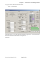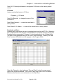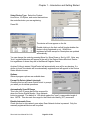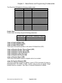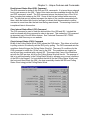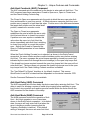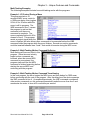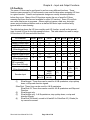
1
SilverLode™ Servo Family User Manual Revision 5.00 21 July 2009 For QuickControl Rev 5.00 SilverLode User Manual Rev 5.00 Page 1 of 159 Table of Content HOW TO USE THIS MANUAL ................................................................................................. 8 NOTATIONS .................................................................................................................................. 8 PERFORMING EXERCISES ............................................................................................................. 8 FOR FIRST TIME USERS ................................................................................................................ 8 WHAT'S NEW FOR QUICKCONTROL 5.00? ................................................................................... 9 APPLICATION RELATED INFORMATION ........................................................................................ 9 WARNINGS .................................................................................................................................. 9 TRADEMARKS ............................................................................................................................ 10 COPYRIGHT ................................................................................................................................ 11 CHAPTER 1 - INTRODUCTION AND GETTING STARTED ........................................... 12 INTRODUCTION .......................................................................................................................... 12 GETTING STARTED ..................................................................................................................... 12 Setup Start-Up Kit ................................................................................................................. 12 Install QuickControl ............................................................................................................. 12 Run QuickControl 1st Time And Setup Communications ..................................................... 13 Initialization Wizard ............................................................................................................. 14 Jog Servo ............................................................................................................................... 14 Create and Run First Program ............................................................................................. 16 DESIGN GUIDE AND HARDWARE DESCRIPTIONS ........................................................................ 20 Typical Components.............................................................................................................. 20 Default Configuration ........................................................................................................... 22 Typical Configurations ......................................................................................................... 23 QUICKCONTROL® OVERVIEW .................................................................................................... 25 PROGRAMMING OVERVIEW ........................................................................................................ 25 QUICKCONTROL® INTERFACE .................................................................................................... 26 Menus Bar ............................................................................................................................. 27 Toolbar.................................................................................................................................. 30 Program Info Toolbar ........................................................................................................... 31 Program Window .................................................................................................................. 32 Device Status Monitor........................................................................................................... 33 Device State ...................................................................................................................... 33 Right Click Popup Menu .................................................................................................. 34 Status Log.............................................................................................................................. 34 File Menu Details ................................................................................................................. 35 Program File Properties .................................................................................................... 35 Upload Program File ......................................................................................................... 37 Clone A Controller............................................................................................................ 38 Programs Menu Details ........................................................................................................ 39 Register Names ................................................................................................................. 39 I/O Names ......................................................................................................................... 40 Download and Chart ......................................................................................................... 40 Tools Menu Details ............................................................................................................... 41 Initialization Wizard ......................................................................................................... 41 SilverLode User Manual Rev 5.00 Page 2 of 159 Unknown Device Wizard .................................................................................................. 41 Control Panel .................................................................................................................... 42 Control Panel Strip Chart .................................................................................................. 45 Register Watch .................................................................................................................. 47 Data Monitor ..................................................................................................................... 48 Diagnostics ........................................................................................................................ 51 Firmware Download Wizard............................................................................................. 51 Setup Menu Details ............................................................................................................... 52 Comm Port ........................................................................................................................ 52 Register Devices ............................................................................................................... 52 Options .............................................................................................................................. 53 Comm Properties Details ...................................................................................................... 54 COM ................................................................................................................................. 54 E-485 Bridge (Ethernet) .................................................................................................... 55 Set All E-485 Bridges to Defaults .................................................................................... 55 Program Line Right Click Pop-Up Menu ............................................................................. 56 Edit Details........................................................................................................................ 56 DEVICE INITIALIZATION DETAILS .............................................................................................. 57 Phase Alignment ................................................................................................................... 57 Start-Up Phase Alignment ................................................................................................ 57 Index Phase Alignment ..................................................................................................... 57 Automatic Index Phase Alignment ................................................................................... 57 Manual Index Phase Alignment ........................................................................................ 58 Cyclic Phase Alignment .................................................................................................... 58 SilverDust I-Grade With I-Grade Motor Memory Initialization .......................................... 58 Initialization Wizard Details ................................................................................................. 59 Initialization Wizard Options ............................................................................................ 60 Initialization Scenarios...................................................................................................... 61 Tuning Wizard ....................................................................................................................... 65 Initialization File .................................................................................................................. 65 Other Initialization Files....................................................................................................... 69 TROUBLESHOOTING COMMUNICATIONS..................................................................................... 69 SilverLode Indicator LEDs ................................................................................................... 70 Green LED Flash Code ........................................................................................................ 71 CHAPTER 2 – BASIC MOTION AND PROGRAMMING FUNDAMENTALS ................ 75 TRAJECTORY GENERATOR ......................................................................................................... 75 COMMAND TYPES AND CLASSES................................................................................................ 76 COMMAND PARAMETERS ........................................................................................................... 76 Scaling................................................................................................................................... 76 Raw Numbers.................................................................................................................... 76 Position/Distance .............................................................................................................. 77 Target Velocity ................................................................................................................. 77 Actual Velocity ................................................................................................................. 77 Acceleration ...................................................................................................................... 78 Time .................................................................................................................................. 79 Torque ............................................................................................................................... 79 Filter .................................................................................................................................. 79 BASIC MOTION COMMANDS ...................................................................................................... 80 Relative Motion ..................................................................................................................... 80 SilverLode User Manual Rev 5.00 Page 3 of 159 Absolute Motion .................................................................................................................... 80 Velocity Based Motion .......................................................................................................... 80 Time Based Motion ............................................................................................................... 80 Velocity Control .................................................................................................................... 81 S-Curve Factor...................................................................................................................... 81 MEMORY MODEL ....................................................................................................................... 83 Serial Communications Buffer .............................................................................................. 83 Program Buffer ..................................................................................................................... 83 Data Registers ....................................................................................................................... 84 Non-Volatile Memory............................................................................................................ 85 Non-Volatile Memory Map .............................................................................................. 85 Storing Data Registers ...................................................................................................... 85 Storing Details .................................................................................................................. 86 RSN, RSM Store Times .................................................................................................... 86 RLN, RLM Load Times .................................................................................................... 87 Firmware............................................................................................................................... 87 Memory Management ........................................................................................................... 87 Program Size Limits ......................................................................................................... 87 Multiple Programs in QCP Files ....................................................................................... 87 Managing Non-Volatile Memory Program Storage ......................................................... 88 PROGRAM EXECUTION ............................................................................................................... 89 How Programs Operate ........................................................................................................ 89 Motion Commands ................................................................................................................ 89 Flow Commands ................................................................................................................... 89 Data Register Commands ..................................................................................................... 90 Miscellaneous and Initialization Commands ........................................................................ 90 Program Flow Control ......................................................................................................... 90 Delay (DLY) ..................................................................................................................... 90 Wait on Bit State (WBS)................................................................................................... 90 Wait on Bit Edge (WBE) .................................................................................................. 90 Jump Commands (J..) ....................................................................................................... 90 Program Call and Return (PCB, PCI, PCL)...................................................................... 91 For/Next (FOR/NXT) ....................................................................................................... 92 Enable Code ...................................................................................................................... 93 Enable State ...................................................................................................................... 94 PROGRAM DEBUGGING .............................................................................................................. 95 Debug Mode .......................................................................................................................... 95 Single Step/Break .................................................................................................................. 95 Single Step Trace .................................................................................................................. 95 Real-Time Trace.................................................................................................................... 95 Breakpoints ........................................................................................................................... 95 Real-Time Breakpoints.......................................................................................................... 95 View Thread .......................................................................................................................... 96 Register Watch ...................................................................................................................... 96 Test Line ................................................................................................................................ 96 Data Monitor ........................................................................................................................ 96 View Command Details......................................................................................................... 96 Jump To Line......................................................................................................................... 96 CHAPTER 3 – UNIQUE FEATURES AND COMMANDS................................................... 99 SilverLode User Manual Rev 5.00 Page 4 of 159 STATUS WORDS ......................................................................................................................... 99 Polling Status Word (PSW) ................................................................................................. 101 Poll (POL) Command ..................................................................................................... 102 Clear Poll (CPL) Command ............................................................................................ 102 I/O Status Word (IOS) ......................................................................................................... 103 Read I/O States (RIO) Command ................................................................................... 103 Jump and Motion Commands ......................................................................................... 104 Internal Status Word (ISW) ................................................................................................. 104 Read Internal Status Word (RIS) Command .................................................................. 105 Clear Internal Status Word (CIS) Command .................................................................. 105 Check Internal Status (CKS) Command ......................................................................... 105 Internal Status Word 2 (IS2) (SD05) .................................................................................. 106 Internal Status Word 3 (IS3) Description ........................................................................... 107 Internal Status Word 4 (IS4) Description (SD 05).............................................................. 108 Extended IO Word (XIO) Description (SD) ........................................................................ 109 ERROR LIMITS AND DRAG MODE ............................................................................................. 109 Error Limits Command Parameters ................................................................................... 109 Error Limits Operation ....................................................................................................... 109 Drag Mode .......................................................................................................................... 110 ANTI-HUNT™ FEATURE .......................................................................................................... 113 Using Anti-Hunt™ .............................................................................................................. 113 Anti-Hunt Operation ........................................................................................................... 113 Anti-Hunt™ Commands...................................................................................................... 114 Anti-Hunt Constants (AHC) Command .............................................................................. 115 Anti-Hunt Delay (AHD) Command ..................................................................................... 115 Anti-Hunt Mode (AHM) Command ..................................................................................... 115 Error Limits (ERL) and Torque Limits (TQL) Commands ................................................. 116 MULTI-TASKING ...................................................................................................................... 116 Multi-Tasking Operation .................................................................................................... 116 Servo Cycle ......................................................................................................................... 116 Multi-Tasking Operation Rules........................................................................................... 118 MULTI-THREAD (SD17) .......................................................................................................... 122 Using QuickControl To Launch Thread 2 .......................................................................... 123 CLC, CTW, CLX, CLD, WCL, AND WCW COMMANDS ........................................................ 125 WCW and WCL Commands ................................................................................................ 127 CHAPTER 4 – MOTION CONTROL USING INPUTS AND REGISTERS ..................... 129 USING INPUTS TO STOP MOTION .............................................................................................. 129 Standard Stop Conditions - QuickControl .......................................................................... 130 Standard Stop Conditions – Serial Communications ......................................................... 130 Stop Enable ..................................................................................................................... 130 Stop State ........................................................................................................................ 130 Advanced Stop Conditions .................................................................................................. 130 REGISTER BASED MOTION COMMANDS ................................................................................... 131 Register Moves .................................................................................................................... 131 Extended Register Moves .................................................................................................... 131 Profile Moves ...................................................................................................................... 131 Registered Step and Direction (RSD) ................................................................................. 131 Input Modes ........................................................................................................................ 131 SilverLode User Manual Rev 5.00 Page 5 of 159 CHAPTER 5 – ADVANCED TOPICS ................................................................................... 135 TECHNIQUES FOR STOPPING MOTION ....................................................................................... 135 Software Stop Options......................................................................................................... 135 Hardware Stop: Drive Enable feature ............................................................................... 136 PROFILE MOVE OPERATION ..................................................................................................... 136 PROFILE VELOCITY CONTINUOUS (PVC) ................................................................................. 138 INPUT MODE COMMANDS ........................................................................................................ 139 INTERPOLATED MOTION CONTROL .......................................................................................... 139 REGISTER FILES ....................................................................................................................... 139 CAMMING ................................................................................................................................ 139 TORQUE CONTROL ................................................................................................................... 139 SHUTDOWN AND RECOVERY .................................................................................................... 139 SERIAL COMMUNICATIONS ...................................................................................................... 139 SERVO TUNING ........................................................................................................................ 140 CHAPTER 6 – INPUT AND OUTPUT FUNCTIONS.......................................................... 141 INPUT AND OUTPUT OPERATION .............................................................................................. 142 I/O Lines.............................................................................................................................. 142 I/O Functions ...................................................................................................................... 143 Digital Inputs and Outputs.................................................................................................. 144 Analog Inputs ...................................................................................................................... 144 High-Speed I/O Functions .................................................................................................. 145 Synchronous Serial Interface (SSI) ..................................................................................... 145 I/O Conflicts ........................................................................................................................ 146 USING DIGITAL INPUTS ............................................................................................................ 147 General Digital Inputs ........................................................................................................ 147 Motion Control Inputs......................................................................................................... 147 Kill Motor on Input ............................................................................................................. 147 Modulo Trigger Input (SilverNugget Only) ........................................................................ 148 Configure I/O (CIO) Configure I/O Command .................................................................. 148 Configure I/O Immediate (CII) Command .......................................................................... 148 Digital Input Filter (DIF) Command .................................................................................. 148 USING DIGITAL OUTPUTS ........................................................................................................ 148 General Digital Outputs ..................................................................................................... 148 Configure I/O (CIO) Command .......................................................................................... 149 Configure I/O Immediate (CII) Command .......................................................................... 149 Set Output Bit (SOB) Command ......................................................................................... 149 Clear Output Bit (COB) Command..................................................................................... 149 USING ANALOG INPUTS ........................................................................................................... 150 USING ENCODER SIGNALS WITH DIGITAL I/O .......................................................................... 150 Encoder Signal Types ......................................................................................................... 150 Step and Direction Signals.................................................................................................. 151 Step Up/Step Down Signals (SilverNugget Only) ............................................................... 151 A and B Quadrature Signals ............................................................................................... 151 EXTERNAL (SECONDARY) ENCODER INPUTS ............................................................................ 152 Direct Motion Control Inputs ............................................................................................. 152 Dual Loop Control .............................................................................................................. 152 ENCODER OUTPUTS ................................................................................................................. 153 Internal Encoder Output (SilverNugget Only) ................................................................... 154 SilverLode User Manual Rev 5.00 Page 6 of 159 Internal Encoder Output (SilverDust-IGB Only)................................................................ 154 Internal Encoder Output (SilverDust-IG8 Only) ................................................................ 154 Scaled Internal Encoder Output (Modulo Output)(SilverNugget Only) ............................. 154 SYNCHRONOUS SERIAL INTERFACE (SILVERDUST IG8 ONLY) ................................................. 156 INDEX........................................................................................................................................ 157 SilverLode User Manual Rev 5.00 Page 7 of 159 How to Use This Manual How to Use This Manual The SilverLode™ Servo Family User Manual is a technical reference designed to aid users in the operation and programming of the SilverLode™ product family which includes the SilverNugget™ and SilverDust™. QuickControl®, QuickSilver‘s software interface, is used for programming, initializing and testing the SilverLode products. The companion publication, SilverLode™ Servo Family Command Reference, provides details on all commands. The User Manual frequently references the commands and discusses their operation. For this reason, both publications are needed to understand the SilverLode™ products. The User Manual material is arranged in a textbook format. It begins with the fundamentals of use and progresses into advanced topics that are application oriented. Any new user can follow the material in a natural progression of product usage. In addition, there are exercises throughout the text that provide users a hands-on approach toward understanding the topics better. The manual is thorough, but not exhaustive. Users that explore this material fully and complete the exercises should gain the ability to operate, program, and prototype any SilverLode servo system into working applications. Notations SDnn This notation means the feature or command being described was introduced in SilverDust rev nn. Performing Exercises The exercises in this manual are designed for use with one SilverLode servo, a PC running QuickControl, an acceptable power supply, and a basic QCI Start-Up kit (or comparable circuitry for I/O triggers). Many of the examples require the toggling of inputs. To perform these exercises, the user will need to wire in a switch. The inputs used are 1, 3 and 5. Alternatively, the user could purchase a Training Breakout (QCIBO-T) which already has these switches built-in. The Training Breakout connects to the SilverLode's SMI Port using a SMI cable. See individual datasheets for more details. For First Time Users Chapter 1 gives step-by-step instructions on the hardware setup and first time operation, including initialization and writing a simple program. SilverLode User Manual Rev 5.00 Page 8 of 159 How to Use This Manual What's New For QuickControl 5.00? QuickControl 5.00 supports that latest SilverDust firmware rev 45. Major Features: Status Device Monitor Redesign o Max number of registered devices extended from 6 to 64. o Actual Position displayed for each device o Right Click Popup Menu for each device Restart Stop Reg Watch Manual Reg Devices Zero Status Log widened and sizable Register Watch: Move registers up/down, sort Find feature added to search QCPs for text (Edit->Find) Tuning Wizard added to Initialization Wizard New or Enhanced Commands (see Command Reference for Details) o SMD: Set Mode Application Related Information Detailed application programming examples are available with the QuickControl software. They are found in a subfolder of the main QuickControl install folder named ―QCI Examples‖. QuickControl can be downloaded from the QCI website www.QuickSilverControls.com. The website also contains QCI Application Notes that offer the user details of operation in specific applications. Warnings The QuickSilver Controls, Inc (QCI) SilverLode servos are high performance motion system. As with any motion system, it is capable of producing sufficient mechanical output to cause bodily injury and/or equipment damage if it is improperly operated or if it malfunctions. The user shall not attach a QCI product to any mechanism until its operation is fully understood. Furthermore, the user shall provide sufficient safety means and measures to protect any operator from misuse or malfunction of the motion system. The user assumes all liability for its use. Do Not Hot Plug The SilverLode Product! Connecting or un-connecting hot wires or plugs is defined as Hot Plugging. A hot wire is a wire with voltage on it. When this occurs, the residual current in the power circuitry (motor windings, power supply, voltage clamp, 5 Volt supply, communication power…) attempts to find the path of least resistance to ground (before the proper ground connection is established). In most cases this path is through the communication lines (but is not limited to communication failure). The available protection devices are not rated for high transient power spikes, or repeated spikes. Repeated spikes can weaken communication slowly to the point of failure. In some cases, total communication failure can occur in the first and only instance of Hot Plugging. In applications, this can be overcome by connecting chassis ground to the power supply ground. With this direct ground implemented, the ! SilverLode User Manual Rev 5.00 Page 9 of 159 How to Use This Manual path of least resistance for residual power is through the added chassis ground. In applications where chassis ground is isolated from power ground, take EXTREME care not to Hot Plug. Contact QCI if necessary. ! User must remove motor from load before initializing the servo or aligning motor index pulse to prevent potential injury or damage. If Index Phase Alignment option is used, the user must re-run the Initialization Wizard after replacing either motor, encoder, and/or driver; motor must be removed from load prior to powering up system after changing any of these elements to prevent potential injury or damage. Start the wizard with the power turned off, and turn on power when instructed. ! ! Units shall not be used in life critical applications without the signed authorization of the President of QuickSilver Controls. ! User is responsible to provide safety interlocks for any application that may cause injury or damage in either normal or abnormal operation of the unit. ! The SilverNugget N3 must be wired with a voltage clamp (i.e. QCI-CLCF-04) between the N3 and the Driver power supply; the SilverNugget N2 and SilverDust D2 MG may require a clamp, according to the application. The voltage clamp must be placed close enough to the SilverLode controller/driver to guarantee that the voltage difference between the module and the clamp at maximum current never exceeds 1.5 Volts. (This includes the drop across both the power and ground conductors.) ! Do not mechanically back drive the motor of a SilverLode servo without a voltage clamp present. The voltage generated may damage the electronics. ! User shall limit current to the SilverNugget N3 units to no more than 35A, or shall fuse power to the SilverNugget N3 using a slow acting fuse rated at not more than 35A. ! These products are intended to be used with the appropriate power supplies, motors, electrical protection components and other equipment to form a complete end product or system. They must be installed by a professional assembler who is familiar with the requirements for safety and electromagnetic compatibility (―EMC‖). The products are to be tested in the final application at the system level. The assembler is responsible for ensuring that the end product or system complies with all the relevant laws in the country where it is to be used. Trademarks QuickControl® and QCI® are Registered Trademarks of QuickSilver Controls, Inc. SilverLode User Manual Rev 5.00 Page 10 of 159 How to Use This Manual SilverLode™, SilverNugget™, SilverDust™, PVIA™, QuickSilver Controls™, and AntiHunt™ are trademarks of QuickSilver Controls, Inc. Copyright The SilverLode servo family's embedded software, electronic circuit board designs, embedded CPLD logic, and this User Manual are Copyright 1996-2009 by QuickSilver Controls, Inc. SilverLode User Manual Rev 5.00 Page 11 of 159 Chapter 1 – Introduction and Getting Started Chapter 1 - Introduction and Getting Started Introduction The chapter starts out with a Getting Started section that describes setting up and using QCI‘s Start-Up kits. This is a quick way for first time users to get up and running. The remainder of the chapter details other hardware setups and documents the QuickControl interface. Getting Started In order to facilitate designing a QCI® servo into an application, QCI has put together several start-up kits. These kits include the most common items necessary to get things started. When matched with a user supplied power supply, computer and motor/encoder, the Start-Up Kit allows a user to immediately start programming and testing. WARNING: Read Warnings section at the beginning of this manual before connecting any hardware. Setup Start-Up Kit Setup the hardware following the instructions included in the Start-Up Kit. A copy can be downloaded from our website (www.QuickSilverControls.com). Install QuickControl After the hardware is setup, install QuickControl as follows: Hardware Requirements Personal computer with a Pentium (at least 500Mhz) or higher processor running Windows 2000, XP, or Vista. An unshared serial port capable of communicating at 57,600 Baud or better (USB to serial adapters ok). An Ethernet connect for SilverDust with Ethernet. QuickControl Software on CD. Note: QuickControl can control a SilverLode™ product in ―real-time‖; it therefore needs full access to PC resources. When installing QuickControl, it is necessary to close all shared files and exit open applications. It is also highly recommended that applications requiring large system resources be closed and any screen saver disabled. Background tasks can cause interference and should be reduced to minimum requirements. Procedure 1) Insert the QuickControl CD into the CD ROM drive. If QuickControl setup automatically runs, go to step 4. 2) From the Start menu select SilverLode User Manual Rev 5.00 Page 12 of 159 Chapter 1 – Introduction and Getting Started Start > Run 3) Type in the setup program: [CD Drive Letter]: \setup 4) Follow the instructions on the screen. 5) Remove CD and reboot the PC. This can be done by selecting: Start > Shut Down Run QuickControl 1st Time And Setup Communications Run QuickControl: From the Start menu, Start > Programs > QuickControl If your comm port has not yet been enabled (true for any first time users), QuickControl will prompt you to enable the Comm Port and initialize your servo. Press OK. Press OK. Check Enable if COM1 is ok. The Comm Port can also be setup from Setup menu (see Setup Menu Details in this manual for information on changing COM ports or setting up Ethernet). Press OK. Verify your hardware is setup correctly (See Setup Start-Up Kit above). Do not connect the motor to a mechanical load until you are familiar with its operation and established any necessary safety interlocks. If your unit requires a clamp or clamp resistor, connect them now. Power up device and press OK. This will launch the Initialization Wizard. SilverLode User Manual Rev 5.00 Page 13 of 159 Chapter 1 – Introduction and Getting Started Initialization Wizard The wizard can also be launched from the Tools menu. Enter the Motor Cable Length in the feet. This can be found on the last two digits of the cable part number. For example, a QCI-C-D15P-D15S-04 is a 4‘ cable. Press "Download File To Device" to initialize the servo using factory defaults. See Initialization Wizard (below) for more details. A message will appear when the download is complete. Press OK to acknowledge message. Press ―Save As‖ to save the file with a name meaningful to you. Press ―Exit w/ Save‖. Initialization is complete! Note, there are lots of example programs to look at in the QCI Examples folder (installed when QuickControl was installed in the QuickControl folder). Jog Servo If you are communicating with your servo, you should see a green ―Prog Stop‖ tag in the device‘s ―Pos/State‖ cell. This means you are ―polling‖ and have a registered device. If you see something like what is shown on the left, press the ―Scan Network‖ on the Device Status Monitor. SilverLode User Manual Rev 5.00 Page 14 of 159 Chapter 1 – Introduction and Getting Started To jog your servo, select from the main menu: Tools -> Control Panel Using the mouse, run ―Jog Vel‖ slider up and down to jog the servo. See Control Panel later in this manual for more details on using this tool. Press Exit. SilverLode User Manual Rev 5.00 Page 15 of 159 Chapter 1 – Introduction and Getting Started Create and Run First Program Move 8000 Counts At Power Up We will create a new program that causes the servo to go 8000 encoder counts when it powers up. You should be polling and have a registered device. In other words, you should have a green ―Prog Stop‖ in the Device Status Monitor (see Setup Communications). If your status is not green, press Scan Network on the Device Status Monitor Create a new program by selecting New Program File from the File menu. File -> New Program File Your screen should look like this. On the Program Info Toolbar, press Add. The Select Program Line dialog box will appear. Press the MOVE tab. Double click on MRT. The Edit Move dialog box will appear. SilverLode User Manual Rev 5.00 Page 16 of 159 Chapter 1 – Introduction and Getting Started Edit the move data as shown. Press the OK button to save and exit. On the Program Info Toolbar, press Download. QuickControl will download your program to the servo's non-volatile memory. Cycle power to your servo or press Restart. Your servo will restart and go 8000 counts in 1 sec. The program you just wrote will execute every time the servo powers up. Select Save As from the File menu to name and save your program. Congratulations! You are a programmer. Stop a Move Using a Digital Input To make the move stop depending on the state of a digital input, the move needs to be edited. 1) Select the MRT program line. 2) Press the Edit button on the Program Info Toolbar. 3) Press the Stop Condition button. 4) Select the Standard tab. 5) Select I/O #1 and LOW/FALSE. The dialog box should look like the following: This will cause your move to stop when Input #1 is LOW. 6) Press OK to save and exit. 7) Press OK to exit the Edit Move dialog box. SilverLode User Manual Rev 5.00 Page 17 of 159 Chapter 1 – Introduction and Getting Started 8) Press the ―Download/Restart‖ button on the Program Info Toolbar and verify the move stops when Input #1 goes LOW. NOTE, the Run button is shortcut that first "presses" the Download button for you followed by the Resart button. 9) Power down and power up your servo and verify the program runs again. Start a Move Using a Digital Input There are many ways to start a move using a digital input. Most of them involve adding a Program Flow command to the program. We will add a command that will cause the servo to wait until Input #5 is LOW before executing our move. 1) With our MRT command selected, press the Insert button to add a line between line 1 and 2. (note: pressing Add will add a line below the selected line). The Select Program Line dialog box will appear. 2) Select the FLOW tab. 3) Double-Click on the WBS command. This command will cause the servo to wait at the program line until the condition is met. 4) Enter the data as shown. 5) Press OK to save and exit. 6) Press ―Download/Restart‖ to run your program with Input #5 HIGH. Note, the servo does not move until Input #5 goes LOW and will stop when Input #1 goes LOW. Do Forever To make the program start back over again after it finishes the move, we will add a JMP command (FLOW) to the end. 1) Select the MRT program line. 2) Press the Add button. 3) Select the Flow tab. 4) Select the JMP command. SilverLode User Manual Rev 5.00 Page 18 of 159 Chapter 1 – Introduction and Getting Started 5) In the label field, enter the word ―START‖ as shown on right. 6) Press OK to exit the Edit Jump Command dialog box. 7) You have just added a command to jump to the program line with the label ―START‖. Add this label to line number 2 by clicking on the line 2 label cell and type ―START‖. The JMP command will now loop to line 2 after it finishes the move. 8) With both Input #1 and Input #5 HIGH, run the program. Verify the motor does not spin until Input #5 goes LOW. Verify the motor executes its move until Input #1 goes LOW. 9) Save the program under a name of your choice. You can look at a fully documented version of the program by opening: QCI Examples\ Using Inputs for Move Selection\Tutorial-Using an Input to Start and Stop a Move.qcp SilverLode User Manual Rev 5.00 Page 19 of 159 Chapter 1 – Introduction and Getting Started Design Guide and Hardware Descriptions This section documents typical hardware components and setup configurations for SilverLode servos. Typical Components For most applications, the following generic parts list provides a complete motion control servo system. These components give the basic functionality necessary for a working rotary positioning system. This basic system is comprised of a QCI Controller/Driver, QCI Motor/Encoder, Breakout Module, Power Supply, and Cabling. Some items could be added or removed from this list, but the items listed are the ones used most often. For detailed examples on using any particular controller/driver in a system, please refer the SilverLode Controller/Driver Datasheets on our website (www.QuickSilverControls.com). Controller/Driver The servo controller/driver is the main component in the servo system. QCI‘s control algorithm allows the controller/driver to servo high torque stepmotors with load inertia mismatches well over 100:1. Each controller/driver has such capabilities as serial communications, Input/Output lines and Mathematical functions. Non-volatile Memory allows multiple programs to be saved indefinitely for later recall. A SilverLode controller/driver drives a single stepmotor. Stepmotor/Encoder QCI offers high pole count stepmotors with encoders. When matched with a SilverLode driver/controller, the combination creates a high-performance rotary positioning system. Each stepmotor has been specifically selected for optimized performance with the SilverLode drivers. Motor/encoder packages are typically selected based on the torque performance of the stepmotor, environmental rating and the required encoder resolution. Power Supply SilverLode products operate from a supply voltage of +12 VDC to +48 VDC and must be initialized for the specific operating voltage. The power supply can be a switching or linear type, but should be chosen so that the power output meets or exceeds the power requirement of the SilverLode product. Check the product datasheets for maximum current specifications. Unregulated supplies are not recommended due to the wide swing of the input power line causing wide swings in the output voltage. SilverLode User Manual Rev 5.00 Page 20 of 159 Chapter 1 – Introduction and Getting Started Minimum Power Supply Specifications Regulated Supply ± 5 % Output Tolerance ± 2.0 % Load Regulation 50V Maximum Over Current Fold-Back Protection Short Circuit Protection Over Voltage Protection Cabling QCI offers cabling for use with SilverLode servos and accessory products for general applications. These cables have documentation describing physical dimensions and pinouts. If an application requires custom cabling, the correct pinout must be used to develop the correct wiring harness. The following are some design requirements that are incorporated into standard QCI cables but could be easily overlooked when manufacturing custom cabling. Shielding—I/O and communication lines are susceptible to noise in many industrial environments. Grounding— SilverLode products have logic, processor, power, and chassis grounds that must be wired correctly. Null modem connections—the transmit line on a SilverLode product is connected to the receive line on a serial port and vise versa for the receive line on SilverLode product (RS-232). Sound electrical junctions—it may be beneficial to use crimp style connectors rather then the solder tail type to avoid unintentional solder bridging across adjacent pins. Lines with poor electrical junctions could cause intermittent contacts that could effectively Hot Plug the device and disable communications. Shorts between power and other pins may damage the unit. Wire gage—ensure lines meet the specified current and voltage drop requirements. Voltage Clamp – Usually Only Required for SilverNugget When a SilverLode servo is back driven or decelerates, the servo acts as a generator, producing electrical power from the absorbed mechanical power. The SilverLode controller/driver has to get rid of this power somehow, otherwise it will pass to the power supply input raising the power supply voltage. If the voltage becomes too high, it can damage the servo controller as well as the power supply. To prevent such damage, the power must be directed to a load where it can be safely dissipated. This is the function of the voltage clamp. When the voltage clamp determines that excess power is being generated by the attached servo, it redirects this excess power to a load resistor. Some controller/drivers use an external voltage clamp while others have one built in. See individual datasheets for more details. It is highly advised that, for those controllers without a built in voltage clamp, an external one be installed at the engineering/prototype phase. The ―clamp active‖ LED should be SilverLode User Manual Rev 5.00 Page 21 of 159 Chapter 1 – Introduction and Getting Started monitored during rapid decelerations, including emergency stops and simulated recovery from jamming (also, if the end user can manually push a slide or spin a load, these conditions should be checked as well). If the clamp active LED lights during these tests, the clamp is required in the final design. See Technical Document QCI-TD017 High Current Clamp Module - QCI-CLCF-04, QCICLOF-04 for information concerning the voltage clamps. Hosts SilverLode products can communicate with a myriad of motion control hosts and devices. All SilverLode product serial interfaces, baud rates, and protocols are software configurable. This flexibility allows the SilverLode servo to communicate with many host and software package available. In addition, several SilverLode servos can be connected together to form a network. Default Configuration When shipped from the factory, the SilverLode product and QuickControl software are initialized with default values that are used to establish initial communications between device and a PC. These default values can be changed to different settings during the initialization procedure. Unit ID Supply Voltage Serial Communications Protocol 16 48VDC 8 Bit ASCII Serial Interface RS-232 Baud Rate 57600 For SilverDust controllers with the E-485 Bridge (Ethernet) option, Unit ID Supply Voltage Serial Communications Protocol 16 48VDC 8 Bit ASCII Serial Interface RS-485 Baud Rate 57600 IP Address DHCP SilverLode User Manual Rev 5.00 Page 22 of 159 Chapter 1 – Introduction and Getting Started Typical Configurations The following describes typical configurations for SilverLode servo systems. This section is not an all-encompassing list. There are many variations and additions that are possible. However, these examples should provide a good starting point. For detailed examples on using any particular controller/driver in a system, please refer SilverLode Controller/Driver Datasheets on our website. Standalone Configuration SilverLode servos are capable of operating as a system-level controller without any input from a master controller or user interface. To function in this manner, SilverLode servos are pre-programmed to produce the desired motion and to respond to any sensors or other inputs in the system. Often in this configuration, the digital I/O is used to initiate the required operations by programming the product to start, end, or select programs using different I/O combinations. Host Configuration Host configuration involves a SilverLode servo that is entirely controlled by a host PC, Programmable Logic Controller (PLC), Human Machine Interface (HMI), or other such device. The host is connected to the device through the RS-232/485 serial port or the E-485 Bridge (Ethernet). In this configuration a host controller such as a PC or PLC provides commands to the device. The device waits for each command to be sent, executes the command, and then waits for the next command. After the initialization routine has completed, no additional internal program stays running that would allow the device to perform an operation by itself. Most commands are available to the host. Some commands, such as Jump (JMP) or Program Call (PCL), are only for use inside programs downloaded into the device. Operation in host configuration mode has the SilverLode configured as a passive slave to the host controller, waiting for each command before performing any operation. This allows for extended operations not available in a SilverLode only network. In cases where many axes of control are required, a host configuration can achieve very complex or highly coordinated multi-axis control. A host controller can also retrieve data from registers. Hybrid Configuration A hybrid configuration utilizes a SilverLode servo operating such that the servo receives command from an external controller, executes internal programs, and uses its internal I/O . This configuration is more versatile than either a pure standalone or pure hostcontrolled configuration. The SilverLode product can use its standalone abilities to execute internal programs and interact with the system through its I/O. Also, an external host can issue commands or interact with programs. For example, a PLC could direct the device to switch tasks or stop motion in response to a digital input or serial command from the PLC. SilverLode User Manual Rev 5.00 Page 23 of 159 Chapter 1 – Introduction and Getting Started Multiple SilverLode Servo Configurations A SilverLode product can be part of a small RS-232 or a larger RS-485 network. In addition, two or more devices can be interconnected through their I/O lines. The possible configurations for multiple device systems are seemingly endless, although all of the configurations are just combinations of the two basic configurations listed in this section. Many of the advanced applications for SilverLode products use this capability. SilverLode User Manual Rev 5.00 Page 24 of 159 Chapter 1 – Introduction and Getting Started QuickControl® Overview SilverLode products have an extensive command set that allow them to be programmed for a wide variety of complex applications. SilverLode products need to be preprogrammed if they are to be used in a standalone or hybrid configuration. In host configuration, the host issues commands directly to the servo for execution and no user program (other than initialization) is stored in the non-volatile memory. SilverLode products are programmed from a series of commands issued through a serial communications link. The most practical way to program a SilverLode product is to issue these commands from the QuickControl software running on a PC. QuickControl is QCI‘s Windows-based software interface for the SilverLode products. QuickControl can run on a Windows 9x, NT, ME, 2000, or XP based PC connected to a SilverLode product using one of the PC‘s serial ports. QuickControl is designed to make programming SilverLode products easy and efficient. Programming a SilverLode product and using its advanced features is the topic of most of this manual, and QuickControl is used in nearly all of the examples. It is also the only programming interface fully supported by QCI and is always required to change the factory default initialization program. Programming Overview The command set is accessible by most devices capable of communicating over an RS232 or RS-485 serial connection (including the E-485 Bridge). This means that almost all host controllers (HMI, PLC, Vision, and PC systems) can be used to communicate with and control SilverLode products. Many applications require commands to be sent from the host directly to a SilverLode product. This type of control is usually prototyped and tested more efficiently using QuickControl. For example, an application might require a custom program written in C++ running on a PC to dynamically issue a series of commands to a device connected to the PC. SilverLode product operation could be setup for this application without the use of QuickControl, but the development and prototyping of the application is easier, faster, and more accurate if done with QuickControl. Programs are made up of two components: the initialization program and user programs. The initialization program contains all the initialization settings as well as default settings for some of the advanced functions. User programs contain the instructions to be followed while operating in standalone or hybrid configuration. • Initialization Program. The initialization program starts at the first memory location in non-volatile memory (address 0). After a device powers up, it automatically executes the program that starts at the first memory location. This program must contain initialization instructions for the SilverLode product or it will not operate properly. Every SilverLode product comes from the factory with a default initialization in the proper memory location. QuickControl has several tools for safely changing the default initialization. The last command in the default initialization program is a command to load and run the program that starts at memory address 512. This is the default location for the start of the first user program. SilverLode User Manual Rev 5.00 Page 25 of 159 Chapter 1 – Introduction and Getting Started • User Programs. User programs give a SilverLode product much of its true power. User programs are integral to the standalone and hybrid configurations, since in those configurations, the logic and control load is entirely or partially shifted to the SilverLode product. User programs are formed by linking commands together. The command set includes commands for program flow, logic and math functions, memory manipulation, as well as numerous commands to control the motion of the SilverLode product. QuickControl includes tools to aid in creating programs, as well as an on-line description of each command. QuickControl® Interface The main QuickControl screen offers the user an easy to use programming interface with the ability to monitor the communications status of up to 6 active units connected to the PC Host. An active status log is available for viewing the status information the active device is sending to the host. In addition, any device connected to the host can be selected in order to view current position and the active I/O states. The Main QuickControl Screen is divided into five major sections (see figure below). 1) The Menu Bar contains pull down menus with all the functions of QuickControl. 2) The Icon Bar contains the most often-used menu items as shortcuts. 3) The Program Info Toolbar displays programming and program information. 4) The Program Window displays the active program. 5) The Status Log displays messages. 6) The Device Status Monitor provides information about all connected devices. 1 2 SilverLode User Manual Rev 5.00 3 4 Page 26 of 159 5 6 Chapter 1 – Introduction and Getting Started Menus Bar The QuickControl Menu Bar provides access to all functions of the software. These ―pull down‖ type menus offer many selections that can bring up other menus to accomplish certain objectives. Above the Menu Bar, next to the QCI logo & QuickControl name is the active filename being displayed in the QuickControl Program Window. See Menu Details below for more information. File Menu New Program File - Opens blank program template New Sequence File – Advanced Feature (see Technical Document QCI-TD025: Events and Sequences). Open – Opens a saved file Close – Closes the active file in QuickControl Save – Saves the current file Save As – Saves the current file with user set parameters Program File Properties – Contains scaling, password protection, and user defined names. This dialog box can also be accessed by pressing Scaling on the Program Info Toolbar. See File Menu Details below for more information. Upload Program File – Retrieves the current program residing in non-volatile memory. See File Menu Details below for more information. Print – Prints the active QuickControl Program file to the default printer Print Setup – Allows the user to change printer and paper settings All Halt – Sends the All Halt command Recent Files – Displays a list of files recently open in QuickControl Exit – Closes the current files opened and exits QuickControl Edit Menu Cut – Removes highlighted section of text or program line Copy – Copies highlighted section of text or program line Paste – Inserts a copied or cut section of text or program line before selected line Select All – Highlights an entire program Events – Advanced Feature (see Technical Document QCI-TD025: Events and Sequences). Find – Find (search for) text in program file. View Menu Toolbar – When checked, Toolbar will be displayed Status Bar – When checked, Status Bar will be displayed Device Status – When checked, Device Status will be displayed Column Width – Set the program's column widths SilverLode User Manual Rev 5.00 Page 27 of 159 Chapter 1 – Introduction and Getting Started Program Menu Add Line – Adds a new line to a program Insert Line – Inserts a line above the selected line in a program Edit Line – Edits the selected program line Edit Line Details - Edits the selected program line with all the command details. Delete Line – Deletes the selected line in a program Disable Line – Disable selected line in a program. The program line is "grayed out" and is not downloaded. Enable Line – Enabled a disabled line. New Program – Creates a new blank program Delete Program – Deletes selected program Program Details – Allows a user to name, describe, and modify the stored location of a program. Scaling – Allows a user to adjust scaling parameters and max/min ranges Register Files – Links register files or file arrays (.txt based) to active QuickControl program (see Register Files for more details). Register Names – Assigns user defined names to registers. See Programs Menu Details below for more information. I/O Names – Assigns user defined names to I/O lines. See I/O Names below for detail. See Programs Menu Details below for more information. Download – Download program file to device. Download/Restart - Download program file to device then restart device. Download/Run - Download program file to device then run first program without restarting. Run w/o Download - Download program to RAM then run. Download and Chart - Download program file to device then bring up chart. See Download and Chart below for more information. See Programs Menu Details below for more information. Erase Application in Device – Erases current program in non-volatile memory Toggle Breakpoints – Toggles Breakpoint at current line Clear all Breakpoints – Clears all Breakpoints in all programs Single Step - Single step program line. See Program Debugging for details. Real-Time Trace - Trace Program in Real-Time. See Program Debugging for details. Jump To Line – Jump program execution to selected line. SilverLode User Manual Rev 5.00 Page 28 of 159 Chapter 1 – Introduction and Getting Started Tools Menu Initialization Wizard – Sets up and initializes devices. See Tools Menu Details below for more information. Unknown Device Wizard – Establishes communications with a device of unknown parameters. See Tools Menu Details below for more information. Control Panel – Tool for Jogging, Tuning, and Monitoring SilverLode products. See Tools Menu Details below for more information. Register Watch – Change and/or view data in the SilverLode products data registers with this utility. See Tools Menu Details below for more information. Data Monitor – Monitor all data sent and received by a device and the PC. See Tools Menu Details below for more information. Diagnostics - Displays the real-time states of all the commonly used status words. Firmware Download Wizard – Downloads firmware to device. See Tools Menu Details below for more information. Setup Menu Comm Port – Selects Baud Rate, Communications port, and Protocol for QuickControl. See Setup Menu Details below for more information. Register Devices – Allows user to manually register devices into QuickControl. See Setup Menu Details below. See Setup Menu Details below for more information. Options – Allows user to edit other setup specifications. See Setup Menu Details below for more information. Polling – When checked, starts QuickControl polling the network for any connected devices and then displays the state of the device in the Device Status window Window Menu New Window – Creates a new program window Cascade – Cascades current program windows Tile – Displays current program windows in a tile arrangement Arrange Icons – Arranges and aligns minimized program icons Current Program List – A list of programs currently open in QuickControl Help Menu Help Topics – Opens help menu for tutorials and information on QuickControl About QuickControl – Displays date and version of QuickControl and product support information SilverLode User Manual Rev 5.00 Page 29 of 159 Chapter 1 – Introduction and Getting Started Toolbar The QuickControl Toolbar provides shortcuts to certain functions that may be used repetitively while using the QuickControl software. 1 2 3 4 5 6 7 8 9 10 11 12 13 1 Create a New Program File (.QCP). 4 Save the Active Program File (.QCP) to PC's Hard Drive. 7 Cut Selected Lines From Program File 2 Open an Existing Program File (.QCP). 3 Close the Active Program File. 5 Initialization Wizard 6 Control Panel 7 Copy Selected Lines From Program File 9 Print Active Program 11/12 Ver/Help 8 Paste Previously Cut or Copied Line into Program File 13 Stop all motion/executing programs on all devices. STOP The STOP button stops all command execution and programs running in all devices connected to the PC. It can also be used to verify communications to any device as the Red LED blinks briefly when issued. (Will not affect units running Modbus® protocol.) SilverLode User Manual Rev 5.00 Page 30 of 159 Chapter 1 – Introduction and Getting Started Program Info Toolbar The Program Info Toolbar is located on the left side of the main QuickControl Screen. This toolbar allows the user to create, edit, download, and debug programs. It also offers information about programs and the current device being programmed. Program Line Add (Ctrl-A) – Adds a line below selected line Edit (Ctrl-E) – Edits the selected line Insert (Ctrl-I) – Inserts a line above selected line Delete (Ctrl-D) – Deletes the selected line Programs Download – Downloads all programs in the active file to the device. Download/Restart – Downloads all programs in the active file to the device and commands the device to restart. Download/Run – Downloads all programs in the active file to the device and commands the device to load and run program 0 Run w/o Download – Runs first program in active file (program 0) but does not download anything to non-volatile memory. Scaling – Shortcut to Program File Properties. Test Line – Executes selected line. Debug – Opens Debug Toolbar (see Program Debugging latter in this manual for details). Program List The list of selectable programs currently open in the active QuickControl file (QCP) No. of words used window Shows how many words are being used in the currently displayed program Device To Program Restart – Restarts the currently selected device Desc – Allows user to select the device being programmed and displays the registered label and ID number Type – Displays type of device currently being programmed SilverLode User Manual Rev 5.00 Page 31 of 159 Chapter 1 – Introduction and Getting Started Program Window This area of the QuickControl Screen displays the active program opened. It is where all program lines are created, viewed, and edited. The interface allows the user to single click on the line to highlight that particular line or double click on the line to edit the contents (parameters) of that line. 1 2 3 There are three columns in the Program Window. 1) Line Number and Operation – Displays the program line number and the Three Letter Acronym (TLA) of the command. 2) Label – Allows the user to put in labels for branching operations in programs. 3) Command – Provides a brief summary of the command on that line and the parameters that are set in that specific operation of the command. In this example of the Program Window, there are two colors used to differentiate the lines of the program. Blue is used for actual commands and green is used for the remarks (REM). Remarks are not downloaded with the commands and are only used for documenting a QCP. When a label is placed on a REM line, the label is effectively moved to the next command line. If the label is placed on a REM line that is at the end of a program it will be the next available command line up from that REM line. In the example above, ―START‖ is a label on line 1, a REM line. The program branches to the START label from Line 4 when the I/O condition is met. Since line 1 is a REM line, when this program is downloaded to the device the START label will actually point to line 2, the next command line after the REM line. SilverLode User Manual Rev 5.00 Page 32 of 159 Chapter 1 – Introduction and Getting Started Device Status Monitor The Device Status Monitor occupies the right hand portion of the main QuickControl window. It provides status information on QuickControl and the attached devices. Active Device The status of the active device (selected by pressing any cell in the Device Status List) is displayed anytime polling is running. This includes the current position of device and the I/O Status. If the device ID button is pressed (i.e. ID=16), the Register Watch tool will come up. Device Status List This portion of the display is used as a quick reference to the Registered Devices. QuickControl uses a polling routine to check the status of these devices. Each device has four (4) cells which contain the following data: Unit ID Description Actual Position Device State Controller Motor Unit ID: Device‘s Unit ID Description: The devices description is user editable from the Manual Register dialog box (Setup->Register Devices). Actual Position: Actual position of motor (register 1) Controller: Controller type Motor: Motor type Device State The device can have the following states: SilverLode User Manual Rev 5.00 Page 33 of 159 Chapter 1 – Introduction and Getting Started Not Pol: Not polling (press Scan Network to start polling) Prog Stop: Polling active. No program running in device. Prog Stop-Kill: Polling active. No program running in device. Device had an error and is in a Kill Motor state (shutdown). See Technical Document ―QCI-TD052 Shutdown and Recovery‖ for more details. Prog Stop-Soft Limit: Polling active. No program running in device. Device is limiting motion in response to the parameters set in an SSL or VLL command (see Command Reference for more details). Prog Run: Polling active: Program running in device. Prog Run-Kill: Polling active: Program running in device. Device had an error and is in a Kill Motor state (shutdown). See Technical Document ―QCI-TD052 Shutdown and Recovery‖ for more details. Prog Run-Soft Limit: Polling active: Program running in device. Device is limiting motion in response to the parameters set in an SSL or VLL command (see Command Reference for more details). Scan Network/Stop Polling Button Selecting the button initiates a network scan for active devices. It will scan device identities that are within the Autoscan ID Range, which is adjustable in the Setup – Options menu. The Polling Status field next to the button will display the current polling state. The label on this button will display ―Scan Network‖ when polling is stopped, and ―Stop Polling,‖ while polling is on. Right Click Popup Menu Right click on a device in the Device Status List and popup menu will appear allowing you more options to control and monitor the device. Diagnostics (see Tools->Diagnostics) Restart: Restart device. Stop: Stop all motion and programs. Reg Watch (see Tools->Register Watch) Manual Reg Devices (see Setup->Register Devices) Zero: Zero device‘s encoder. Status Log This area of the work area provides information on the operation of QuickControl and attached devices. Note, its size can be changed to see more messages. SilverLode User Manual Rev 5.00 Page 34 of 159 Chapter 1 – Introduction and Getting Started File Menu Details Program File Properties The QuickControl software provides automatic scaling to normal engineering units. It also makes command and parameter generation a simple point-and-click process. By default, distance is displayed in counts, velocity in counts per second (cps), acceleration in cps per sec (cps/s), and time in milliseconds(ms). The basic distance unit can be adjusted by clicking the Scaling button. This brings up the Program File Properties window. All contents of the Program File Properties window are stored as part of the qcp file. Scale: If the software is polling, clicking the ―Get CPR‖ button will adjust the software to the resolution of the currently selected encoder. Adjusting the value in the ―Scale‖ field will divide all position/distance, velocity, and acceleration values in QuickControl by the number. A simple example is to put 8000 in this box. This scales the display to revolutions when using a 8000 count per revolution encoder. For display purposes the string in the ―Units‖ box can be changed to anything. In this case, ‖revs‖ is appropriate. The first letter in the ―Units‖ box is used in velocity and acceleration units. The velocity unit would be scaled and changed to rps, while acceleration will be changed to rps/s. The ―# Dec Places‖ box adjusts the accuracy of the scaling used in QuickControl. For some applications, it is convenient to scale the software to a linear unit appropriate to the system. For example, it could be adjusted to cm based on the actual system output. Register and I/O Names: Press these buttons to change the default names of the registers and I/O. Description: This optional field is provided for additional user documentation. See Chapter 4 for more details. SilverLode User Manual Rev 5.00 Page 35 of 159 Chapter 1 – Introduction and Getting Started Min/Max: Min/Max fields are provided for the developer to put reasonable limits on movements. These are scaled units, so a value of 100 here would correspond to 100 revolutions if a scaling factor of 8000 was chosen. o Many of the command edit screens use sliders to aid in editing.. The slider ranges are determined by the min/max entered here. o Note, the Min/Max only affect how move commands are edited. They do not limit the actual servo movement. For example, with a Pos Max of 100 revs, the servo could be programmed to do a single 100 revolution relative move over and over. The absolute servo position can and does go well beyond these ―editing‖ min and max values. o The Vel and Acc maximum are edited in percent of the maximums. The actual engineering values are displayed for reference only. o Max Time is used for editing time parameters such as the time based move commands. Upload Password: The 4 to 10 character alpha-numeric word is downloaded with the QCP to the servo and is required to upload the program from the servo. The desired password is set in the ―Upload Password‖ box, the default is ―1234‖. o NOTE: The password helps secure your program but does not provide absolute protection. Sort Programs in Download Order: Check this box to force the Program Info Toolbar to list the Programs in Program Download Order. On Allow Run w/o Download: Check this box to only allow running the program with out downloading. The Program Info Toolbar‘s ―Download..‖ buttons will be disabled. This is useful to ensure a user does not accidently download a file that is only designed to run temporarily from RAM. Update Device Status Properties… By default, this is checked and causes the Device Status Monitor to switch to the scaling of the active QCP file. Since the tools Register Watch and Control Panel have the same scaling and register names as the Device Status Monitor, keeping this box checked forces them to reflect the properties of the active QCP. The only time this box is unchecked is for initialization files (i.e. Factory Default Initialization.qcp) to keep them from changing the user‘s scaling and register naming when opened as part of the control panel or the Initialization Wizard. Thread 2: Specifies how Thread 2 memory will be allocated. When Thread 2 programs are used, they must share the Program Buffer with Thread 1 programs. Auto (default) allows QuickControl to allocate Thread 2 Program Buffer space. If Auto is unchecked, the user must specify how much to allocate. See MultiThread latter in the manual for more details. SilverLode User Manual Rev 5.00 Page 36 of 159 Chapter 1 – Introduction and Getting Started Upload Program File The programs and data stored in a device may be uploaded as long it was programmed with QuickControl rev 4.0 and higher. NOTE: QuickControl does not download any documentation to the device. Uploaded programs will therefore have no documentation (i.e. remarks, labels, scaling, ….). To upload from a device, select: File -> Upload Program File Press ―Upload Program from device‖. QuickControl will then ask for the password used for the file when it was downloaded. This is set in the Program File Properties dialog box (File Program File Properties). The default is ―1234‖. Press OK to start the upload. If the upload is successful, QuickControl will ask you to where you want to save the application file. Name the uploaded program and press Save. The uploaded initialization program can be found in: C:\Program Files\QuickControl\QCI Initialization\ Initialization – Upload.qcp If the application had Register File Arrays, the data will be uploaded into a text file in the same folder as the QCP labeled: <your filename> - reg files.txt. Note, this Run Initialization Wizard using SilverLode User Manual Rev 5.00 Page 37 of 159 Chapter 1 – Introduction and Getting Started Clone A Controller If the application program is all that needs cloning, just download the uploaded application file. If the controller initialization and application needs cloning: 1) Verify the same motor (same part number) is being used with both controllers. 2) Run Initialization Wizard using one of the default init files 3) Download ―Initialization -Upload.qcp‖ (Programs->Download) 4) Download application file. SilverLode User Manual Rev 5.00 Page 38 of 159 Chapter 1 – Introduction and Getting Started Programs Menu Details Register Names QuickControl allows for editing the names of registers 11 through 199 (user registers). Any user registers used in a QCP file can be re-named to add more meaning to the program code. For example, registers being used for a specific function, like a loop counter can be named as such, just like the Input Mode registers and the Profile Move registers. If the QCP file does not use Profile Move or Input Mode functionality, these registers can be re-named. Access the Register Names dialog window from the Programs pull down menu or from within the Scaling dialog window found in the Program Info Toolbar. Edit Selected Register Name Select a register from the list box on the left and press Edit Selected Register Name button to re-name it. Press Reset Register Name to Default to reset the name back to factory default. Input Mode Registers (12-18) By default, these registers already have descriptive names because they are used in the PIM, VIM and TIM commands. If these commands are not being used, registers 1218 can be used as general purpose user registers. Press Set Name to User to set registers 12-18 to the name ―User‖. Press Set To Descriptive Names to set registers 12-18 back to their factory default names. Profile Move Registers (20-24) By default, these registers already have descriptive names because they are used in Profile Move commands (i.e. PMV and PMC). If these commands are not being used, registers 20-24 can be used as general purpose user registers. Press Set Name to User to set registers 20-24 to the name ―User‖. SilverLode User Manual Rev 5.00 Page 39 of 159 Chapter 1 – Introduction and Getting Started Press Set To Descriptive Names to set registers 20-24 back to their factory default names. I/O Names Assigns user defined names to I/O lines. Programs I/O Names Press Edit Selected… to change the name of the selected I/O. Press Reset Selected … to reset the name back to factory default. Press Reset All I/O Names … to reset all the names back to factory default. Download and Chart Download and Chart allows the user to download and strip chart a QCP file. When this item is selected, the active program is downloaded to non-volatile memory just as if the Download button was pressed. Program 0 is then downloaded to the Program Buffer. The chart is then opened allowing for the user to select channels. Pressing ―Run and Chart‖ issues a RUN which runs the program in the Program Buffer. Select the Channels to chart and press ―Run and Chart‖ to start the program and capture the requested channels. See Control Panel Strip Chart in the Tools Menu Details section below for more information on the Strip Chart. SilverLode User Manual Rev 5.00 Page 40 of 159 Chapter 1 – Introduction and Getting Started Tools Menu Details Initialization Wizard All SilverLode products must go through the Initialization Wizard at least once before operation or anytime a new type of motor/encoder is used. See Initialization Wizard Details latter in the chapter for details on using this wizard. Unknown Device Wizard Background At power up and before the Initialization Program is executed, the device first sets the Baud Rate to 57600, and selects the 9-Bit Binary protocol with RS-232 interface and delays for 96 milliseconds; then it switches to the 9 bit protocol with RS-485 interface and delays for 96 milliseconds; next it switches to 8-Bit ASCII protocol with RS-485 interface and delays for 96 milliseconds, and finally it switches to 8-Bit ASCII protocol with RS-232 interface and delays 96 milliseconds. This power up procedure allows the power supplies to settle and also allows a host controller to establish communication with the device using 57600 baud and either 8-Bit or 9-Bit protocol, and either RS-232 or RS-485 interfaces even if the user has selected a different interface, baud rate, or protocol in the user initialization program. A Halt (HLT) command can be sent repeatedly while the unit is powered up. When the device recognizes the command it will Halt and remain in the mode it was in at the point the Halt command was able to be received. From that point, the device is in a known state and can be initialized to the desired settings. (Note: SilverNugget units may halt on 8-Bit ASCII, RS-485 mode with an RS-232 connection, according the pull-up level on the Rx line. To bring the units to a fully known state, it is necessary to issue a SIF command setting the RS-232 protocol to ―all units‖ (ID=255).) Wizard Details When the Unknown Device Wizard is run, it prompts the user to cycle power to the device while the wizard is sending out a continuous stream of HLT commands through the Comm port. The wizard will then prompt for communication configuration of the device. These settings should match how QuickControl is configured. Note that the protocol (8-Bit ASCII or 9-Bit Binary) is determined by the settings under Comm Port in the Setup menu of QuickControl to ensure that the protocol matches QuickControl. Upon completion of the wizard, the device will be successfully communicating. NOTE: When using a SilverDust with the E-485 Bridge option (Ethernet), the wizard will take a minute or so to complete. SilverLode User Manual Rev 5.00 Page 41 of 159 Chapter 1 – Introduction and Getting Started Control Panel The Control Panel is a Tool in QuickControl that provides access to several important features. It allows the jogging of the device at scalable velocities while monitoring the condition of the device in the Device Status area of the Control Panel. Test moves are available for tuning the system when prototyping. A strip chart can be displayed to show various motion parameters and is useful while tuning. NOTE: The device to be controlled must first be registered (see Register Devices ). Device, Type, Serial # The device‘s Unit ID, description, controller type, firmware revision and serial number are displayed here. Device Status As long as Polling is running, these fields display the device‘s status in Real-Time. The fields include: Target Position: The position the servo is being commanded to. Position: The actual position of the servo. Velocity: The servo velocity. Position Error: The difference between Target Position and Actual Position. Max Error: The maximum error that occurred since last time the Zero button was pressed. Torque: The servo's torque. SilverLode User Manual Rev 5.00 Page 42 of 159 Chapter 1 – Introduction and Getting Started Driver: The driver voltage (which may be independent of the processor voltage on some units) Temp: The measured processor temperature. Tuning This section, in conjunction with the Initialization Wizard‘s Tuning Wizard, provides the tools required for tuning the servo loop (see Technical Document QCI-TD054 Servo Tuning for details). Ideally, the servo would be attached to the axis needing tuning with the real world load. Two moves are provided to allow the developer to move between two positions (ie. Extend to pickup a widget then retract back to home). Using an iterative process, the developer would do a move, examine the results on the Strip Chart, adjust the tuning parameters and start again. Cycle Press this button to cycle between Move 1 and Move 2. This is just like pressing the Move 1 and Move 2 Test buttons. If multiple cycles are desired, enter the desired number into the #Cycles field. A "0‖ in this field will make the axis cycle forever. Press the Stop button at anytime to interrupt a cycle. Enter a non-zero value in the ―ms delay‖ field, if some settling time is required between moves. Moves The four basic move types are available: MAT: Move Absolute, Time Based: Move to an absolute location in a specific time. MAV: Move Absolute, Velocity Based: Move to an absolute location at a specific velocity. MRT: Move Relative, Time Based: Move: Move some distance relative to your current position in a specific time. MRV: Move Relative, Velocity Based Move some distance relative to your current position at a specific velocity. Cycle: Select to enable Cycle (see above). See the Command Reference Manual for more details on these commands. Once your Move Type is selected, enter the move parameters and press one of the Test buttons or Cycle to execute the move. NOTE: The scale units being used are those of the selected motor. See Register Devices for more details. Jog Slider The motor velocity can be set in real-Time by sliding the pointer with the mouse. The Jog Vel field is used to set the full scale velocities at each end of the slider. NOTE: If the Shift key is pressed when the mouse is released, the servo will continue at the same velocity (it will not stop). This is useful if you want to test constant velocity application. SilverLode User Manual Rev 5.00 Page 43 of 159 Chapter 1 – Introduction and Getting Started Restart Press this button to restart the servo. Zero Press this button to zero the motor target and position. It also zeros out the Max Error latched value. STOP Press this button to stop the current sequence and motion. Motor Driver This radio button allows the motor driver to be enabled or disabled. Inputs/Outputs This displays the states of all 7 I/O Channels. A ―Red‖ I/O Channel indicator denotes a logic low and a ―Green‖ indicator denotes a logic high. If the SilverDust IGB is connected, the additional 16 I/O are also shown. Individual I/O can be Set by clicking on the respective I/O while depressing the ―SHIFT‖ key. They may be cleared by clicking on the respective I/O while depressing the ―CTRL‖ key. The I/O may be set to ―Tri-State‖ by clicking on the I/O NOTE: I/O 101 to 116: Set causes the output to be high (open drain driver turned off, only passive 5v pull-up present) while Clear causes the output to be low (open drain driver turned on); ―Tri-state‖ turns off the output driver, causing the same effect as a Set command. Analog: Displays the present voltage at each of the 4 analog inputs. Note: Analog 1 through 4 correspond to the voltages on I/O 4 through 7. SilverLode User Manual Rev 5.00 Page 44 of 159 Chapter 1 – Introduction and Getting Started Control Panel Strip Chart Open the Strip Chart from the Control Panel by pressing the Strip Chart button. Once the channels are selected, any of the following Control Panel moves will automatically be charted: Cycle Test Move 1 Test Move 2 Sample(ms) This is the amount of time to sample. Max is 15000ms. Select Channels Press this button to select the channels to chart. Up to 4 basic channels may be selected at once. Select a channel by either double clicking on it or by pressing the ―->― button. SilverLode User Manual Rev 5.00 Page 45 of 159 Chapter 1 – Introduction and Getting Started Once a channel is selected, the Select Channel Format dialog box will prompt you for the data format. This allows the Strip Chart to display data in scaled units (see Program File Properties for details). The Advanced button brings up the ―Chart YAxis‖ dialog box. Here you can set whether data will be plotted on the primary or secondary Y-Axis. If ―Determine Y-axis Min/Max…‖ is uncheck, you may manually enter the Y-Axis min/max values. Otherwise, the Y-Axis scales are set automatically. Repeat Last Move Press this button to repeat the last move. Channels ―All‖ radio select allows any of the registers to be charted. Only 64 bits of information may be selected, corresponding to (2) 32 bit channels, (4) 16 bit channels, or (1)32 bit and (2)16 bit channels. Target and Position (with no trailing register number) are sent as 16 bit channels with an algorithm to extend them to 32 bits (accurate as long as the difference is less than 32767 counts between readings); this allows additional channels to be simultaneously logged. Note that the upper 16 bits, the lower 16 bits or the entire 32 bit register may be logged by selecting the appropriate radio button. SilverLode User Manual Rev 5.00 Page 46 of 159 Chapter 1 – Introduction and Getting Started Register Watch The Register Watch Tool is a powerful tool within QuickControl for monitoring and adjusting the contents of registers. This tool allows QuickControl to simulate a host, allowing an application developer to adjust register values while a program is running within the servo. Open the Register Watch window from: Tools->Register Watch NOTE: Register Watch can also be launched by: Press the Device button on the Device Status Monitor Right Click on the device in the Device Status List. Double click on the device‘s 2nd row in the Device Status List. Press Add Register to add a register to the list of ―watches‖. The Select Register dialog box allows you to select watching the whole register or only the upper or lower half. Check Strip Chart to add a real-time strip chart and/or check Log to File to begin logging the data to a log file (log files found in Logs folder). After selecting the channel, QuickControl will allow you to select the data format which enables you to watch the data in your engineering units. Press Delete Register to remove the selected register. Press Move Up/Down to change the register order. Register Watch will watch the registers of the active device as selected in the Device Status Monitor. Change the register being watched by double clicking in the register cell. Change the data by clicking in the data cell and entering new data. Note, although the data will be changed in the indicated register, it may get overwritten if the program is SilverLode User Manual Rev 5.00 Page 47 of 159 Chapter 1 – Introduction and Getting Started also modifying the same register. If the register selectable is not writable, the value will not stay changed on the display (and will not be changed in the attached unit), and a message will appear in the Status Log portion of the screen. Change the data format by double clicking on the units. NOTE: The more registers you add to the list, the less frequent any single register will be updated. Right click on the register (row) to display a pop-up menu with many of edit features already explained plus: Column Width: Manually set width of each column High Priority: When selected for a given register watch, QuickControl disables all other background communication including all other register watches and only polls the selected register. This allows for very fast updates on one register. Advanced Press this button to allow QuickControl to monitor a communications line for any read register (i.e. RRG) commands for the selected register watches. This is useful when some other host is controlling the servo and you want to use QuickControl to monitor traffic. For example, a Human Machine Interface (HMI) is reading data from the servo but you want to see the data in Register Watch. Enable this option and to monitor the communication stream for RRG commands for any registers listed in Register Watch. Note, Polling must be off. Data Monitor The Data Monitor is a diagnostic tool that enables the user to view all transmitted and received data from all enabled ports as well as send custom packets out any single active Communication Port. The Data Monitor can be thought of as a serial or network analyzer specially designed for the QCI products. It provides the tools necessary to test your master controller‘s functionality. The fields are defined as follows: SilverLode User Manual Rev 5.00 Page 48 of 159 Chapter 1 – Introduction and Getting Started SilverLode User Manual Rev 5.00 Page 49 of 159 Chapter 1 – Introduction and Getting Started Data Display and Display Format Data is dumped to the ―Display Area‖ in one of three formats, Hex, Decimal or ASCII. Upon selection of a new format all new data will be displayed in this format. The old data will remain unchanged. Log To File When this box is checked, everything printed on the Data Display will also be logged to the text file displayed in the quotes. Do not be too worried about disk space, it can run all weekend with polling running and only fill up about 20MB. Press the Log To File button to change the log file. Data Only When this box is checked, the Data Display will only display the raw communication packets. All the time stamp and channel information will be striped off. This is useful if you want to capture a data stream for use in another program. Silent Press this button to stop collecting data. Clear Display Clears the display data. Custom Transmit The Custom Transmit feature allows the developer to build custom packets for transmission. This is very useful when testing application software. The application software can be tested for response to improperly formatted packets, fault conditions, extreme events that are hard to setup in the real world. Enter your packet in the selected Display Format. You can freely switch between Display Formats while entering a Custom Transmit packet. For example, you would like to enter the packet, ―This is a test packet‖, with a 0 at the end and a 0x02 hex at the beginning. Switch to ASCII and enter the string. Switch to Decimal, cursor to the end and enter 0. Switch to Hex, cursor to the beginning and enter 02. Your packet is complete. Switch between the three formats as much as you like. Press the Transmit button to send the packet. Add CR or Add CS or Add CRC Depending on the Communications Protocol, pressing this button will add an 8 Bit ASCII Carriage Return (decimal 13, hex 0x0D), a 9 Bit Binary Checksum, or a Modbus CRC to the end of Custom Transmit line. This is useful for creating custom packets. SilverLode User Manual Rev 5.00 Page 50 of 159 Chapter 1 – Introduction and Getting Started Diagnostics The Diagnostics dialog box displays the real-time states of all the commonly used status words. For those status words that are part of the KMX or KMC command, the Kill motor column will display ―Kill‖ if the corresponding bit was the cause of the Kill Motor. The Kill Motor ―LED‖ (top right of dialog box) will be red if a Kill Motor is in effect and green otherwise. Test Encoder Press this button and follow the instructions to have QuickControl test the encoder of the attached motor. Firmware Download Wizard The firmware can be thought of as the device's operating system. From time to time QCI adds new features to their products, which requires a new version of firmware to be downloaded. Although this can be done in the field, it is a little risky since loss of communications during the process will render the device repairable by the factory only. NOTE: SilverDust units may be recovered in the field by a special procedure – contact Tech Support if needed. The latest firmware (and instructions for downloading) can be obtained from QCI Product Support. SilverLode User Manual Rev 5.00 Page 51 of 159 Chapter 1 – Introduction and Getting Started Setup Menu Details Comm Port From the main menu, select Setup -> Comm Port, If the Communications Device Properties shows the correct communications port, check the Enable box and press OK. Press "Modify" to edit the Comm Properties. See Comm Properties Details below for more details. Register Devices QuickControl will monitor the status of a device when the device is registered into the system. Registration can be done automatically (recommended) or manually. To manually register a device, select, Setup->Register Devices Press ―Add Device‖ to manually register a device. Unit ID: Enter the device‘s Unit ID (UID). The device‘s Unit ID is entered here. Unit ID for devices must be unique. Factory default is 16. Press OK. Description: Each device should have a description so that the user can have a quick reference for the status of the device. Use only a brief description. This is the description that appears in the Device Status Monitor. Enter something that describes the device. Good examples include, X Axis, Gripper, Shuttle,… Press OK SilverLode User Manual Rev 5.00 Page 52 of 159 Chapter 1 – Introduction and Getting Started Select Device Type: Select the Product Line/Driver, I/O Option, and motor that matches the controller/motor you are registering. Press OK. The device will now appear on the list. Double clicking in the Auto cell will toggle whether the device is Auto registered or not. When Auto registered all fields except for Description are updated automatically. You can change the order by pressing Move Up, Move Down or Sort by UID. Note, any ―Auto‖ registered devices will appear at the end of the Device Status Monitor‘s Device List regardless of where they are in the Manual Register Device. Anytime Polling is started, QuickControl will automatically scan all for any devices. If a device is found, the device will be automatically registered and will appear in the Device Status Monitor screen. Options General program options are available here. Prompt On Delete (default checked) Checking this box will cause QuickControl to prompt you when you do delete operations. Automatically Scan ID Range This is the Unit ID range that will be scanned for when the Device Status Monitor, Scan Network button is pressed. The default is 1-20 which makes the "scan" a reasonable length of time. NOTE: This also sets the range for the SilverLode Identify (IDT) command. Disable Automatic Scan Check this box to skip network scan when Scan Network button is pressed. Only the manually registered devices will be polled. SilverLode User Manual Rev 5.00 Page 53 of 159 Chapter 1 – Introduction and Getting Started Comm Properties Details Communication Port Properties can be edited from. Setup ->Comm Port->Modify COM This tab is for editing the properties of the PC's COM port (i.e. COM1, COM2 …). COM Port Pull down the list box or type in the desired COM port. NOTE: QuickControl only lists what it thinks are valid COM ports. Baud Rate PC baud rate ranges from 9600 to 115K. Default is 57.6K. It is a good idea to leave it here unless you are familiar with serial communication. Protocol Each port needs to know how to communicate with the devices connected to it. The protocol sets up the Comm port so that it can send and receive data in the proper format. The protocols listed are the ones currently supported. They include: QuickSilver 8-Bit ASCII QuickSilver 9-Bit Binary Modbus® NOTE: Changes to Baud Rate and Protocol only affect the PC. They do not affect the attached device. You must use the Initialization Wizard to change the parameters in the device. In other words, if you want to start talking to the device at 9600 baud, you will first have to change the baud rate for the device, and then change the baud rate for the computer. Stop bits and parity are also edited here. SilverLode User Manual Rev 5.00 Page 54 of 159 Chapter 1 – Introduction and Getting Started E-485 Bridge (Ethernet) This tab is for editing the properties of the optional E-485 Bridge. The E-485 Bridge is a module on the controller that accepts standard Ethernet and converts or "bridges" it to the controller's RS-485. E-485 Bridge IP Address Enter the IP address of the E-485 Bridge you want QuickControl to connect to. Alternatively, you can press "Browse" to have QuickControl browse the local subnet for devices with E-485 Bridges. See "Set All E-485 Bridges To Defaults" below if "Browse" does not find an attached device. Configure E-485 Bridge Configure the E-485 Bridge with the above IP address. Note, the following functions configure the E-485 Bridge on the attached controller. The bridge will use the new configuration both now and on future power ups. Change Adr (default DHCP): Allows the user to change the E-485 Bridge's IP address or configure it to use DHCP. Set Baud Rate (default 57.6K): Allows the user to change the E-485 Bridge's RS-485 baud rate. This is the baud rate the E-485 Bridge will use to communicate to both the local servo controller and any other controllers attached to the RS-485 network. Note, the controller's baud rate (i.e. BRT command) must match the baud rate set here. Set To Default: Press this button to download the factory default configuration to the E-485 Bridge. Note, this only configures the E-485 Bridge and does not alter the controller's memory. Set All E-485 Bridges to Defaults Press this button to download the factory default configuration to all E-485 Bridges on the local subnet (see "Set To Default" above). This is sometimes required before QuickControl can "Browse" a device. For example, if a device was previously configured for IP address 10.10.10.200 and was then moved to subnet 10.10.20, "Browse" would not find it. For additional information on the E-485 Bridge, see Technical Document ―QCI-TD056 E-485 Bridge – Ethernet‖. SilverLode User Manual Rev 5.00 Page 55 of 159 Chapter 1 – Introduction and Getting Started Program Line Right Click Pop-Up Menu Right clicking on the a program line will bring up a menu with the following items: Add: Add a new program line below this line. Insert: Insert a new program line above this line. Edit: Edit this program line. Edit Details: Edits the selected program line with all the command details. Delete: Delete this line. Disable: Disable this line in a program. The program line is "grayed out" and is not downloaded. Enable: Enabled a disabled line. Expand/Collapse: Expand or Collapse this Combo Command. Test: Executes this line. For example, if the line was a move command, the attached servo would move. Column Width: Set the column widths. Toggle Breakpoint: Add/Delete Breakpoint for this line. Jump To Line: Jump program execution to selected line. Copy: Copy this line. Cut: Cut this line. Paste: Paste a previously copied or cut line. See Program Debugging latter on in this manual for more information on Breakpoints and Jump To Line. Edit Details Edit Details displays a detailed edit dialog box for the selected command. The following two dialog boxes edit the same command. Edit Details SilverLode User Manual Rev 5.00 Page 56 of 159 Chapter 1 – Introduction and Getting Started Device Initialization Details Device Initialization is accomplish using the Initialization Wizard described earlier in this chapter. This section documents some of the details being done by the Initialization Wizard "behind the scenes". Phase Alignment Commutation is accomplished using the position of the encoder with respect to the motor's rotor. This relationship is called Phase Alignment. Start-Up Phase Alignment Every time the servo powers up, the initialization program (i.e Factory Default Initialization.qcp) calculates a Start-Up Phase Alignment by moving the motor back and forth a little. It can then go closed loop and begin to servo. This works well as long as the motor is allowed to move. If your application has conditions that may stop the motor from freely moving at startup, improved Phase Alignment might be required. Examples include: Motor Brake Applied Vertical Load Motor Jammed If the motor does not move enough during the Startup Phase Align, it will calculate an incorrect phase alignment. This will cause the motor to have poor performance. It might not even be able to move, or it may move erratically. To allow Phase Alignment for these startup conditions, the alignment of the encoder with respect to the rotor must be determined a different way. The following options exist: Index Phase Alignment Index Phase Alignment uses the encoder's index pulse (z-channel) position to calculate phase alignment. For this to work, the index position with respect to the motor's rotor must be determined and saved to non-volatile memory. Automatic Index Phase Alignment For SilverDust IG/IGBs using I-Grade motors this happens automatically. The index position is determined by the factory and saved to the I-Grade motor's non-volatile memory. These SilverDust will always use Index Phase Alignment regardless whether the wizard's Index Phase Alignment option is checked. It is automatic. The alignment information is read from the attached motor each time the controller starts up (i.e. restarted), so if motors of the same type are interchanged, no re-initialization is required. NOTE: The I-Grade motors use a special encoder which have 98 transitions of the index channel spaced on a 100 spacing per revolution. (The wider ―missing‖ pulse represents the once per revolution Index location). These motors require only a slight motion before encountering an index channel transition, allowing them to quickly use the factory calibrated alignment. SilverLode User Manual Rev 5.00 Page 57 of 159 Chapter 1 – Introduction and Getting Started Manual Index Phase Alignment For all other controller/drivers, Index Phase Alignment information can only be determined by the Initialization Wizard when the Index Phase Alignment option is checked. When this option is enabled, the Initialization Wizard does a series of moves to calculate the Phase Alignment with respect to the index signal and stores the value to non-volatile memory. A drawback to this option is that the Initialization Wizard must be re-run anytime the encoder is loosened, or a different motor/encoder pair is connected. Regardless of controller, if Index Phase Alignment is used, the servo will only use the Startup Phase Alignment until is sees the index signal at which time it will read the phase alignment information from non-volatile memory. Cyclic Phase Alignment For applications that do not support Automatic Index Phase Alignment, but still need improved Phase Alignment while maintaining the ability to swap motors without rerunning the Initialization Wizard, Cyclic Phase Alignment is an option. This is a modified Startup Phase Alignment that repeats the start-up move over and over again (cyclic) until a valid Phase Alignment is determined. This works well if the motor eventually can ―wiggle‖ itself into a position where it can move a little in both directions. To use Cyclic Phase Alignment, from Initialization Wizard; open the file Factory Default Initialization - Cyclic.qcp instead of Factory Default Initialization.qcp. Make sure Index Phase Alignment is unchecked (Options). NOTE: The execution time of this init file will vary depending on how many moves are required to calculate Phase Alignment. SilverDust I-Grade With I-Grade Motor Memory Initialization All I-Grade motors currently being manufactured have non-volatile memory which has been initialized at the factory to contain such things as: Motor Type (i.e. 23H-5, 17-3, 34HC-2,….) Motor Serial Number Encoder Properties Index Phase Alignment This information is readable by I-Grade SilverDust controllers and allows for a more simplified Initialization Wizard. See Initialization Wizard Details below for more information. The SilverDust uploads the same information from the motor at startup. If the motor type does not match, the SilverDust will disable its driver and flash the green LED 4 times. To change motor types, simply connect the new motor type to the SilverDust and re-run the Initialization Wizard. The wizard will detect the new motor type and initialize the controller accordingly. SilverLode User Manual Rev 5.00 Page 58 of 159 Chapter 1 – Introduction and Getting Started Initialization Wizard Details The Initialization Wizard is used to initialize the SilverLode controllers for such things as communications, tuning, motor/encoder selection, etc. All SilverLode products must go through the Initialization Wizard at least once before operation or anytime a new type of motor/encoder is used. NOTE: If the unit has previously been initialized, you might want to start the Initialization Wizard with the controller powered down to prevent any previously downloaded programs from running. For an un-initialized device (i.e. fresh from the factory), this is not necessary. Run wizard from Tools menu: Tools -> Initialization Wizard If your unit was powered up, you should see something like the dialog box shown. If using a I-Grade SilverDust with an I-Grade motor, the motor type, encoder type, and motor serial number will be displayed. Other combinations of motors and controllers will not display this information. If the controller is not powered up, then controller and motor type will not be displayed. Device and Motor Press this button to select a different device on the network. Open, Save and Save As This section allows the user to open other initialization files, save the current file, or save the current files as a different name. QCI recommends using a unique initialization file for each application (i.e. each axis). See Initialization Details below for more detains on these files. Initialize Parameter Browser The Browser permits direct access to all commands via a categorized selection tree. This selection tree may be expanded by clicking on the ―+‖, revealing the individual commands that can be selected for editing. Exit w/o Save Exit w/ Save Depending on the option selected (see Options below), this button will exit the wizard and either save or not save the initialization file will be saved to the hard drive and exits wizard SilverLode User Manual Rev 5.00 Page 59 of 159 Chapter 1 – Introduction and Getting Started Initialization Wizard Options Selecting the Options button will allow you to change the initialization options: Restart on Download (default checked): This option selects whether the device is to be restarted automatically after each initialization file download. In order for any changes in the initialization file to take affect, the device must be restarted. The device can be manually restarted by pressing the Restart button on the Program Info Toolbar or by cycling the device‘s power. If you are changing the Identity, Baud Rate, Serial Interface, or Protocol, delaying the restart until all user programs have been downloaded may simplify the process. Maximum Velocity Scale (default 4000RPM): This option allows the user to select the default 4000 RPM or to change the velocity scaling in the system for lower top speeds. With a lower top speed, the scaling for velocity parameters as well as the actual velocity registers is changed so that a full scale value for each of these will correspond to the selected velocity. The velocity and acceleration terms in the CTC and FLC commands may need alteration (to be lowered) in your application if a value other than 4000RPM is selected. Velocity control for systems that do not need higher velocities may be improved by selecting a lower Maximum Velocity. Advanced Line Resistance (default unchecked): This option causes an addition dialog box to appear anytime a device is being initialized that allows for calculating resistance for user cables using various wire gauges. Encoder Resolution Reduction (default Divide By 1): This option is only available for SilverDust units. It is intended to allow programs written for older 4000 CPR (count per revolution) systems to be easily adapted to the newer 8000/16000 CPR motors. A divide by 1 provides the full 8000 CPR resolution when using an 8000 CPR encoder. The divide by 2 option ―downgrades‖ the resolution, so the system behaves as if a 4000 CPR encoder is attached. Save On Exit (default checked): Check this button to save the file (to the PC not the attached device) when the "Exit…" button is pressed. Note, the "Exit…" button's name with change to "Exit w/ Save" when this box is checked. Erase Application Programs (default checked): When wizard is run, the user's application programs stored in the controller are erased. This option can be unchecked as long as Index Phase Alignment is not used. The wizard must erase the user program(s) in order to make room for the Index Phase Alignment program run within the wizard. Choose Motor/Configure Encoder (default unchecked): If this option is checked, the user will be prompted to select a motor every time the wizard is run. If this option is not checked, the wizard will only prompt the user to select a motor if it thinks it needs to. Examples of this would include: o Un-Initialized Device (fresh from factory) o Index Phase Alignment Option Changed NOTE: If you want to re-initialize a controller for a different type of motor/encoder, check this option at least once. This will force the wizard to prompt for you for a new motor type. NOTE: This option is ignored when using the SilverDust IG or IGB with an IGrade Motor, as the motor type is automatically read from the non-volatile SilverLode User Manual Rev 5.00 Page 60 of 159 Chapter 1 – Introduction and Getting Started memory inside the I-Grade Motor. See SilverDust IG/IGB With I-Grade Motor Memory Initialization for details. Index Phase Alignment (default checked):If this box is checked, the servo will use the encoder index (z channel) signal to set its phase alignment at power up. If this box is not checked, the servo will rely solely on the initialization program's phase alignment. See Index Phase Alignment latter in this chapter for more details. Download File To Device Press this button to start initializing your device. Note, if the unit was powered down previous to starting the initialization process, or if the Baud Rate, Protocol, or Serial Interface do not match the connection to the PC, the Unknown Device Wizard is automatically invoked to establish communications with the device (Unknown Device Wizard is documented latter on in this chapter). Initialization Scenarios The following are typical initialization scenarios. Scenario 1: I-Grade SilverDust Controller With I-Grade Motor This is the most common and simplest case because the I-Grade SilverDust reads most of the information it needs from I-Grade motor memory. 1) Press "Download File to Device". The Initialization Wizard uploads motor ID and encoder information from the I-Grade motor memory and initializes the motor. 2) Finish A screen will appear indicating that the selected initialization qcp file has been downloaded. Select OK to exit. The unit should now be initialized and ready for operation. (It may need to be restarted if the No Restart on Download option was selected.) Press Exit to leave the Initialization wizard. SilverLode User Manual Rev 5.00 Page 61 of 159 Chapter 1 – Introduction and Getting Started Scenario 2: I-Grade SilverDust With Non I-Grade Motor 1) Press "Download File to Device". The Initialization Wizard fails to upload the motor data and displays the "Error Reading Data From Motor Memory" dialog box. 2) Error Reading Data From Motor Memory Dialog Box The following choices are presented: Continue: No Motor Memory: Select for non-I-Grade motors. Continue: Motor Memory: Select if an I-Grade motor will be used, but is not currently attached to the SilverDust. Cancel: Press " Continue: No Motor Memory " 3) Select Motor Dialog Box Select the desired motor and press Next. 4) Determine Encoder CPR (optional) If you select a non I-Grade motor, you will get this dialog box. If you know your encoders Counts Per Revolution (CPR), select it from one of the options. You can also select Test Encoder. Note selecting Test Encoder will require that the wizard rotate the motor. Press OK If you selected Test Encoder you will a message warning you about the motor moving, otherwise the wizard will finishes like Scenario 1 above. SilverLode User Manual Rev 5.00 Page 62 of 159 Chapter 1 – Introduction and Getting Started Scenario 3: SilverNugget or SilverDust MG 1) Press "Download File to Device". 2) Select Motor Dialog Box …. The rest is the same as Scenario 2 above. Scenario 4: SilverDust with Custom Motor or 3rd Party Motor QuickControl can initialize a SilverDust controller to servo most stepper motors as long as they are within the current limitations of the driver (see controller datasheet). QuickControl needs the following information: 1) Press "Download File to Device". 2) Error Reading Data From Motor Memory Dialog Box (I-Grade SilverDust Only) Press "Continue: No Motor Memory" 3) Select Motor Select "Custom Motor" for you controller. Press Next 4) Enter this information from the 3rd party motor's datasheet. Press OK. NOTE: Only edit Advanced options with QuickSilver Tech Support's guidance. NOTE: This information is stored with MCT command in the Initialization Program File (i.e. My Custom Init.qcp). 5) Determine Encoder CPR (optional) The rest is the same as Scenario 2 above. SilverLode User Manual Rev 5.00 Page 63 of 159 Chapter 1 – Introduction and Getting Started Scenario 5: I-Grade SilverDust Controller With I-Grade Motor To Be Attached in the Field Since all the pertinent motor and encoder information is contained in the motor's non-volatile memory, it is possible to initialize an I-Grade SilverDust without the I-Grade motor attached. Simply run the Wizard without the motor attached. 1) Press "Download File to Device". 2) Error Reading Data From Motor Memory Dialog Box. Select Option 2 "Continue: Motor Memory " 3) Select Motor Dialog Box Select the desired motor and press Next. 4) Finish The wizard finishes as normal. Power down the controller, attach motor and power up. As long as the selected motor matches the attached motor the controller will work fine. SilverLode User Manual Rev 5.00 Page 64 of 159 Chapter 1 – Introduction and Getting Started Motor Cable Length Enter the length, in feet, of the cable between the controller/driver and the motor. For QCI cables, the last two digits of the part number denote this length. For example, the Motor Interface Cable, QCI-C-D15P-D15S-10 is 10 feet long. Tuning Wizard The Tuning Wizard tab is used to tune the servo loop. In most cases this is not necessary. If the motor is vibrating with a load attached or is not moving smoothly, tuning is probably required. Tuning is covered in Technical Document ―QCI-TD054 Servo Tuning‖. Initialization File It is good practice to save a record of the specific power up changes made to each device as a unique Initialization file. This file should contain all the command settings for any particular device in a specific application. These commands include device specific settings like Motor Constants and Phase Constants that work with a specific type of stepmotor at a fixed operating voltage. The initialization file also contains application parameters such as the Identity, Serial Interface, Baud Rate, Kill Motor Conditions, Error Limits, etc. There should be one initialization file per axis on any multi-axis machine. The Open button selects the initialization file. When using the Initialization Wizard for the first time, the Factory Default Initialization.qcp file is automatically opened in the Wizard File window. This is a read only file and cannot be overwritten. To save any changes made to the initialization file, press the Save As button and give your file a unique name. The Initialization program file contains the following programs: Main Init The Main Initialization program contains all of the initialization commands for the device. This program is shown in the next section and is described in detail. Startup Recovery The Startup Recovery is used if a Kill Motor Condition is tripped during execution of the factory default initialization. The default program, disables the driver and flashes the green LED once. See SilverLode Indicator LEDs latter in this chapter for flash definitions. Kill Motor Recovery This program is called whenever a condition set in the Kill Motor Conditions (KMC) command is tripped. This may be modified if special processing is required. The default program, disables the driver and flashes the green LED twice. See SilverLode Indicator LEDs latter in this chapter for flash definitions. For example, if the device is required to set an error output anytime it detected a jam, Moving Error needs to be set in the KMC command because a mechanical jam will induce moving error. An appropriate error limit must also be set via the ―Error Limits‖ SilverLode User Manual Rev 5.00 Page 65 of 159 Chapter 1 – Introduction and Getting Started command. Finally, add a Set Output Bit (SOB) command to the Kill Motor Recovery program. Power Low Recovery This program is called whenever voltage drops below the specified threshold in the Low Voltage Trip (LVT) command and may be modified if special processing is required on a Power Low condition. The default program, disables the driver and ends the program. Flash Seq A utility program that flashes the green LED the number of times specified in register 11. The program is called by the error programs to flash the LED. See SilverLode Indicator LEDs latter in this chapter for flash definitions. Factory Block Fault This program is run when a fault has occurred in the Factory Block (see Memory Model for details on Factory Block). This program simply adjusts to flash sequence to correspond with the other faults and runs the Flash Seq program. See SilverLode Indicator LEDs latter in this chapter for flash definitions. Factory Default Initialization File Details The following is a summary of the initialization commands contained in the default file. For more information on any of these commands, please see the Command Reference. IDT – Identity Each device needs to have a unique unit identity to establish communication to a single drive. Values between 1 and 254 may be chosen for these identities. Multiple devices may have the same group identity to communicate with multiple drives at once. The group identity must be different from any individual identity on the network. NOTE: The allowable range is limited by the option "Automatically Scan ID Range" (see Options). PRO – Protocol Select either 8-Bit ASCII, 9-Bit Binary, or Modbus communication protocol. See Technical Document QCI-TD053 Serial Communications on our website for a complete discussion on differences between communication protocols. SIF – Serial Interface Choose either RS-232 or RS-485 serial communications hardware interface. See Technical Document QCI-TD053 Serial Communications on our website for a complete discussion on differences between serial interfaces. (The Auto check box within this command automatically configures the serial interface to match the interface currently setup in the device. If changing the interface type, uncheck the box or no change will occur.) BRT – Baud Rate Change the BAUD rate of the device. This does NOT change the PC‘s baud rate. Select Normal mode to choose from a list of baud rates. ADL – ACK Delay SilverLode User Manual Rev 5.00 Page 66 of 159 Chapter 1 – Introduction and Getting Started This command sets the time delay the device waits before sending an Acknowledgement (ACK), Negative Acknowledgement (NAK), or data to the Host PC after the device receives a command. MCT – Motor Constants This command initializes the driver stage to produce appropriate drive signals to the device. It is dependant on both the motor type and the supply voltage. The Initialization Wizard does this automatically. Auto is the default setting and recommended by QCI. FLC – Filter Constants These constants select the cutoff frequency for the velocity and acceleration tuning filters. These filters help minimize high frequency noise. The default values can be changed by un-checking the Use Default For Device checkbox. These values are modified when using the QuickControl Control Panel for tuning. See Technical Document QCI-TD054 Servo Tuning on our website for information on tuning. CTC - Control Constants This command sets the various servo loop gains used for tuning. Variations of these constants, in conjunction with the Filter Constants, allow oscillation and error to be minimized. See description and Command Reference for definitions. These values are modified when using the QuickControl Tuning Tool. See Technical Document QCITD054 Servo Tuning on our website for information on tuning. GOC - Gravity Offset Constants This command sets a custom gravity offset term in the servo control loop for vertical load applications. The gravity-offset value increases torque by the given amount for moving loads against gravity and decreases torque by the given value for moving loads with gravity. DIR – Direction This command allows the user to select whether Clockwise or Counterclockwise rotations will correspond to positive motion values. Viewing motor from the shaft end references the direction. This command can only be issued in the initialization program before the motor alignment section while the servo is in open loop (do not issue again in a user program). TQL - Torque Limits This command changes the torque limit settings for the different control states of the device. The limit caps the maximum value the device may use. Specify the limit as a percent or check the Maximum box next to each slider to maximize the parameter. AHC – Anti-Hunt Constant Anti-Hunt mode is an open loop mode that allows the device to eliminate dither. The AHC command sets the thresholds used to determine if the position is sufficiently close to the target to allow the device to go into and to stay in Anti-Hunt mode. SilverLode User Manual Rev 5.00 Page 67 of 159 Chapter 1 – Introduction and Getting Started AHD – Anti-Hunt Delay Set the Anti-Hunt time delays switching from closed loop to open loop at the end of a motion following the point that the error is below the specified limit. Prevents switching too early while mechanical vibrations are still settling out. SCF – S-Curve Factor Choose the S-Curve characteristics in the acceleration portion of motion profiles. The SCF command uses a sixteen-bit value (0-32767) to corresponding to selections from a Trapezoidal profile to a full S-curve. LVT – Low Voltage Trip Allows for a low voltage threshold to cause the device to stop operation or load and run a program defined by the Power Low Recovery (PLR) command. This allows for proper shut down when power is lost, or for data storage in power loss situations. OVT – Over Voltage Trip Like LVT, except for this command sets the maximum allowable voltage, going above which will cause the device to kill or shut down. OVT is tied to the Kill Motor Conditions to setup a kill enable when the voltage is exceeded. ERL – Error Limits Choose the application error limits for Moving Error, Holding Error, and the Delay to Hold time. Enable Drag mode operation by checking the Drag Mode box. Values are tied to the Kill Motor Conditions (KMC) command to setup a kill whenever an error limit is exceeded. KMC – Kill Motor Conditions Enable options to shutdown the Device under certain conditions. To select the conditions, press the button next to the desired option until it matches the desired state (i.e. Disable, TRUE, or FALSE). After tripping an enabled condition in the KMC, a Kill Motor Recovery (KMR) routine, if configured, is automatically loaded and run. DIF – Digital Input Filter Select the filter time for any or all of the digital inputs. The filter ensures valid I/O states by ignoring noise and spikes on the signal lines that could trigger a state change if the I/O line was to react instantaneously. Select individual I/O lines (or all lines) to set the filter constant. LRP – Load and Run Program Specify the next non-volatile address to load and run a user program. The default is non-volatile address 512 (the first open location after the initialization). Download the first user program into this location, and the Initialization program will load and run it automatically. SilverLode User Manual Rev 5.00 Page 68 of 159 Chapter 1 – Introduction and Getting Started Other Initialization Files In addition to the Factory Default Initialization.qcp file, QuickControl comes with the following read only default initialization files. Depending on your application, it may be beneficial to start with one of these rather than ―Factory Default Initialiation.qcp‖. Factory Default Initialization - CAN.qcp Use this to enable QCI‘s CANopen® protocol. See CANopen® User Manual for details. CANopen® and CiA® are registered community trade marks of CAN in Automation e.V. Factory Default Initialization - CT2 FL2.qcp The servo tuning parameters CTC and FLC are replaced with the new improved CT2 and FL2. See command reference for details on these commands. Factory Default Initialization – Cyclic SN.qcp Initialization file used for Cyclic Phase Alignment on SilverNugget controllers. See Phase Alignment above for details. Factory Default Initialization - Cyclic.qcp Initialization file used for Cyclic Phase Alignment on SilverDust controllers. See Phase Alignment above for details. Factory Default Initialization – H/W Driver Enable.qcp Initialization file that waits for H/W driver enable before initializing. This file should be used if the hardware driver enable is used on such servos as SilverNugget N3, SilverDust IGB, and IG8. Factory Default Initialization – N2 Driver Enable.qcp Special version for SilverNugget servos with "driver enable" option, including options E4, E5, M4 and M5. See Technical Document QCI-TD015 Driver Enable – Input 3 for details. Factory Default Initialization - Open Loop.qcp This file is used for a devices operating in open loop only. No encoder. See Technical Document QCI-TD047 SilverDust Open Loop for details. Troubleshooting Communications With the SilverLode product powered up, start QuickControl and the polling routine should automatically find the device. If QuickControl is already running and the device is powered up, press the ―Scan Network‖ button to find the device on the network. If ―No Devices Found‖ appears in the Device Status Monitor, either the device has been initialized with something other than the Factory Defaults (listed in the Hardware Requirements section of this chapter) or QuickControl is not set up to communicate with the device in its present communications state. Some things to check if this happens are: • • Verify the COM port being used to connect to the device. Under Setup, select Comm Port / Comm Channels and ensure the baud rate and protocol are set to Factory Defaults (57600 and 8 bit ASCII respectively). Also, SilverLode User Manual Rev 5.00 Page 69 of 159 Chapter 1 – Introduction and Getting Started • • • • • • confirm the Enable checkbox is checked and the COM Channel enabled is the one device is connected to. Verify there are no other programs using the port (only one program can control a COM Port at any given time). These can include other motion control drivers or programs used for communication devices (e.g. Palm Pilot, HyperTerminal etc.). If these programs do not relinquish control of the port, QuickControl will report ―Could Not Open select COM Port‖ and ―Access is denied.‖ errors in the Status Log. Under Setup, select Register Devices and ensure all six devices have the Auto Reg checkbox checked. Run Tools Unknown Device Wizard (only works with one device connected at a time) If networking multiple devices, QuickControl can only register six at a time for viewing. If networking multiple devices, each has to be initialized with the Initialization Wizard with a unique ID. Under Setup, select Options and make sure the Autoscan ID range encompasses the ID of the units desired. Reduce Baud Rate. If you are occasionally loosing communications with the device, try reducing the baud rate. Remember to change both the PCs baud rate (Setup->Comm Port) and the device's (Init Wizard->Communications->Baud Rate). After verifying the integrity of the COM Port and making any necessary changes, try a quick communication test. Stop the QuickControl polling routine (if it is running), and press the red hand icon (STOP) button on the QC toolbar. The red LED on the back of device should flash briefly as it receives and processes the Halt command sent to it each time the STOP button is pushed. This simple test can be done at any time to verify that the device is receiving commands. It is also good to verify that the Windows PC can communicate through the serial port without QuickControl. Programs like HyperTerminal can accomplish this (see Technical Document QCI-TD024 8 Bit ASCII Protocol Using HyperTerminal). If communication is successful with the third party terminal program, then QuickControl should be able to operate correctly. SilverLode Indicator LEDs There are two indicator light emitting diodes (LEDs) on the back of every SilverLode product, one red and one green. These LEDs provide the user some basic information about the current operational state. When the device is first powered up the green LED should be on (on the SilverNugget, the red LED flashes on momentarily at power up as well). The red LED is the communication/program done indicator. If the red LED is on solid (dim glow), then no program is running and the device is not communicating. When the device receives the start of a transmission, the red LED will shine extra bright. When the transmission is processed, the red LED will return to its original state. Sending the device a number of commands in succession (e.g. the QuickControl polling routine) will induce a flickering of the red LED. This flickering can occur in regular intervals or as random blinks depending on the communication scheme. SilverLode User Manual Rev 5.00 Page 70 of 159 Chapter 1 – Introduction and Getting Started If the red LED is out completely, then a program is running from an internal program in the Program Buffer (and, in the absence of flashes, no communications is taking place). The green LED is normally used to indicate motor torque, it starts out a middle brightness, glows brighter for positive torque and darker for negative torque. Its function changes if the Enable Done Low or Enable Done High command has been set; in this state, bright indicates that the motion is complete and the error is within set limits, while off indicates that the above are not true. The green LED is also used to flash error codes in the case of power low, over temperature, etc. according to the user and/or initialization program loaded. This is done by disabling the driver, setting open loop mode, and then setting the ―torque‖ high and low (though with the motor drive disabled, only the LED is affected). Green LED Flash Code Number of Flashes 1 2 3 4 5 6 7 Fault Startup Recovery Program Kill Motor Condition occurred at startup. Kill Motor Recovery Program Kill Motor Condition occurred after startup as a result of a condition in the KMC or KMX command. Initialization Wizard needs to be run. I-Grade Motor Memory Read Error I-Grade Motor Memory Version is Not Compatible I-Grade Motor Miss-Match. Attached motor does not match with device. Re-run Initialization Wizard I-Grade Motor Memory Checksum Fault The SilverDust IG and IGB also have a third yellow LED. This yellow LED lights to indicate that the encoder signals are not at valid levels indicating shorts, opens, or otherwise invalid levels. A bit in the Internal Status 2 (IS2) word indicates this state, and may be used to trigger a kill motor via the KMX command. (See IS2 and KMX.) SilverLode User Manual Rev 5.00 Page 71 of 159 Chapter 1 – Introduction and Getting Started Exercise 1.1 – Basic Default Initialization This exercise demonstrates how to accomplish a basic initialization of the device using the Factory Default Initialization File. 1. To initialize the device using the wizard, begin by choosing ―Initialization Wizard‖ under the ―Tools‖ pull down menu. 2. Verify the filename ―Factory Default Initialization.qcp‖ is listed in the File box. 3. Verify Motor Cable Length is correct. 4. Select the ―Download File To Device― button to have the default initialization file downloaded to the device. 5. The servo will automatically restart and the parameters will then become active on each successive power up and motor restart cycle. 6. The Program Downloaded screen will appear when downloading is complete. Press the ―OK― button to clear the message screen. 7. To exit the Initialization Wizard, select the ―Exit w/o Save― button on the screen. 8. If polling is stopped, press the ―Scan Network‖ button to verify proper communications and polling of the device. SilverLode User Manual Rev 5.00 Page 72 of 159 Chapter 1 – Introduction and Getting Started Exercise 1.2 – Using the Register Watch Tool This exercise explores the operation and use of the Register Watch Tool. 1. QuickControl must be polling for the tool to function. If the word ―none‖ appears at any time in the data section of the Register Watch Tool, then polling is not active; to establish polling press ―Scan Network‖. The Register Watch Tool is started by selecting Tools > Register Watch. By default, no registers are displayed. 2. To add a register to the display press the ―Add Register‖ button. This brings up the Select Register window. Select the register to monitor/modify from the scrolling list. Some are combo-registers, where the upper 16 bits and lower 16 bits contain separate pieces of information. These registers are named (by default) ‗high word | low word.‘ For example, register 7 contains two velocity values and is named ―Velocity 1 | Velocity 2.‖ To view only one half of register, select either ‗Upper Word‘ or ‗Lower Word‘ from the Display section. 3. Select register 5 ‗Delay Count‘ and ‗Register‘ to view the timer register. Press OK to bring up the format window. Select the desired data format. Long and ULong display the exact contents of the register with no units. This is useful for inputting basic numbers, or for viewing SilverLode native units. The Hex option translates the contents from decimal to hexadecimal. This format allows easier analysis of individual register bits. Position, Acceleration, Velocity, and Time options all scale the register value using the current QuickControl units. For information on native units and QuickControl scaling, see chapter 2. Select ‗Long‘ to display register 5 in native units. 4. Clicking OK a final time places the register into the tool. Click on the data box of register 5 (which currently contains a zero). Enter a numeric value of 10,000 or greater. Once the value has been typed, press enter. At that moment, the value typed in will be transmitted to the servo, and immediately begins decreasing. The Delay Count register is a specialized register that is automatically decremented each servo cycle. As demonstrated here, QuickControl is also constantly reading registers and reporting their contents in the register watch tool (while polling). 5. The register watch tool can be very powerful if applied well. Repeat the steps to add register 5 to the tool again, but select ‗Time‘ in the format window. 6. The tool now displays register 5 twice. Data entered in either of the data fields will be transmitted to the servo. On the next QuickControl polling cycle, the other field will be updated and contain a scaled version of the edited field. This provides a convenient method for monitoring both SilverLode native units and the QuickControl scaled engineering units. SilverLode User Manual Rev 5.00 Page 73 of 159 Chapter 1 – Introduction and Getting Started Exercise 1.3 – QuickControl Utilities This exercise demonstrates two of the most widely used utilities within QuickControl in an effort to show their usefulness in prototyping as well as troubleshooting. Upon completion of this exercise, an understanding of how QuickControl interfaces with the device should be developed. <CR> = carriage return. Since the carriage return does not have a viewable character it is displayed as a vertical bar ―|‖ when ASCII strings are viewed in QuickControl. 1. Initialize the device and press the Start Polling button to ensure functioning communication. 2. Click on Data Monitor in the Tools pull down menu and view the polling routine that QuickControl uses to report all information about the device. Note that the device never initiates outward communication. Therefore, every piece of information displayed in QuickControl has to be polled out of the device by this routine. 3. Check the Data Only box. With this box checked, the Data Monitor only displays the command strings that QuickControl sends to the device and the device response to those commands. With this box unchecked, each data string is preceded by TX/RX indicator (TX for QuickControl transmissions and RX for the device responses) and a recycling clock time. The purpose of the clock is to tell how much time has passed in between a QuickControl TX and the device RX. • The TX and RX are redundant because any transmission to the device is indicated with an @ symbol followed by the ID of the unit (e.g. @16). • the device responses are preceded with either a ―*‖,‖ #‖, or ―!‖ character (See Technical Document QCI-TD053 Serial Communications on our website for a discussion on the individual meanings of each). 4. Check the Silent box to stop the polling routine from streaming in the Data Monitor and scroll up in the window to view the routine in detail; or, check the Log to File box and press the Log to File button to select a specific location and text file to log this routine to. 5. Note the commands used in the basic polling routine (look them up by command number in the Command Reference if necessary) and the data registers that are queried. • @16 12 1<CR>: This Read Register (RRG) command queries the Actual Position[1] register. • Actual Position is displayed in the Device Status Monitor and is updated due to this line of the polling routine. 6. Click on Register Watch in the Tools menu and Add Register when the Register Watch utility appears. Choose Accumulator[10] (or a register that is not being polled by the basic polling routine) and select long format to view values as signed decimal numbers. • Uncheck the Silent box in the Data Monitor and note that Accumulator[10] is now being queried by the polling routine. 7. Type a ―50‖ into the data box of the added register and press enter. Quickly check the Silent box and scroll up in the Data Monitor log to view the transmission. • @16 11 10 50<CR>: This Write Register command writes a 50 into the Accumulator[10] register. • This string was issued by QuickControl as soon as data was typed into Register Watch and Enter was pressed. 8. Move to the Custom Transmit section of the Data Monitor. Type ―@16 11 10 100 ‖ in place of ―Test Packet.‖ Add the final carriage return character with the Add CR button, and press Transmit. • Notice that Register Watch is immediately updated by the polling routine. • Note how the Data Monitor and Register Watch tools can be used to emulate a PLC, HMI, or other host that sends data serially to the device. SilverLode User Manual Rev 5.00 Page 74 of 159 Chapter 2 – Basic Motion and Programming Fundamentals Chapter 2 – Basic Motion and Programming Fundamentals In order to successfully implement a SilverLode servo in an application, it is critical to understand the basic operational concepts of the system. This chapter lays the basic groundwork needed for using the product. It also provides essential information that is needed to comprehend other topics in this manual. The core of the SilverLode servo is the patented PVIA™ servo control loop. All motion is controlled by this servo loop. The commands themselves have a particular format shown in detail in the Command Reference. The basics of command parameters and how they are scaled are covered later in this chapter. The QuickControl® software simplifies the entire process of command generation by providing a user-friendly interface that can scale all units to typical engineering values. When operating a SilverLode servo in host mode it is good practice to provide the host with the capability to monitor the servo. A standard method is a polling routine. A fully developed polling routine provides a wealth of information about the servo, allowing for detailed control by the external host. In standalone mode, basic programs allow the servo to execute complex motion profiles while monitoring and controlling I/O lines and serial communications. A complete understanding of the internal memory organization leads to a powerful control of programs and data. In QuickControl, this organization is controlled automatically, although the settings have override capacity. Trajectory Generator The motion of a SilverLode servo follows a trajectory that is calculated by the Trajectory Generator, a specialized algorithm that translates the supplied motion guidelines into a complete trajectory. A trajectory is made up of a series of data points to be used each servo cycle. These data points consist of a target position, velocity, and acceleration used throughout the servo cycle. The DSP chip running the patented PVIA servo loop uses the differences—supplied by the feedback system—between the target and actual parameters to generate torque. The Trajectory Generator can receive motion parameters from one of two sources. The first of these is the SilverLode controller. The controller is used anytime a SilverLode servo is executing an internal program or a command received from a host. When configured to follow an encoder, the incoming encoder signals are processed by the Trajectory Generator to create the matching motion. The Direction (DIR) command can be used to switch the positive sense of the servo motor, causing trajectories to run in the reverse direction. SilverLode User Manual Rev 5.00 Page 75 of 159 Chapter 2 – Basic Motion and Programming Fundamentals Command Types and Classes Commands are categorized in two ways: by type and class. These two categories determine when or if a command can be issued. The factors that determine when a command can be issued include active motion execution; other commands being executed, and the source of the command (internal or external). The two command types are Immediate and Program; they set the valid source for the command. Immediate type commands can be issued from an external host through the serial link ONLY; they cannot be part of an internal program stored into non-volatile memory. Program type commands can be either issued through the serial link or stored as part of an internal program. Some commands have both an immediate and a program version. For example, Velocity Mode has both a program type (VMP) and an immediate type (VMI). These two commands take the same parameters and cause the same motion but have different command numbers. The letters A through F designate the command class. The class determines under what circumstances the command can be issued. Example circumstances are if a command is already being executed, if a motion is running, or if a program is executing. Class D commands, such as the ones for basic motion described later in this chapter, can only be executed from a host when the device is idle (no command, no motion, or program executing). Class A commands, such as the status commands, can be executed at any time, even while a motion is executing. The Command Reference provides a complete description of each command class. Command Parameters Commands all have the same fundamental structure. Each command has an assigned command number, which may be followed by parameters. The number of parameters varies by command, and each command is described in detail in the Command Reference. The parameters also have unique scaling and special formatting. Use care when generating command parameters, as incorrect values will result in execution errors. QuickControl is designed to perform all parameter generation in an easy to understand graphical interface. Scaling Scaling of parameters fall into the following categories. Parameters have fixed internal units called SilverLode native units. The QuickControl software package displays all values in typical engineering units, but basic communications from a separate host (such as a PLC) must use the native units. When working with SilverLode native units, it is generally simplest to transmit native units directly from the host. However, use of the Calculation (CLC) command allows a SilverLode servo to make the scaling corrections internally. The CLC command is covered in Chapter 3. Raw Numbers These numbers are used in general mathematical operations. An example application is setting the number of times to execute a loop. Raw numbers are transmitted directly to a SilverLode servo with no scaling. When receiving a raw number from the SilverLode servo, the number will be in hexadecimal. Therefore, a host may need to SilverLode User Manual Rev 5.00 Page 76 of 159 Chapter 2 – Basic Motion and Programming Fundamentals perform a conversion to decimal after requesting the data from SilverLode servo. See the Technical Document QCI-TD050 Binary, Hex and Decimal Conversion on our website for details on decimal-hexadecimal conversion. The scaling formats were chosen to maximize the accuracy and dynamic range of the calculations while still performing all calculations at a high 8.333kHz servo rate. Integer format was chosen to minimize differences in interpretation of floating point number format, rounding, and actual available resolution. Position/Distance The native unit of position and distance is the count. The number of encoder counts in a single revolution varies depending on the resolution of the encoder. All position or distance parameters transmitted to a SilverLode servo must be in counts. Target Velocity The native unit of target velocity is called a SilverLode Velocity Unit (SVU). It is designed to give maximum resolution in speed selection. It is a signed 32-bit number, giving a range of +/- 2,147,483,647. These numbers correspond directly to actual speeds of +/- ―Max Speed‖ in the configuration window, typically 4000 RPM. (Note: This means for ―Max Speed‖ other than 4000RPM, the following scale factors for converting into SVU units must be multiplied by 4000/‖Max speed‖ – i.e. for MaxSpeed=1000, multiply all of the following scale factors by 4.) The following conversions are useful: Revolutions/Min (RPM) to SVU (231 SVU)/4000 RPM = 536,870.911 SVU/RPM Example: How many SVU for 200 RPM? 200 RPM = 200 RPM * 536,870.911 SVU/RPM = 107374182.2 SVU Counts/Sec (CPS) to SVU Note: This conversion is dependant on encoder resolution in counts per revolutions (CPR). (231 SVU)/4000 RPM * (60RPM/RPS) * (RPS/CPR*CPS)) = 32212254.705 (SVU/(CPR*CPS) For a 4000 CPR encoder, CPR =4000: 32212254.705/4000 = 8,053.064 SVU/CPS Example: How many SVU for 8000 CPS? 8000 CPS = 8,000 CPS * 8,053.064 SVU/CPS = 64,424,512 SVU Revolutions/Sec (RPS) to SVU (231 SVU)/4000 RPM * (60RPM/RPS) = 32,212,254.705 SVU/RPS Example: How many SVU for 20 RPS? 20 RPS = 20 RPS * 32,212,254.705 SVU/RPS = 644,245,094.1 SVU The fractional component can be ignored with minimal impact on accuracy. Actual Velocity The native unit of actual velocity is called a SilverLode Actual Velocity Unit (SAV). It is designed to give maximum resolution. It is a signed 16-bit number, giving a range of SilverLode User Manual Rev 5.00 Page 77 of 159 Chapter 2 – Basic Motion and Programming Fundamentals +/- 32767. These numbers correspond directly to actual speeds of +/- ―Max Speed‖ as selected in the Initialization Options screen, typically 4000 RPM. This value is always reported in the lower 16bits of register 7. (Note: for ―Max Velocity‖ other than 4000, this means the below examples must be multiplied by 4000/‖Max Velocity‖.) The following conversions are useful: Revolutions/Min (RPM) to SAV (215 SAV)/4000 RPM = 8.19175 SAV/RPM Example: How many SAV for 200 RPM? 200 RPM = 200 RPM * 8.19175 SAV/RPM = 1638.35 SAV Counts/Sec (CPS) to SAV Note: This conversion is dependant on encoder resolution in counts per revolutions (CPR). (215 SAV)/4000 RPM * (60RPM/RPS) * (RPS/(CPR*CPS) = 491.505 (SVU/(CPR*CPS) For a 4000 CPR encoder: 491.505/4000 = 0.12287625 SAV/CPS Example: How many SAV for 8000 CPS? 8000 CPS = 8000 CPS * 0.12287625 SAV /CPS = 983.01 SAV Revolutions/Sec (RPS) to SAV (215 SAV)/4000 RPM * (60RPM/RPS) = 491.505 SAV /RPS Example: How many SAV for 20 RPS? 20 RPS = 20 RPS * 491.505 SAV /RPS = 9830.1 SAV Acceleration The native unit of acceleration is called a SilverLode Acceleration Unit (SAU). It is designed to give maximum resolution. It is an unsigned 30-bit number, giving a range of 0 to 1,073,741,823. This number corresponds directly to an acceleration of 0 to ―Max Velocity/2) – typically 2000RPM - in 120 s. (Note: for ―Max Velocity‖ other than 4000, this means the below examples must be multiplied by 4000/‖Max Velocity‖.) The following conversions are useful: The maximum value (at the default Max Velocity = 4000RPM) corresponds to 277,777 rps/s. This value is not physically attainable, with values at one percent of this value or less being typical. The following conversion is useful: RPM/Sec to SAU (230 SAU)/(2000RPM/120 s) = 64.42450944 SAU/(RPM/Sec) Example: How many SAU in 5RPM/Sec? 5RPM/Sec = 5RPM/Sec * 64.42450944 SAU/(RPM/Sec) = 322.1225472 SAU RPS/Sec to SAU (230 SAU)/(2000RPM/120 s) * 60 RPM/RPS = 3865.4705664 SAU/(RPS/Sec) Example: What is the max target acceleration in units of RPS/Sec? SilverLode User Manual Rev 5.00 Page 78 of 159 Chapter 2 – Basic Motion and Programming Fundamentals Max SAU = (230 -1)SAU = 1,073,741,823 SAU / [3865.4705664 SAU/(RPS/Sec)] = 277777.78 RPS/Sec Time Time is measured in servo cycle clock ticks. The clock is 8.33 kHz and therefore a tick is equal to one servo cycle or 120 s. It generally takes one servo cycle to execute one command. All time parameters must be integer multiples of ticks. Example: How many ticks in 5 secs? 5 secs * tick/120 s = 41666 ticks Torque As with some of the other important physical parameters like distance, time, velocity, and acceleration, the device uses special units for torque. For most SilverLode servos, 30,000 SilverLode Torque Units (STU) is the maximum (peak) amount of torque the device can apply. Unlike the other physical parameters the device uses, however, STU are relative units and do not directly correlate to a physical unit like ounce-inches because the torque-speed relationship changes as the speed changes. This relative definition of torque leads is why QuickControl's normal torque units is percent torque. See Technical Document QCI-TD054 Servo Tuning on our website for information on tuning. Filter Filter parameter scaling is calculated with the following formula: Fv F T Fvl Filter Value (SilverLode Native Unit) Filter in Hz Time Sample (120 s) Filter Value Limit (32768) Fv = Fvle-F 2π T ln(Fv/Fvl) F = --------------2πT Example: Position Input Mode(PIM) command with a 117Hz filter. The native SilverLode Filter value is 30000. 30000 = 32768 e-(117)2π(120 SilverLode User Manual Rev 5.00 s) Page 79 of 159 Chapter 2 – Basic Motion and Programming Fundamentals Basic Motion Commands There are four basic motion commands that are used to create simple motion profiles. These commands follow the same motion rules, but require different motion parameters. The result is a similar type of motion. The differences between the commands allow motion to be defined by relative or absolute distance, using velocity or time as the base. The commands pre-calculate the motion profile. The motion profile is subject to the maximum acceleration and velocity of the servo motor. A motion profile that the servo cannot numerically accomplish will cause a command error and the motion will not be executed. On the other hand, it is possible to program a motion profile that is numerically consistent, but requires more torque than available in the given servo. Execution of complex motion profiles is covered primarily in Chapters 4 and 5. Relative Motion The Move Relative, Velocity Based (MRV) and Move Relative, Time Based (MRT) commands are both relative moves. Relative motion is distance based, meaning that the first parameter is the overall distance to move. The current position when the motion begins is irrelevant and the shaft will simply rotate the specified number of counts. Absolute Motion The Move Absolute, Velocity Based (MAV) and Move Absolute, Time Based (MAT) commands are absolute moves. As long as the device is powered, it keeps track of its current location based on the zero point. The absolute position move is also based on the zero point. (The zero point can be reset using the Zero Target and Position (ZTP) command, or moved/offset using the Calc ―Sub Target Position‖ command.) Absolute motion is position based, where the first parameter specified is the position to move to. The actual distance moved is the difference between the current position and the position specified in the command. Velocity Based Motion The MRV and MAV commands are velocity based. The second and third parameters are velocity and acceleration. The servo will use the specified acceleration to achieve the velocity, and the same acceleration to bring the servo to a halt. If the acceleration is not sufficient to reach the specified velocity before deceleration must begin, the profile will be triangular. Note, acceleration and velocity must work out no greater than a 7.86 seconds of acceleration (Velocity/Acceleration < 7.86 secs). Time Based Motion The MRT and MAT commands use time based parameters to create a motion profile. The second and third parameters are ramp time and total time. The total time specifies how quickly the move is to be completed. The ramp time sets the time to accelerate to velocity and the time to decelerate to a halt. The total time must be greater than twice the ramp time or errors will result and the move will not be executed. Note, maximum ramp time is 7.86 seconds. SilverLode User Manual Rev 5.00 Page 80 of 159 Chapter 2 – Basic Motion and Programming Fundamentals Velocity Control If an application requires only velocity control and no position designation, the Velocity Mode (VMP or VMI) commands should be used. VMP is the program type command, and VMI is the immediate type. The Velocity Mode commands provide a ―never-ending‖ motion. If no outside conditions interfere, the servo motor will continue to move at the specified velocity ―forever‖. (Note: if the final velocity is zero, the command will exit once zero velocity has been reached.) This command requires two parameters, velocity, and acceleration. A SilverLode servo will achieve the specified velocity using the given acceleration, and remain at that velocity until commanded otherwise. In a multitasking environment, this command can override any other motion currently in progress. This provides an easy transition using a controlled deceleration to slow down or stop the servo. See Chapter 3 for more information on multitasking. S-Curve Factor SCF determines the fraction of the acceleration/deceleration period that will be used to ramp up to and down from the needed acceleration (constant Jerk). A value of 0 defines a basic trapezoidal move, while a value of 32767 causes the entire acceleration /deceleration period to be used. A value of 3277 uses 10 percent of the acceleration/deceleration time to transition to/from the desired acceleration, lowering the required Jerk accordingly. A 10 percent value thus increases the maximum acceleration needed by a timed move by 10 percent, and the acceleration/deceleration time needed for a constant velocity/acceleration move by 10 percent. A full s-curve will minimize the rate of change of acceleration (or jerk) for a trapezoidal motion. In a full s-curve time based move, the actual acceleration used is double that of a pure trapezoidal (zero s-curve) motion. In a velocity based move, the time to complete the move increases proportionally to the amount of s-curve specified. In order to have the full s-curve move complete in the same time as the trapezoidal move, the acceleration parameter must be doubled. The following chart shows a velocity based move with zero s-curve (trapezoidal), full s-curve, and full s-curve with the specified acceleration doubled. Velocity Based Motion and S-Curve Full S-Curve 2 x Acceleration as Trap. Motion Trapezoidal Motion Zero S-Curve Full S-Curve Same Acceleration as Trap. Motion Significant reduction in Jerk in the system may be attained by a 20% or 50% s-curve (for example), where the acceleration ramps up over a portion of the curve, then is held SilverLode User Manual Rev 5.00 Page 81 of 159 Chapter 2 – Basic Motion and Programming Fundamentals constant for a portion, and then is ramped down again, with the same process occurring for the deceleration portion of the curve. A 20% s-curve (SCF 653 = .2*32767) only adds 20% to the acceleration in a time based move or 20% to the time in a velocity based move, but can significantly reduce the jerk at the start and end of the move. Exercise 2.1 – Basic Motion Commands & Jump Commands The purpose of this exercise to get familiar with the basic MRV, JMP, and JOI commands. The servo will execute two moves depending on the state of the I/O #1 and I/O #3. The program runs in a continuous loop monitoring the two inputs. 1. Make sure QuickControl is polling the device. Press the Scan Network button in the middle of the Device Status Monitor to start polling the device if polling is stopped. 2. Select File → Open. Navigate to the ―…\QCI Examples\Using Inputs for Move Selection\‖ folder and select the file ―Two Inputs Two Moves with MRV.qcp‖. 3. Put I/O #1 and #3 in the HIGH state. Verify both inputs are in the high state by looking at the Input status boxes just above the Scan Network button. A Green box indicates the I/O line (in this case an input) is in the HIGH state. A Red box indicates a LOW state. Take a moment to toggle the I/O switches up & down to see the Input status boxes change color as the inputs change state. 4. Press the ―Download/Restart‖ button on the Program Info Toolbar. Once the program is downloaded press the OK button. The program is now running. 5. Toggle I/O #1 LOW, then back to HIGH. The device will execute a simple move. 6. Toggle I/O #3 LOW, then back to HIGH. The device will execute a different move. Experiment with the I/O and notice the servo's motion. When finished close the active program. Question: If BOTH inputs are LOW, which move gets executed? Why? Exercise 2.2 – Basic Velocity Mode This exercise demonstrates the basic Velocity Mode, Program Mode (VMP) command. It illustrates how simple it is to have the device operate in a set velocity mode & stop on an Input trigger. 1. Select File → Open. Navigate to ―…\QCI Examples\ Moves – basic\Velocity Mode, Program Mode.qcp‖ 2. Press the ―Download/Restart‖ button to download and begin execution of the program. Once the program is downloaded press the OK button. 3. The servo is now running in Velocity Mode. Notice the position counter window increasing the revolution count value as the device moves. Toggle I/O #5 LOW to stop motion. Press the Restart button to run again. When finished close the active program. This program contains only one command. It has all the parameters needed for simple motion control. SilverLode User Manual Rev 5.00 Page 82 of 159 Chapter 2 – Basic Motion and Programming Fundamentals Memory Model Before programming the device, it is important to understand how the memory operates for storing and executing programs. There are five types of memory available: • • • • • The Serial Communications Buffer (dynamic) The Program Buffer (dynamic) The Data Registers (dynamic) The Non-volatile Memory (persistent) Firmware (persistent) When receiving commands through the serial interface a Serial Communications Buffer is used to temporarily store the commands, parameters, and data received. For executing commands and programs there is a Program Buffer used for temporary storage of the executing command or program. The Program Buffer uses a dynamic type memory cell that can be written any number of times and only maintains information while power is present. The Data Registers are used to process and store numerical values inside the device. Values in registers are used to store parameters or results for many commands. For long term storage of programs and data, use the nonvolatile memory. Non-volatile memory uses an EEPROM type memory cell that is rated for at least 100,000 write cycles and retains the data even when power is lost. Firmware is a separate piece of memory not directly user accessible. This memory uses special flash type of memory that can only be updated using the Firmware Download Wizard within QuickControl. Serial Interface Serial Comm Buffer 10 Words Program Buffer Non-Volatile Memory Serial Communications Buffer The Serial Communications Buffer is a 10-word (10 16-bit blocks) memory location used to temporarily store incoming commands and their responses along with associated parameters and data. Commands sent to the device through the serial interface are temporarily stored in the buffer as the command string is being received. During this time the command and its parameters are checked for proper syntax. Immediate type commands are executed directly from the serial buffer. Program type commands are transferred to the Program Buffer, to be executed individually, or as a program, or to be stored to EEPROM, each of which will be described below. Program Buffer The program buffer provides a 1023-word (200 words for SilverNugget and pre rev 06 SilverDust MG) memory array for program and command execution. The buffer is used SilverLode User Manual Rev 5.00 Page 83 of 159 Chapter 2 – Basic Motion and Programming Fundamentals by the SilverLode servos to hold a single command or a series of commands (a program) for eventual execution. Only one program can be held in the buffer at a time. The buffer can be loaded with commands using the serial interface or with programs transferred from the non-volatile memory. The buffer will hold a command or program until overwritten or until power is removed. If Multi-Thread is used, Thread 1 and 2 share the Program Buffer. See Multi-Thread in Chapter 3 for details. Programs that are contained in the buffer can also be written to the non-volatile memory for long-term storage. The following is a list of commands that pertain to the program buffer. These commands are described completely in the Command Reference. • • • • • • • • Clear Program (CLP) – Clears the contents of the program buffer Start Download (SDL) – Puts the device into download mode Store Program (SPR) – Stores the currently loaded program into non-volatile memory Run Program (RUN) – Executes the currently loaded program Load Program (LPR) – Loads a program from non-volatile memory into the program buffer Load and Run Program (LRP) – Loads a program from non-volatile memory to the program buffer, then executes the program. Thread 2 Start (T2S) - Loads and Runs a program from non-volatile memory to a second program thread. Thread 1 Force LRP (T1F) – Provides ability for Thread 2 to force a program to load in Thread 1‘s Program Buffer. See Multi-Thread in Chapter 3 for details. Data Registers Data Registers are used as data storage locations that may be used and modified by a host controller or by internal functions. There are a number of 32-bit data registers available within the device. They provide data storage for the parameters of register based commands. Some registers contain two separate pieces of data. These values are stored as two 16-bit numbers, one in the upper 16 bits of the register, and one in the lower 16 bits. See Appendix A for definitions of all registers. SilverLode User Manual Rev 5.00 Page 84 of 159 Chapter 2 – Basic Motion and Programming Fundamentals Non-Volatile Memory The non-volatile memory is used for long term storage of programs and data. Information stored in the non-volatile memory remains in the device when power is removed. It is also useful when storing multiple programs in the device. Each program is stored to a known memory address and loaded when needed. Non-Volatile Memory Map SilverNugget and SilverDust MG Memory Address [ dec(hex) ] 32512(0x7F00) - 32767(0x7FFF) ………………... - 32511(0x7EFF) 512(0x0200) - …. 0(0x0000) - 511(0x01FF) SilverDust IG/IGB Memory Address [ dec(hex) ] 30720(0x7800) - 32767(0x7FFF) ………….. - 30719(0x77FF) 512(0x0200) - …. 0(0x0000) - 511(0x01FF) Factory Block Data Storage Area (DSA) User Program File (i.e. user app.qcp) Initialization Program File (i.e. Factory Default Initialization File.qcp) Factory Block Data Storage Area (DSA) User Program File (i.e. user app.qcp) Initialization Program File (i.e. Factory Default Initialization File.qcp) Factory Block Reserved system area Data Storage Area (DSA) Storage area for such thins as Register Files and Register File arrays. User Program File By default, user programs start at address 512. These are the programs created anytime the New Program File is selected from the File menu. It also includes all the example programs. Initialization File This includes the Factory Default Initialization File.qcp and any file used by the Initialization Wizard. Storing Data Registers When using data registers, it is occasionally necessary to store the content of a register into the non-volatile memory. User data register contents can be stored to non-volatile memory from a single register or an array of registers using the RSN and RSM commands respectively. QuickControl Register File System allows the user to access SilverLode User Manual Rev 5.00 Page 85 of 159 Chapter 2 – Basic Motion and Programming Fundamentals non-volatile memory using names instead of memory addresses. See Application Note ―QCI-AN048 Register Files‖ for details. As the EEPROM is internally accessed 16 bits at a time, it is advised to only store from and recall to user memory locations that will not be changing while the store or recall operations are taking place. For example, storing the Actual Position directly to nonvolatile memory can cause the upper and lower words to be written with positions from different times, resulting in missed roll-over calculations and errors in stored position of 65535 counts! First copy to a user register (all 32 bits are transferred in a single ―atomic‖ operation), and then save that register to non-volatile memory. Multiple register storage/recall must only be done from user register space (10 to 199); this operation from other registers is prevented by internal code. Storing Details When storing programs or registers, the device automatically adds length and checksum values in the first memory location. This is used when loading to find the correct number of words to load and to verify the integrity of the data. After the length and checksum word, a ―0‖ is stored as a NULL word. This prevents the device from trying to execute data as a program. (The ―0‖ is interpreted as an END command.) By default, QuickControl will organize all programs and data to be stored into the nonvolatile memory. If this organization is performed manually, it is essential that no overlap occur. If the device attempts to retrieve information that has been overwritten, the checksum will be affected, and the unit will shutdown with an EEPROM error and cease executing any commands or programs. RSN, RSM Store Times Maximum time to write data to the NV memory is 10mS per write operation. RSN/RSM command uses at least two write operations, but an additional 10ms is needed if the data crosses a page boundary, Therefore, when using the RSN, the maximum time needed to save 5 data registers (RSN x 5) is: 5 data registers use (5x2)+2=12 words. This will always fit in 1 or 2 memory pages (2 pages + 1 extra) x (10 ms/write) = 30 ms In order to minimize write time, the Register Store Multiple (RSM) command stores multiple registers (up to ten sequential registers) using the same page write cycle. RSM uses the same identification and checksum words for all registers. RSM can store up to 10 registers in about 1ms longer than the time needed for the one RSN command (assuming they both fit in the same number of pages). Each Page is 32 words. 10 registers require 22 words of memory, and thus will fit in one or two pages, according to the starting address. RSM for 10 registers = 20 to 30 ms SilverLode User Manual Rev 5.00 Page 86 of 159 Chapter 2 – Basic Motion and Programming Fundamentals RLN, RLM Load Times Loading values from EEPROM takes approximately 0.5ms plus 120uS per word loaded or 240us per register. There is no time penalty when reading for crossing page boundaries. Firmware The firmware is stored in a separate section of flash memory that is not user accessible. It translates all instructions into the actual machine codes that controls motion and all other operations. Upgrades to the firmware are available from time to time from the factory and can be installed in the field using the QuickControl software. These upgrades improve and increase the capabilities and functionality of the device. For instructions on upgrading firmware contact QCI Technical Support. Memory Management There is a significant difference between QuickControl Program files (*.QCP) and the ―programs‖ residing in the QCP files. QCP files may contain many programs. QCP files store program information like scaling parameters, register names, I/O names, and data stored in the register file system. QCP files are saved to a computer‘s hard disk, while programs are downloaded to the device's non-volatile memory. Only native command data is stored into the device. Remarks, labels, scaling, etc., are not downloaded. The user should keep and back up copies of their QCP associated with each of their products. Program Size Limits The size of a program is shown in a small window in the middle of Program Info Toolbar when the program is displayed in QuickControl. Size is listed as the number of words used in the program buffer (e.g. 18 of 200 words used). Program Buffer length depends on the servo. Program Buffer Length SilverNugget: 400 bytes (200 words) SilverDust (Rev 06+): 2046 bytes (1023 words) NOTE: Multi-Thread programs share this space. This sets the length limit of executing programs. If a program exceeds this limit, the device will not allow it to download. If this limit is reached, create multiple smaller programs. QCP files can contain an unlimited number of programs that can link to each other using the Load & Run Program (LRP) command (limited only by the size of the non-volatile memory). Multiple Programs in QCP Files From the QuickControl main menu select Programs, then New Program, enter a name, and select OK. The screen will display a new blank program. This new program resides in the same QCP file as the first program. To view all programs present in the current QCP file, expand the Program List drop-down box located in the middle of the Program Info Toolbar. The first program listed is ―Program Name [0]‖. The [0] on the end of the name designates that it is the first program created in this QCP file. Additional programs created in this file will be listed in the order they were created with an increasing number [1], [2], [3], etc. appended to the name. SilverLode User Manual Rev 5.00 Page 87 of 159 Chapter 2 – Basic Motion and Programming Fundamentals Managing Non-Volatile Memory Program Storage By default QuickControl organizes the non-volatile memory locations of all programs downloaded to the device, including the Initialization program. Initialization programs are always stored at non-volatile memory address 0. The first program listed in a QCP file, program [0], is stored to non-volatile memory address 512 by default. See NonVolatile Memory above for the memory map. The last command in the default Initialization program is an LRP at 512. By default on power up or restart, the device executes the Initialization program stored at non-volatile 0 and then executes any program stored at non-volatile 512. This can be changed by modifying the LRP in the Initialization program as well as the non-volatile memory location where the program is stored in the device. To manually control the non-volatile memory storage address of a program; select a program for display in QuickControl, select Programs from the main menu, and Program Check to enable manual addressing Specify address to store program Details from the pull down menu. This brings up the same window displayed when a new program is created. On the right side of this window is the Memory Management section. This shows the non-volatile memory storage address assigned to this program automatically by QuickControl and the total non-volatile memory size. To override the automatic non-volatile memory assignment, check the ―Manually Set Address‖ checkbox, and enter a non-volatile memory address into the ―Store Program into…‖ box. If automatic memory management is not used, then the non-volatile addresses must be independently tracked to prevent programs from overwriting each other or otherwise interfering with themselves, the Initialization program, or stored data. Overwritten programs and data may result in a fault condition, which will stop program execution. If the Initialization program is overwritten, the device may be unable to operate. Unless the system operation requires manual memory control, it is best to let QuickControl manage the non-volatile memory storage. The Thread 2 checkbox is used to designate the program as Thread 2. See MultiThread in Chapter 3 for details. Note: for SilverDust Rev 06, Program Buffer has been extended to 1023 words. Programs using more than 254 words of program buffer require an additional word of overhead in addition to the checksum/word count word used on shorter programs. This SilverLode User Manual Rev 5.00 Page 88 of 159 Chapter 2 – Basic Motion and Programming Fundamentals extra word must be taken into account if manually assigning EEPROM storage addresses. It is automatically taken care of is using the automatic management. Program Execution Programs are constructed from a series of program type commands. Programs enable the device to execute complex operations independent of any external controller. Programs can consist of commands from the following categories: Initialization, Motion, Program Flow, I/O, Data Register, and Miscellaneous. Programs can be created and edited using QuickControl. Creating programs involves combining a series of commands together in the desired order, downloading the series of commands into the device and optionally storing the series of commands (the program) in the non-volatile memory. Only program type commands can be stored as part of a program. See the Program Types section earlier in this chapter. How Programs Operate Programs execute commands sequentially starting at the first line and continuing until the end of the program or until a command with override capability is issued from a host. See the Command Reference for details on command classes, and which classes can override executing programs. Programs may perform conditional branching, providing the ability to modify their behavior or start a different program. Program lines typically execute the command each servo cycle (120 usec.). If a command requires only one servo cycle to execute, the next program line will execute on the next servo cycle. Some commands block (pause the process of executing the next line) program execution while the command completes. Commands from different categories influence program execution in different ways. The multitasking capability of the device alters the impact of motion commands, allowing them to execute in the background. Commands from other categories can then be executed while a motion is in progress. See Chapter 3 for additional details. The following descriptions are for non-multitasking applications. Motion Commands Motion commands pause program progress when they are executed. This means that no other program type command can be issued, neither the next command in the program, nor program commands received from the serial interface. Some types of Immediate commands from the serial interface will still be processed. Motion commands may also have stop conditions specified, which will cause both motion and command execution to terminate. Chapter 4 contains more information on stop conditions. Flow Commands There are two types of flow commands, those that alter program flow, and those that cause pauses in execution. The jump commands cause the device to execute a specific line next, not necessarily the next one. The Wait commands such as Wait Delay (WDL) and Wait on Bit State (WBS) operate similarly to motion commands by suspending program execution while waiting for the specified condition to be met. One exception to this is the Delay (DLY) command; it normally waits the specified time, but SilverLode User Manual Rev 5.00 Page 89 of 159 Chapter 2 – Basic Motion and Programming Fundamentals has an option to set up a delay counter to run in the background and allow program execution to continue. These commands are explained in detail in the later section on program flow. Data Register Commands Data register commands that write data to non-volatile memory will suspend program execution during the storing process. The non-volatile memory takes a certain amount of time to complete a write cycle due to the physical characteristics of the non-volatile memory storage cells. Miscellaneous and Initialization Commands Most other commands execute within a single servo cycle and therefore do not effectively block program execution. Commands such as Torque Limits (TQL), Zero Target and Position (ZTP), and communication commands fall into this category. Program Flow Control Basic program flow is a straightforward, line-by-line execution of a program. Altering the flow of a program from this default requires use of the program flow commands. There are two main types of flow commands: wait commands—which pause program flow—and jump commands that change the order of command execution. Jump commands that are register based allow the use of register data in determining the program flow, allowing a host to control program flow via serial communications. In specific host based applications where all I/O lines are allocated or I/O lines are not used, this method of flow control is necessary. Delay (DLY) This command causes the program to pause for the specified time period. More complex timing structures can be implemented using the Wait Delay (WDL) command. See the Command Reference for details. Wait on Bit State (WBS) When the servo executes this command, it will wait for the specified condition before executing. All seven I/O lines, as well as several internal status bits, can be conditions. The second option specifies the state to wait for. This command is affected by the Digital Input Filter (DIF) command. See the Command Reference for details. Wait on Bit Edge (WBE) This command operates similarly to WBS, pausing execution of the program. However, rather than waiting for a particular state (high or low), the condition is met when the transition occurs. The condition can be either rising (low to high transition) or falling (high to low). Edge triggered commands require careful timing and analysis. This command is not affected by the DIF command. Jump Commands (J..) There are many variations on the basic jump command. Each provides a different logical operation on either inputs or register values. All jump commands have the same basic structure: a set of conditions, and a location to jump to, specified by a label. If the conditions are not met, then the jump will not occur and the program will continue to the next line. SilverLode User Manual Rev 5.00 Page 90 of 159 Chapter 2 – Basic Motion and Programming Fundamentals Labels The Label must match a label in the program Label column. All labels are upper case even if you type them in as lower case. Labels may include spaces and may be as long as desired, although shorter labels are easier to read the label column. To add a label to a program line, click in the label column of a QuickControl program and start typing. To edit a label, click on it and press F2. At download time, QuickControl checks to make sure every label in the Jump commands has a matching, unique label in the program. The exception to this is Relative Jump Labels. Relative Jump Labels If a Label in a Jump command is a number only (i.e. -5, 0, 20), and there is no matching label in the program, it becomes a Relative Jump Label. The command will jump the indicated number of program lines. For example, a "-5" label means jump up 5 program lines. The following is a brief summary of the Jump commands. For more details, see the Command Reference. Jump (JMP) This is the most basic jump command. It is used to create unconditional jumps, those that occur every time they are executed. The bits of the Internal Status Word (ISW) are available to set conditions, but are provided primarily for backwards compatibility. Other jump commands are specialized to operate on many conditions. Jump on Input (JOI) This jump command operates using the following Enable Codes which include all the inputs and several other internal bits. Note, the values are provided as a host programming reference only. The QuickControl interface does not require the user to know them. Setting both parameters to ―zero‖ forces an unconditional jump to the specified Program Buffer location. Program Call and Return (PCB, PCI, PCL) The Program Call (PCB, PCI, PCL) and Program Return (PRI, PRT) commands operate in the same fashion as a jump command except that a return command can be issued to send the program back to the line immediately following the call command. SilverLode User Manual Rev 5.00 Page 91 of 159 Chapter 2 – Basic Motion and Programming Fundamentals For/Next (FOR/NXT) For (FOR) and Next (NXT) commands (SD04 only) can be used to create a traditional For/Next loop. For/Next loop starts at the FOR command and ends at the NXT command. The loops can be nested. QuickControl automatically matches the NXT commands with the same level FOR command. The Loop Register starts at the Initial Value, increments each time through the loop until it reaches the Final Value. The Increment parameter may be positive or negative. This example to the left shows a nested loop where the inner loop executes 5 times and the output loop executes 3 times. SilverLode User Manual Rev 5.00 Page 92 of 159 Chapter 2 – Basic Motion and Programming Fundamentals Enable Code Enable Code Input Source 0 Description Do not Check -1 Hardware I/O #1 -2 -3 -4 -5 -6 -7 -8 -9 -10 -11 -12 -13 -14 ― ― ― ― ― ― ― ― ― ISW: Bit 8 ISW: Bit 9 IOS: Bit 3 IOS: Bit 10 I/O #2 I/O #3 I/O #4 I/O #5 I/O #6 I/O #7 Reserved Internal Index External Index Moving Error Holding Error Trajectory Generator Active Delay Counter Active The following Enable Codes are available on the SilverDust as of the given revision. Note, those bits that reference CAN are only valid for CAN enabled devices. See CANOpen® User Manual for details. Enable Code -15 -16 -17 -18 -19 -20 -21 -22 -23 -24 -25 -26 -27 -28 -29 -30 -31 -32 -33 -34 -35 -40 to -71 SD Rev Input Source Description IS2: Bit 0 IS2: Bit 2 IS2: Bit 3 IS2: Bit 4 IS2: Bit 5 IS2: Bit 6 IS2: Bit 7 IS2: Bit 8 IS2: Bit 9 08 08 08 08 08 08 08 08 08 Count Down Timer Active Encoder Re-phased Fac Blk Drv Disabled Motor Temp Fault Dvr Temp Fault-Analog H/W Drv Disabled Drv Temp Fault-Digital Encoder Fault Extended I/O Fault IS2: Bit 1 08 27 27 27 27 27 27 27 27 27 27 27 27 Motion Limit Fault CAN Comm Error Thread 2 Running CAN Operational CAN Initialized CAN Able to Rx Packets CAN Able to Process PDO CAN Stopped CAN Neg Limit Switch CAN Pos Limit Switch CAN Home Switch CAN Interlock Remote CAN device's Extended Inputs 101 to 116. Remote Input #1-#32 CANopen® and CiA® are registered community trade marks of CAN in Automation e.V. SilverLode User Manual Rev 5.00 Page 93 of 159 Chapter 2 – Basic Motion and Programming Fundamentals The SilverDust IGB adds the following enable codes: Enable Code -101 -102 -103 -104 -105 -106 -107 -108 -109 -110 -111 -112 -113 -114 -115 -116 Input Source Hardware ― ― ― ― ― ― ― ― ― ― ― ― ― ― ― Description I/O #101 I/O #102 I/O #103 I/O #104 I/O #105 I/O #106 I/O #107 I/O #108 I/O #109 I/O #110 I/O #111 I/O #112 I/O #113 I/O #114 I/O #115 I/O #116 Enable State Enable states are setup using the following parameters: Enable State Stop on the Following Condition 0 FALSE 1 TRUE Jump on Inputs ANDed (JAN) Jump on Inputs NANDed (JNA) Jump on Inputs ORed (JOR) These jump commands operates on the entire I/O State Word (IOS). Jump on Register Greater Than or Equal (JGE) Jump on Register Greater Than (JGR) Jump on Register Less Or Equal (JLE) Jump on Register Less Than (JLT) Jump on Register Not Equal (JNE) Jump on Register Equal (JRE) These jump commands compare a register value to a constant. Jump On Register Bitmask (JRB) This jump command compares a register to a set of 32 bit constants for jump on Bitmasked AND, OR, NAND, or NOR. Another option is jump on register "range" between the two constants. See JRB in Command Reference for details. SilverLode User Manual Rev 5.00 Page 94 of 159 Chapter 2 – Basic Motion and Programming Fundamentals Program Debugging QuickControl provides several debug tools to aid in program development. Debug Mode Enter Debug Mode by checking the Debug checkbox in the Program Info Toolbar. While in Debug mode, QuickControl will highlight the program line as follows: Program Line Being Executed: Highlight Yellow and italic TLA Program Line Ready for Single Step: Highlight White and bold TLA Single Step/Break Press the Single Step button to download the active program and single step (or execute) the first line. Every time Single Step is pressed, the next line will be executed. If Single Step is pressed while a program is running, the program will break wherever it is and await a Single Step command. Single Step Trace Press Single Step Trace to have QuickControl continually "push" Single Step button for you. This lets you observe the program executing at a reduce speed. If Trace is pushed with no program running, the active program will be downloaded and QuickControl will start "tracing" the program. Real-Time Trace Press this button to trace the program in real-time. Due to the delays in serial communications, the Real-Time Trace may appear to "skip" over lines. Breakpoints Multiple Breakpoints can be set in the program by highlighting the line and pressing F9. If the program encounters a Breakpoint while doing a Trace, it will stop tracing and go into Single Step mode. Select the Enable/Disable Breakpoints to Enable or Disable all Breakpoints. Real-Time Breakpoints For SilverDust only, the Breakpoints will stop Real-Time Traces and go into Single Step mode. Real-Time breakpoints can be temporarily set and cleared while in Single Step mode. The next time the program is loaded from non-volatile memory, the breakpoints will reset back to what they were a download time. SilverLode User Manual Rev 5.00 Page 95 of 159 Chapter 2 – Basic Motion and Programming Fundamentals View Thread The View Thread radio buttons allow users to debug devices running both Thread 1 and Thread 2 programs. Each thread can be debugged independently of the other thread. For example, the user may select Real-Time Trace for Thread 1, use View Thread to switch to Thread 2, and start single stepping through the current Thread 2 program. Register Watch Read and modify register values using the Register Watch tool. See Register Watch in chapter 1 for details. Test Line The Test Line button on the Program Info Toolbar is useful to send the selected program line to the device as an immediate command. Data Monitor The Data Monitor (Tools menu) enables the user to view all transmitted and received data from all enabled ports as well as send custom packets out any single active Communication Port. See Data Monitor in chapter 1 for details. View Command Details For low level command details including serial packet structure and parameter data types see Options in chapter 1. Jump To Line This feature is accessible from either the Programs menu or by right clicking on a line. If these command is selected while in Single Step mode, program execution will jump to the selected line. This is very useful if you want to ―re-do‖ a specific section of code or test a section of code that is hard to get to. SilverLode User Manual Rev 5.00 Page 96 of 159 Chapter 2 – Basic Motion and Programming Fundamentals Exercise 2.3 – Creating, Downloading, and Running a Program in QuickControl® In this exercise, a new program is created in QuickControl. It includes a short Move Relative, Velocity Based (MRV) move clockwise and a similar move counter-clockwise. I/O #1 can be triggered LOW to stop motion at any time. Creating a New Program 1. 2. 3. 4. 5. 6. 7. 8. 9. 10. 11. 12. 13. Select New Program File from the File menu to open a blank new program template. Choose Add from the Program Info Toolbar to place a new program command in the list. Note: Each tab contains a specific set of commands. Detailed descriptions of each command and command parameters can be found in the Command Reference. Choose the Move tab and double-click on MRV (Move Relative, Velocity Based) command. Enter the following values for the first MRV move: Distance: -10000 counts Acceleration: 1000 cps/s (*999.62 actual) Velocity: 2000 cps *Acceleration parameters are rounded as QuickControl calculates the exact motion profile. Press the Stop Condition button. Choose the Standard tab of the Edit Stop Conditions box. Select I/O #1 for the Condition and use HIGH/TRUE as the State. Press the OK button twice to get back to the main QuickControl screen. Highlight the newly created Line 2 and choose Insert from the Program Info Toolbar. This will insert a new program command into the program list before the first MRV command on Line 2. Choose the Move tab and double-click on MRV (Move Relative, Velocity Based) command. Enter the following values for the second MRV move: Distance: 10000 counts Acceleration: 1000 cps/s (999.62 actual) Velocity: 2000 cps Press the Stop Condition button. Choose the Standard tab of the Edit Stop Conditions box. Select I/O #1 for the Condition and use LOW/FALSE as the State. Press the OK button twice to get back to the main QuickControl screen. Downloading and Running the Program. 14. Before running the program, make sure I/O is ON or high. 15. Pres ――Download/Restart‖ on the Program Info Toolbar. This function will Download the program into the NV memory and restart the servo which will run the program. The program will only run once per Restart! 16. While the program is running, trigger I/O #1 to stop the move before the motion completes. Press the Restart button to run the program again. Saving the New QCP File 17. Using the File menu choose ―File > Save As‖. This will open a standard file browser window where the program can be named and saved to the computer. Note: The browser window opened by ―default‖ will be the last active folder accessed in QuickControl. 18. Choose a unique name for the new program and press ―Save‖ button. SilverLode User Manual Rev 5.00 Page 97 of 159 Chapter 2 – Basic Motion and Programming Fundamentals Exercise 2.4 – Debugging a (QCP) QuickControl Program This exercise is an introduction to the program troubleshooting capabilities of QuickControl. These functions provide a powerful means to check the operation of a program, and understand how individual commands execute. NOTES: The default QCI Examples folder is located at: C:\Program Files\QuickControl\QCI Examples The Red Stop Hand Icon on the Main Icon Toolbar will allow the user to quit operation of any Tool. Single Step 1. Using the File menu, open the following qcp program: ―…\QCI Examples\Moves-basic\Move Examples.qcp‖. 2. Check Debug on the Program Info Toolbar to enter Debug Mode. 3. Press the Single Step button on the Debug Toolbar. This will initiate the execution of the first command found in the program. 4. Continue pressing Single Step until the end of the program file. Press the Red Stop Hand Icon. Single Step Trace Use the Single Step Trace tool on the same QuickControl program file. 1. While still in Debug Mode, click on the first line of the program, and then press Single Step Trace. This will initiate an automatic step-by-step execution of the program commands, one line at a time. 2. The Trace tool will continue through the program until it reaches either a Breakpoint, a command error or the end of the program. When complete, press the Red Stop Hand Icon. Real-Time Trace Use the Real-Time Trace tool on the same QuickControl program file. 1. While still in Debug Mode, click on the first line of the program, and then press Real-Time Trace. This will initiate let the program run at normal speed while highlighting the current line as time allows. 2. The Trace tool will continue through the program until it reaches either a Breakpoint, a command error or the end of the program. When complete, press the Red Stop Hand Icon. Breakpoints Breakpoints are set on lines by highlighting the desired line and selecting Toggle Breakpoint from the Programs menu. The line should change color to Red. The function key F9 is a shortcut to toggle breakpoints on & off. Break points are stored into non-volatile memory, but are only acted upon if breakpoints are enabled. 1. Set a breakpoint on line 6 and press Single Step Trace. QuickControl will step through the program and then stop at the selected breakpoint. Test Line The Test Line tool allows any one line in a program list to be executed. It only Tests (executes) the selected line (command) and does NOT run the entire program. 1. Press the Red Stop Hand Icon. 2. Using the same open qcp program file, click on a MAT: Move Absolute, Time Based command and then press Test Line on the Program Info Toolbar. 3. QuickControl should have executed the chosen command without executing other commands. SilverLode User Manual Rev 5.00 Page 98 of 159 Chapter 3 – Unique Features and Commands Chapter 3 – Unique Features and Commands The last two chapters covered the hardware setup, basic programming techniques, and motion commands necessary to get a SilverLode servo moving. This chapter describes additional commands and features needed to use the SilverLode servo in a basic application. This chapter contains the following sections, each dealing with a different feature or group of commands: • Status Words. A SilverLode servo uses three 16-bit status words that are integral to its operation: the Polling Status Word (PSW), the Internal Status Word (ISW), and the I/O Status Word (IOS). The SilverDust (Rev 06) adds a secondary Internal Status Word (IS2) and an Extended IO word (XIO). Each bit of these status words indicates the state of a predefined condition in the device. The status words are integral to the operation of any polling routine, including the one used by QuickControl. • Error Limits. Error limits define the maximum acceptable deviation from a target position before the device sets a flag. A SilverLode servo has separate settings for maximum moving error and maximum holding error. These limits may also be used to configure the ―slip-clutch‖ operation of a system, if desired. • Anti-Hunt™ Mode. Anti-Hunt Mode is a special operating mode that can be enabled to eliminate dither. When holding a position, the servo transitions from closed-loop control to open-loop control based on the Anti-Hunt settings. • Multi-Tasking. With multi-tasking disabled, the device executes every command sequentially. This means that program flow stops until each command has completely finished executing. Enabling multi-tasking allows the device to execute commands sequentially as normal, while allowing a motion command to complete the background. • Multi-Threading. SilverDust Rev 27 and new have the ability to run two programs at the same time. • Specialty Commands. The Calculation (CLC, CLX,CLD) and Write Command Buffer (WCW, WCL) commands are very useful for some applications. Properly using them requires a solid understanding of binary numbers, but accesses some very powerful features of the device. Status Words For a SilverLode servo, a ―word‖ is defined to be a 16-bit number (two bytes). Three special status words provide a wealth of information about the operating state of the device: the Polling Status Word (PSW), the Internal Status Word (ISW), and the I/O Status Word (IOS). The information contained in the 16 bits of these words can supplement information available elsewhere in the device (such as in the data registers), or can provide information not available anywhere else. Proper use of these SilverLode User Manual Rev 5.00 Page 99 of 159 Chapter 3 – Unique Features and Commands words is critical for proper program flow when the device is in the standalone or hybrid configurations, and useful for almost any host application. This section describes each of the three status words, the meaning of each bit in each word, and the commands used to read and work with the words. NOTE: QuickControl‘s Diagnostic Tool (Tools->Diagnostics) is a great way of viewing many of the status words in real-time. SilverLode User Manual Rev 5.00 Page 100 of 159 Chapter 3 – Unique Features and Commands Polling Status Word (PSW) The Polling Status Word indicates the overall condition of the device. The meaning of each bit in the Polling Status Word (PSW) is explained in the table below. The description for each bit describes the device condition indicated by a ―1‖ in that bit. Bit# Latched? Definition 15 Yes I-Cmd Done 14 Yes NV Mem Error 13 Yes P-Cmd Done 12 Yes Command Error 11 Yes Input Found 10 Yes Low/Over Volt 9 Yes Holding Error 8 Yes Moving Error 7 Yes Rx Overflow 6 Yes CKS Cond Met 5 Yes Msg Too Long 4 Yes Framing Error 3 Yes Kill Motor Description Immediate Command Done (i.e. Host Command). There was a checksum error while reading data from or to the non-volatile memory. (SilverDust Rev 06 adds write protection to certain regions.) All commands active in the Program Buffer finished executing. There was an error associated with the command execution. Unreasonable parameter values or not support in this firmware The motion ended when the selected exit/stop condition was met. A low or over voltage error occurred. Holding error limit set by the Error Limits (ERL) command was exceeded during a holding control state. Moving error limit set with the ERL command was exceeded with the device in a moving control state. Device serial receive (UART) buffer overflowed. A condition was met while executing a CKS command . One of the conditions set with the Check Internal Status (CKS) command was met. The received message was too big for the Serial Buffer. Device rx packet > 31 bytes There was a packet framing error in a received byte. Device rx byte with missing bit The device was shut down due to one or more conditions set with the Kill Motor Condition (KMC) command (or KMX command for SilverDust Rev 06). Latched yes, but after CPL it clears even if there is still a KMC till present. 2 Yes Soft Limit 1 Yes Rx Checksum 0 Yes Aborted Pkt A soft stop limit was reached as set by the Soft Stop Limit (SSL) command. Device rx packet with an invalid checksum. Valid for 9 Bit Binary and Modbus only. There was a data error or a new packet was received before the last packet was complete. This word is accessible with immediate commands given from an external host. It is used to give the host a quick status update. A host may be programmed to act on changes in the PSW, or the word could simply be used to alert the host to changes in the operating condition of the device. Repeatedly checking the PSW is referred to as ―polling‖ and is a common way to update an external host on the condition of the device. Two Immediate commands are associated with the Polling Status Word: the Poll (POL) command and the Clear Poll (CPL) command. The SilverDust (Rev 06) adds an SilverLode User Manual Rev 5.00 Page 101 of 159 Chapter 3 – Unique Features and Commands additional command, the Poll with Response (POR). Chapter 2 contains more information on the command hierarchy and polling routines. Poll (POL) Command The POL command is used to determine the condition of the device. A POL command can be executed at any time, including while the device is in motion. Executing this command will cause the device to return an ACK message if all of the bits in the word are cleared, or return the word itself in hexadecimal if any of the bits are set. An ACK is an Acknowledgement signal from the device that indicates that the command was received correctly with no errors but no reply was required. The POR command (SilverDust Rev 06) operates similarly to the POL command, but always returns a hexadecimal word, even if it is zero. See Technical Document QCI-TD053 Serial Communications on our website for more information on Serial Communications. The POL command is used to access the information in the bits of the Polling Status Word (PSW). These bits contain a variety of information, as shown later in this section. The information contained in this word is intended to be used in polling routines. The Polling Status Word bits are each set to ―1‖ when a particular condition takes place. The bits are cleared to ―0‖ using a Clear Poll (CPL) command. All of the bits are latched, meaning that they must be cleared manually; they are not cleared when the condition they are tied to clears. Clear Poll (CPL) Command The CPL command is used to clear the bits of the Polling Status Word (PSW). This command is the only way to clear the bits in the PSW since all the bits are latched. Additional conditions that occur after a POL command is issued will show up when the next POL command is issued, even if those bits have been cleared by an intervening CPL command (i.e. the data is double buffered and the bits cannot be cleared until they have been read). CPL requires one parameter: the decimal form of any bits in PSW that need to be cleared. If bit 0 of the word is set, the decimal form of the word would be ―1‖ (0000 0000 0000 0001). Issuing the CPL command with a ―1‖ parameter would clear bit 0. If bit 0, bit 2, and bit 5 were set, the decimal form of the word would be ―21‖ (0000 0000 0001 0101). The CPL parameter to clear just bits 0 and 2 would be ―5‖. The parameter to clear all three bits would be ―21‖. To clear all bits in the Polling Status Word, the parameter for the CPL command needs to be ―65535‖ because this is the decimal equivalent of a 16-bit number consisting of all 1‘s. Binary numbers and binary number arithmetic are covered in Technical Document QCI-TD050 Binary, Hex and Decimal Conversion. See Technical Document QCI-TD053 Serial Communications on our website for more information. SilverLode User Manual Rev 5.00 Page 102 of 159 Chapter 3 – Unique Features and Commands I/O Status Word (IOS) The I/O Status Word (IOS) indicates the states of the I/O lines, as well as several specific internal conditions. The meaning of each bit in the I/O Status Word (IOS) is explained in the table below. The description for each bit, except Bit 7, indicates the condition indicated by a ―1‖ in that bit. Bit# 15 14 13 12 11 Latched? No No No No Yes 10 No 9 No 8 No 7 No 6 5 4 No No No 3 No 2 No 1 No 0 No Definition I/O #7 I/O #6 I/O #5 I/O #4 Reserved Delay Counter Active Description Status of I/O line #7 (normally high, low when triggered). Status of I/O line #6 (normally high, low when triggered). Status of I/O line #5 (normally high, low when triggered). Status of I/O line #4 (normally high, low when triggered). Status of the Delay Counter. High when counting down, low when count is expired. Holding error limit set with the Error Limits (ERL) command Holding Error has been exceeded with the device in a holding control state. Moving error limit set with the ERL command has been Moving Error exceeded with the device in a moving control state. Internal sensor determines over temperature condition and Temperature Ok clears this bit when true. Bit is shared by drive enable lines on 34 frame servos. (disable = high, enable = low.) I/O #3 Status of I/O line #3 (normally high, low when triggered). I/O #2 Status of I/O line #2 (normally high, low when triggered). I/O #1 Status of I/O line #1 (normally high, low when triggered). Trajectory Generator When the Trajectory Generator is active, the device is Active calculating motion. (i.e. a move is in progress) External Index An index mark on an external encoder has been detected.* Found Internal Index Found An index mark on an internal encoder has been detected.* An index mark has been detected on the selected encoder Index Found (external or internal).* *Only one 120uSec cycle wide. Latched bits can be cleared using the CIS command. This word is accessible in two ways: with the Read I/O States (RIO) Immediate command sent from an external host, and through a large number of different Program commands that are available for flow and motion control in programs. When accessed by a host, the IOS allows the host to view information that can supplement the information available from the PSW. As with that word, a host could be programmed to act on changes in the IOS or it could be used for monitoring. The IOS can be accessed from the lower half of register 209. (SilverDust Rev 06) The I/O may also be configured by the host, even while a program is running on the SilverDust by using the Configure IO, Immediate Mode (CII). Read I/O States (RIO) Command The RIO command is similar to the Poll (POL) command. It can be issued by a host to gain access to the I/O Status Word (IOS). The RIO command can be executed at any time and returns the hexadecimal form of the 16-bit binary number that makes up the SilverLode User Manual Rev 5.00 Page 103 of 159 Chapter 3 – Unique Features and Commands IOS. None of the bits are latched, so the number returned with the RIO command will represent current information. The meaning of each bit is explained later in this section. Jump and Motion Commands Most jump commands used by programs use the IOS, while the most motion commands use the Internal Status Word (ISW) for their stop conditions. The jump commands use the IOS to define the conditions for the jump (e.g. if I/O #1 is LOW, jump to line 5). The motion commands use the ISW to define basic stop conditions (for example, stop motion if I/O #3 goes HIGH). Using inputs for program flow and motion control is discussed in depth in Chapter 4. Internal Status Word (ISW) The meaning of each bit in the ISW is explained in the table below. The description for each bit indicates the condition indicated by a ―1‖ in that bit. ISW is the upper word of register 3. Bit# 15 Latched? Definition Reserved 14 Yes 13 Yes 12 Yes 11 Yes 10 Yes 9 Yes 8 Yes 7 No 6 5 4 No No No 3 No 2 No 1 No 0 Yes Description Reserved bit. Low voltage error has occurred. Defined by LVT Low Voltage command. Over voltage error has occurred. Defined by OVT Over Voltage command. Wait Delay Exhausted The wait delay timer has expired. An input used as a stop condition was found during the Input Found On Last last move. Latched but automatically cleared on next Move move. Halt Command Sent The halt command (HLT) was received by the device. Holding error limit set with the Error Limits (ERL) Holding Error command has been exceeded with the device in a holding control state. Moving error limit set with the ERL command has been Moving Error exceeded with the device in a moving control state. Internal sensor determines over temperature condition and Temperature Ok clears this bit when true. Bit is shared by drive enable lines on 34 frame servos. (disable = high, enable = low.) I/O #3 Status of I/O line #3 (normally high, low when triggered). I/O #2 Status of I/O line #2 (normally high, low when triggered). I/O #1 Status of I/O line #1 (normally high, low when triggered). Negative Calculation Result of the last calculation was negative. CLC Result command. Positive Calculation Result of the last calculation was positive. CLC command. Result Zero Calculation Result of the last calculation was zero. CLC command. Result Index Found An index has been detected. Latched bits can be cleared using the CIS command. The ISW is available in a data register (upper word of register 3), making it very useful for troubleshooting. An external host can use this status word in several ways. A host can use the Read Internal Status Word (RIS) and Clear Internal Status Word (CIS) commands to work directly with the Internal Status Word (ISW). A host checking the Polling Status Word (PSW) can access the ISW by using the Check Internal Status (CKS) command. Finally, a program can use the ISW by checking a data register. SilverLode User Manual Rev 5.00 Page 104 of 159 Chapter 3 – Unique Features and Commands Read Internal Status Word (RIS) Command The RIS command is similar to the RIO and POL commands. It is issued by an external host to gain access to the ISW. Parts of this status word are available through the RIO and POL command, as well. The RIS command returns the decimal form of the 16-bit binary number that makes up the ISW. Some of the bits are latched while some are not. The bits that are not latched represent the status of the condition associated with them, while the latched bits function as flags to indicate that the associated condition occurred at some time after the last time the flag was cleared. The meaning of each bit is explained later in this section. Clear Internal Status Word (CIS) Command The CIS command is used to clear the latched bits of the ISW and IS2. Latched bits must be cleared with this command in order to be reset. This makes the CIS command an important part of the Kill Motor feature. See Technical Document QCI-TD052 Shutdown And Recovery on our website. Check Internal Status (CKS) Command Bit #6 of the Polling Status Word (PSW) shows the CKS status. This allows a host that is polling a device to indirectly use the ISW just by polling. The CKS command sets the conditions that will trigger the Polling Status Word bit. There are 15 conditions for the CKS command to match the 15 bits used in the ISW. The conditions are toggled on and off and then combined with a logical OR. This means that if any of the conditions set with the CKS are true, bit #6 on the Polling Status Word will be set. The purpose of this is to add functionality to the Polling Status Word by allowing one or more conditions of the ISW to be flagged. If a host detects that bit #6 on the Polling Status Word is set, the host could then check the ISW—the host essentially checks the ISW and Polling Status Word using just the Polling Status Word. SilverLode User Manual Rev 5.00 Page 105 of 159 Chapter 3 – Unique Features and Commands Internal Status Word 2 (IS2) (SD05) The meaning of each bit in the IS2 is explained in the table below. The description for each bit indicates the condition indicated by a ―1‖ in that bit. IS2 is the upper word of register 236. Bit# Latched? 15 14 13 12 11 No No No No No 10 No SD Rev 6 6 6 6 25 25 6 9 Yes 6 8 Yes 7 Yes 6 Yes 5 - 4 Yes 6 11 11 11 11 3 No* 6 2 Yes 11 1 Yes 0 No 8 Definition Description I/O #7 I/O #6 I/O #5 I/O #4 Thread 2 Running I/O #7 bit I/O #6 bit I/O #5 bit I/O #4 bit Thread 2 Running CAN Communication Error CAN Comm Error See 2000h Critical Error Mask in CANOpen® User Manual for details. Check data passed through the isolation barrier to the extended IO and back to the processor was Extended IO Fault corrupted. Indicates loss of 24v IO power and or ground. Encoder signals analog levels out of specification, indicating the connector is loose or not connected, or Encoder Fault signals are open, shorted, misconnected, or having excessive interference. Driver internal sensor indicates over temperature. Drv Temp Fault-Digital SN N3: Over current and over temp HIGH = Driver Enable Line LOW=Driver Disabled H/W Drv Disabled LOW = Driver Enable Line HIGH=Driver Enabled SN N3: Driver analog sensor indicates over Drv Temp Fault-Analog temperature. Temperature sensor in motor (I-Grade, IP-65) Motor Temp Fault indicates over temperature. Driver disabled during Factory Block execution (startup) due to one of the following conditions: Motor miss-match: Attached motor type Fac Blk Drv Disabled does not match what controller was initialized for. Bad read/bad data in motor memory. Excessive lost encoder pulses detected between index pulses. Encoder-motor phasing redone. May Encoder Re-phased be excessive noise, encoder problems, or wiring problems. HIGH indicates that motion is being limited by one of the following: Motion Limit Fault Soft Stop Limits (SSL) Velocity Limits (VLL) Count Down Timer HIGH indicates Millisecond countdown register Active (Register 245) is not zero. Latched bits can be cleared using the CIS command. *Bit reflects Factory Driver disable bit and is not cleared by a Clear Status Word command. SilverLode User Manual Rev 5.00 Page 106 of 159 Chapter 3 – Unique Features and Commands Internal Status Word 3 (IS3) Description The meaning of each bit in the IS3 is explained in the table below. The description for each bit indicates the condition indicated by a ―1‖ in that bit. . IS3 is the lower word of register 203. Bit# Latched? Definition 15 No Reserved 14 No Reserved 13 No Multi-Tasking Active 12 No Driver Enabled at KMR Entry 11 No Driver Disabled-DMD 10 9 8 7 6 No No No No No Reserved Reserved Reserved Reserved Anti-Hunt Mode 5 No Servo Loop Mode 4 No 3 No 2 No 1 0 No No Index Phase Alignment Active Reserved Index Phase Alignment Fault Reserved Reserved SilverLode User Manual Rev 5.00 Description 1=active 1 allows driver to remain on while in Kill Motor Recovery program if multitasking is active when fault occurs. 1=driver disabled via enable/disable command or because of fault. 0=Standard, 1=Allow Anti-Hunt while motion active Mode set by Closed Loop Mode (CLM) command 0=Position, 1=Velocity Index Phase Alignment was enabled during initialization and is currently being used. 0=Normal, 1=realignment from index has occurred (normally due to encoder counts lost) Page 107 of 159 Chapter 3 – Unique Features and Commands Internal Status Word 4 (IS4) Description (SD 05) The meaning of each bit in the IS4 is explained in the table below. The description for each bit indicates the condition indicated by a ―1‖ in that bit. . IS4 is the lower word of register 236. Bit# Latched? Definition 15 No Reserved 14 No Reserved 13 No Reserved 12 No Reserved 11 No CAN HW Present Extended IO HW 10 No Enabled 9 No Reserved 8 No DC Motor Mode Enabled CAN Rotary Switch 7 No Present 6 No Thread 2 Running 5 No Reserved 4 No PVIA Vel & Acc Driver Disabled by 3 No Factory Block Fault 2 No Breakpoints Enabled Encoder Runout 1 No Adjustment Index Phase Alignment 0 No Main Index Found SilverLode User Manual Rev 5.00 Description CAN only enabled if CAN hardware is present 8 or 16 bits of extended IO Set by DC motor mode command 1=hardware present 1=Thread 2 running 0=Filters,1=Observer 1=disabled. Motor type indicated from motor memory does not match motor type configured in SilverDust. Allows breakpoints flagged in code to trigger break Encoder runout has been calibrated, and is in operation. At least one index pulse has been detected since closed loop, Page 108 of 159 Chapter 3 – Unique Features and Commands Extended IO Word (XIO) Description (SD) The SilverDust IGB provides 16 additional IO. The input and output state of these IO are available in Register 238. The upper word provides the debounced (See DIF command) levels read back from the extended I/O. while the lower word provides the commanded levels sent to the I/O. The upper word reports a voltage at the IO pin of greater than 1.5v as a 1 and below 1.5v as a 0. The lower word reports the requested drive level of the extended IO: a 0 indicates that the output is off (floating), while a 1 indicates that the output is active (pulling the IO to ground). This register may be read, written, or modified by the host using standard register commands. (SilverDust Rev 06 adds several immediate mode Register modify commands to simplify operation). Note: Configure IO ―CIO 101 0‖ turns the extended IO active (low), while ―CIO 101 1‖ sets the output high (passive) via the pull-up resistor. Note that the lower word (output) will retain the written data, while the upper word will return to the actual detected levels the following cycle. Error Limits and Drag Mode This section describes the uses of the Error Limits (ERL) command and the special operating mode set up with this command, Drag Mode. The ERL command is used to change four settings. It sets the moving and holding error limit conditions, it sets the delay time for switching from moving torque to holding torque, and it enables or disables a special operating mode called Drag Mode. Drag Mode helps eliminate servo wind-up and allows the device to emulate a mechanical slip clutch. Error Limits Command Parameters The Moving Error Limit, Holding Error Limit, and Delay to Holding time are all set by the ERL command. The three parameters determine the conditions under which the device reports a moving or holding error. A SilverLode servo reports a holding or moving error by setting a bit in the Internal Status Word, the I/O Status Word, and the Polling Status Word. There is a separate bit in each status word for moving and holding error. The Dalay to Holding Time is intended to set a delay following a motion for the system to settle to a smaller error limit following the motion. The QuickControl screenshot below shows the three parameters of the ERL command Error Limits Operation A SilverLode servo applies moving torque whenever the Trajectory Generator is active. While the Trajectory Generator is active, the servo compares the position error with the moving error limit. Position error is calculated by subtracting the target position (set by the Trajectory Generator), from the actual position (read from the encoder or external feedback device). If the magnitude of the position error exceeds the moving error limit, the moving error bit in the three status words is set. The bit in the Internal Status Word (ISW) may be used to automatically shutdown the servo (see Technical Document QCITD052 Shutdown And Recovery on our website), while the bit in the Polling Status Word (PSW) and I/O status Word (IOS) can alert an external host to the error condition if the device is being polled. At the end of a move, the Trajectory Generator goes inactive and stops changing the target position. When this happens, the device starts the Delay to Holding timer set up with the ERL command. Until this timer expires, the device continues using the moving torque limits and checking the moving error limit. After it expires, the device applies SilverLode User Manual Rev 5.00 Page 109 of 159 Chapter 3 – Unique Features and Commands holding torque and uses the Holding Error Limit to check for a position error while holding position. Holding error is reported using a holding error bit in the three status words. Drag Mode Servo systems can suffer from a problem called ―position wind-up‖. This condition occurs when a servo motor cannot keep up with a move or is stalled by a mechanical jam. When the jam is released and the shaft is free to move again, the position error can be huge, and the servo might spin at a very high speed to catch up. The highspeed reaction occurs because of the basic torque = (position error * Kp) calculation that virtually all servo motors (including A SilverLode servo) perform as part of their control equation. If position error is very large, then so is the torque response. The most common way to prevent this response is to shut down the servo motor. This may be fine if the shutdown is due to a jam, but there are cases where a shutdown is not acceptable. An alternative to shutdown would be to limit this position error so it never becomes large enough to cause a problem. Drag Mode allows the control algorithm to forgive excessive position error and prevents extreme motion. Smaller settings of the error limits with drag mode enabled allows the unit to ―slip‖ when the error is exceeded emulating a slip clutch. Drag Mode is enabled with the ERL command. In Drag Mode, when an error limit is reached (moving or holding), the device adjusts the target position so that it differs from the actual position by no more than the error limit. Note, the Holding and Moving status bits are still set in the Internal Status Word (ISW) and will cause a shutdown if they are used in the kill motor condition commands KMC and/or KMX. Some examples of Drag Mode are: • A SilverLode servo can be configured to emulate a mechanical slip clutch. For this application, the ERL command is used to set the error limits and enable Drag Mode, and the Control Constants (CTC) command is used to tune the response. When configured for this operation, the servo will resist any external force on the shaft with a tunable amount of torque and will not fly back to its original position when the external force is removed. • If the shaft were jammed, the actual position would not change since the shaft would be stuck. Drag Mode would freeze the target position until the jam was cleared, preventing the target position from running away. The target position would freeze a number of counts away from the actual position equal to the holding error limit. • If the Trajectory Generator were commanding a move that was too fast for the motor to physically keep up with (due to excessive load or insufficient torque), SilverLode User Manual Rev 5.00 Page 110 of 159 Chapter 3 – Unique Features and Commands Drag Mode would limit the target position runaway to a number of counts equal to the moving error limit. • If the device were holding a position and the shaft was moved outside of the holding error limit, Drag Mode would ―drag‖ the holding target position along as the shaft was moved, preventing a rapid move back to the original position when the shaft is released. A SilverLode servo would only move the shaft back a number of counts equal to the holding error limit. A significant point when using Drag Mode is that the original target position is modified. This can cause the final position to fall far short of the original target position if one of the basic move commands is used (MRV, MRT, MAV, or MAT). Profile Move Commands, discussed in Chapter 5, eliminate this problem and the original target is achieved even with Drag Mode enabled. This compatibility with Drag Mode is one of the benefits of using Profile Move commands. SilverLode User Manual Rev 5.00 Page 111 of 159 Chapter 3 – Unique Features and Commands Exercise 3.1: ERL and Drag Mode Operation with MAV and PMV This exercise demonstrates the effects Drag Mode has on motion from the Move Absolute Velocity Based (MAV) and Profile Move (PMV) commands. Drag Mode adjusts the target position to keep it within a certain number of counts of the actual position. The number of counts is determined by the Moving Error Limit parameter of the ERL command. For example, if the Moving Error Limit is 500 and the servo jams at position 2000 while moving in the positive direction, the target position will not exceed 2500, regardless of what the original target was. The entire motion profile of the MAV command is precalculated by the device. It only moves the calculated time of the motion profile so the device will stop short of the target position. In contrast, PMV will not stop short because it recalculates the motion every servo cycle. Note: This exercise requires the user to manually stop the motion of the shaft. A small flywheel attached to the shaft makes this task easier. The torque limits must be set low, so it will not be difficult to stop the shaft. Do not use higher torque motors (34 frame, for example), as even at a 30% setting the motor torque can exceed finger/wrist strength! Leather work gloves are suggested, as is the avoidance of loose clothing that could catch in the system! Please use caution. 1. Power up the device and start QuickControl. Start polling the motor and verify that the system is operating properly. 2. Select File → Open. Navigate to ―…\QCI Examples\Profile Moves\‖ and select the file, Absolute and Profile Move with Drag Mode.qcp. 3. Notice the error limits set with the ERL command in line 3. Also note that Drag Mode is enabled with this command. 4. Edit the TQL command in Line 7. Set the Closed Loop Moving and Open Loop Moving torque limits to 30%. Press OK when done. 5. Select Tools → Register Watch. Press Add Register; select Target Position[0] and Position data format. Press OK when done. 6. Repeat Step 5 but add Actual Position[1] and User | Profile Move Position[20]. Choose Position for the data format for both. 7. Edit the Absolute Location data of Line 10 (MAV) to read +10,000 counts. Press OK when done. 8. Edit the Data value in Line 14 (WRP) to read -10,000 counts. Press OK when done. Drag Mode with the MAV Command 9. Get ready to grab the servo's shaft and press Run to download and start the program (remember, only try this with small motors running at relatively low speeds). The motor will begin a slow MAV move to the absolute location of 10,000 counts. The Target Position register and Actual Position registers will begin incrementing to 10,000 counts. While the motor is in motion, grab the flywheel on the motor shaft. Physically stop it from rotating until the move command completes its trajectory. Notice that the Actual Position Register stops counting up and reports the location where the motor was first stopped. Target position will advance to the location of ―Actual Position + Moving Error Limit‖. If Drag Mode were turned off, the target position would increase to 10,000 counts. When the flywheel is released, the motor may or may not continue moving, depending on how long it was held. Either way, once the motion has stopped, the Actual Position register will not read 10,000 counts because the shaft was jammed for a period of time. Drag Mode with the PMV Command 10. After 10 secs the motor will begin to move in the opposite direction using the PMV command. 11. While it is moving, grab the flywheel and stop the motion. Hold for a few seconds and release it. Hold and release again. Regardless of how long the servo was held, it will eventually reach the target position of -10,000 counts. The Profile Move command recalculates the trajectory for the motion parameters every servo cycle (120 microsecond) so the device will always reach its target position. SilverLode User Manual Rev 5.00 Page 112 of 159 Chapter 3 – Unique Features and Commands Anti-Hunt™ Feature Digital servo systems share a common characteristic called ―dithering‖ when holding a position. Dithering typically occurs when the holding position is near the count transition point of the digital feedback device (i.e. optical encoder or resolver), causing the shaft to oscillate between counts. For some applications, dither is desirable and may even be intentionally created. In other applications, however, any dither is unacceptable and in severe cases, can cause large oscillations in the whole system. SilverLode servos have a unique operation called Anti-Hunt that is designed to eliminate dither by switching from closed loop control to open loop control. When using open loop control, the device ignores any error feedback so small errors in position do not result in constant corrections. These constant small corrections are what cause servo dither. In addition to eliminating dither, the device can use Anti-Hunt to help smooth out some kinds of motion profiles by using open loop control during some parts of the move. This section explains the operation of Anti-Hunt, describes how to use it, and covers the commands used to set it up. Using Anti-Hunt™ Anti-Hunt is used to automatically switch between closed loop and open loop control, based on position error and torque level. The servo can be set to enter Anti-Hunt only when holding a position, or it can be set to enter Anti-Hunt any time position error is low enough. When using open loop control to hold position, the device ignores small position errors and lets the shaft sit at the position it held when it stopped. When using open loop control during a move, the servo ignores small errors and commutates the motor based only on the motion profile from the Trajectory Generator. Both settings for Anti-Hunt can make the servo operate more smoothly, but they also limit the final position accuracy. Anti-Hunt is mainly used in two situations: 1) Holding position firm and steady without servo dithering. 2) A particular operation requires using open loop control for part of a move or hold. If the accuracy of final position in an application requires strict compliance, Anti-Hunt may need to be turned off because it creates a feedback deadband around the final position. When the shaft is anywhere inside this deadband, the device ignores position feedback and it will not correct the final position error. Likewise, when Anti-Hunt is used during a move, the device ignores position feedback (as well as velocity and acceleration feedback) and blindly commutates the motor based only on the target position. In general, open loop control should not be used during motion unless there is a specific design reason (e.g. it eliminates dither in slow, high-inertia moves). Anti-Hunt Operation Anti-Hunt essentially sets up a open-loop deadband around the target position. Inside this deadband, the servo uses open loop control and therefore ignores error feedback. The width of the deadband is defined by the Anti-Hunt Constants (AHC) command. When the position error (the difference between actual position and target position) becomes low enough to enter the deadband, the device performs some other checks (explained below) and then enters Anti-Hunt by switching to open loop control. When SilverLode User Manual Rev 5.00 Page 113 of 159 Chapter 3 – Unique Features and Commands the position error becomes too large, the device immediately switches to closed loop control and exits Anti-Hunt. The Anti-Hunt deadband can be a different width depending on whether the device is entering Anti-Hunt or exiting it. The servo checks only one condition to exit Anti-Hunt: position error. As soon as position error exceeds the Open to Closed value set with the AHC command, the device switches to closed loop control in order to correct the error. It then operates in closed loop control until conditions to enter Anti-Hunt are met again. The servo checks several conditions before entering Anti-Hunt. The conditions checked before entering Anti-Hunt are: • Position error. The servo compares position error to the Closed to Open value set with the AHC command. If the position error (the difference between actual position in Register #1 and target position in Register #0) is less than or equal to the AHC value, this condition is met and the servo can enter Anti-Hunt. • Anti-Hunt delay timer. Once the position error is low enough, the servo starts the Anti-Hunt delay timer. The time delay is set with the Anti-Hunt Delay (AHD) command. The servo uses closed loop control and does not enter Anti-Hunt until the timer expires. The timer resets if position error exceeds the limit set with the AHC command while the timer is counting down. If the closed loop torque condition (see below) is enabled, the timer will not start until the closed loop torque being used drops below the open loop torque limit. • Moving status (optional). When the Anti-Hunt Mode (AHM) command is set to its default value, the servo only enters Anti-Hunt after the end of a move when it is holding a position. The end of a move occurs when the Trajectory Generator goes inactive. In this default setting, the servo uses closed loop control throughout the move. When the AHM command is set to the non-default value, the servo can enter Anti-Hunt at any time, moving or stopped. This allows the servo to use open loop control during a move if the other Anti-Hunt conditions are met. • Closed loop torque (optional). If the AHC command is set to its default state, the servo compares the torque being used during closed loop operation with the open loop torque limit (the open loop moving limit during a move, the open loop holding limit while holding position). If the closed loop torque exceeds the open loop torque limit, the device will not enter Anti-Hunt and switch to open loop control. This extra condition can be disabled with the AHC command. This would be used to implement conventional dead band by setting the open loop torque Anti-Hunt™ Commands Five different commands are important to Anti-Hunt operation: Anti-Hunt Constants (AHC), Anti-Hunt Delay (AHD), Anti-Hunt Mode (AHM), Torque Limits (TQL), and Error Limits (ERL). The AHC and AHD commands set the conditions under which the device enters and exits Anti-Hunt, while the AHM command sets the type of anti-hunt operation the device uses. The AHC, AHD, and AHM commands are covered below. SilverLode User Manual Rev 5.00 Page 114 of 159 Chapter 3 – Unique Features and Commands Anti-Hunt Constants (AHC) Command The AHC command sets the conditions for the device to enter and exit Anti-Hunt. The AHC command uses three parameters: Closed to Open error, Open to Closed error, and the Check Holding Currents flag. The Closed to Open error parameter sets the point at which the servo can enter AntiHunt and transition to open loop control. A SilverLode servo can enter Anti-Hunt once position error is equal to or less than this value. Position error is the difference between the target shaft position and the actual shaft position, measured in encoder counts. The Open to Closed error parameter establishes the point at which the servo exits Anti-Hunt and returns to closed loop control. If position error ever equals or exceeds this value when the servo is in Anti-Hunt, the device immediately exits Anti-Hunt, switching to closed loop control to correct the position error. Setting the Closed to Open and the Open to Closed parameters to zero disables Anti-Hunt. When the Check Holding Currents box is selected, as shown in the QuickControl screenshot, the servo checks another condition besides position error before entering Anti-Hunt. The servo compares the actual torque required by closed loop control (as indicated by the current flow through the motor windings) to the open loop torque limit. If the closed loop torque required exceeds the open loop torque limit, the servo will not enter Anti-Hunt. The servo does not compare the closed loop torque used to the open loop torque limit if the Check Holding Currents condition is disabled. The "Use Default For Device" checkbox is, by default, checked. This causes QuickControl to set AHC at download time dependent on the device's encoder CPR. See the Command Reference for more details. Anti-Hunt Delay (AHD) Command The AHD command sets the time delay the device uses before entering Anti-Hunt. This delay is useful for allowing a system to settle (stop ringing) before switching to open loop control, since position error and torque must remain within the limits set with the AHC command for the duration of the delay. Anti-Hunt Mode (AHM) Command The AHM command controls the operation of AntiHunt. Anti-Hunt operates in one of two states, shown in the QuickControl screenshot. In its default state, the servo will only enter Anti-Hunt when the servo is holding a position (meaning that the Trajectory Generator is inactive). If this default setting is changed, the servo can enter Anti-Hunt SilverLode User Manual Rev 5.00 Page 115 of 159 Chapter 3 – Unique Features and Commands when moving or when holding position. This means that the servo can switch to open loop control whenever the position error is low enough, so an entire move could be executed using open loop control. Error Limits (ERL) and Torque Limits (TQL) Commands These commands are covered in their own sections, but are important for Anti-Hunt. When the servo enters Anti-Hunt, the ERL delay timer starts. Until the timer expires, the servo applies torque equal to the open loop moving torque limit, as set by the TQL command. After the timer expires, the servo uses torque equal to the open loop holding torque limit. This is true even if the AHM command is set to allow Anti-Hunt operation while moving or stopped. In this case, once the ERL timer expires, the servo will use the open loop holding torque limit torque during the move. If the optional closed loop torque condition has been enabled with the AHC command (the Check Holding Currents box in QuickControl), the servo will compare the closed loop torque being used to the open loop moving torque limit before the ERL timer expires. After the ERL timer expires, the servo compares closed loop torque to the open loop holding torque limit. Multi-Tasking Multi-tasking is a very important feature of the device. A SilverLode servo can execute programs with multi-tasking either enabled or disabled. With multi-tasking disabled, a program executes one command at a time. If a command starts a move that takes twenty seconds to complete, the program will wait and do nothing for twenty seconds. With multi-tasking enabled, the move command will execute normally, but the rest of the program will also continue to run. Disabling multi-tasking makes the logic of a program much simpler and prevents some common programming errors. This is why multitasking is disabled by default. Some applications, however, require multi-tasking, and a good understanding of how multi-tasking works is essential for these applications. This section explains how multi-tasking operates, describes how to properly use multitasking, and gives some examples of the effects of multi-tasking on a program written with QuickControl. Multi-Tasking Operation Multi-tasking enables the servo to continue executing a program while a motion is in progress. With multi-tasking disabled, when the servo executes a motion command the program stops execution until the move is complete (i.e. the Trajectory Generator is inactive) or until a stop condition is met. With multi-tasking enabled, the program continues to run during the move, allowing much greater versatility in the program. The Enable Multi-Tasking (EMT) command enables multi-tasking and the Disable MultiTasking (DMT) command disables it. Using multi-tasking correctly requires a firm understanding of how the servo controls program timing, the system tasks that the servo executes in the background along with program commands, and the ways the servo responds to different motion commands when multi-tasking is enabled. Servo Cycle A SilverLode servo uses a 120-microsecond period for its digital control calculations. This period is called the servo cycle. All functions, including command execution, are synchronized by the servo cycle. When multi-tasking is enabled, with a few exceptions, (such as a delay or wait command), a command in a program takes one servo cycle to SilverLode User Manual Rev 5.00 Page 116 of 159 Chapter 3 – Unique Features and Commands execute. When multi-tasking is disabled, the device still performs its regular functions like servo calculations and communications every servo cycle, but does not execute program commands if a move operation is still underway (i.e. the Trajectory Generator is active). The tasks the device completes during each cycle are shown below. Notice that the serial communications task is completed three times per servo cycle. Task #1 Task #2 Serial Every 120 Communications Serial Servo Control usec Communications Loop Serial Communications Task #3 Task #4 Task #5 Task #6 Program Command Execution Motion Command Execution Update Status Words and I/O Error Checking • Task #1—Serial Communications. A SilverLode servo checks for serial communications every 40 microseconds, or three times per servo cycle. During each 40-microsecond period, the device can send or receive one ASCII character (if using the ASCII communications protocol) or eight bits of data (if using the binary protocol). Technical Document QCI-TD053 Serial Communications on our website covers serial communications in detail. • Task #2—Servo Control Loop. If set to closed loop control, the device updates the output of the control algorithm every servo cycle. When using open loop control, the control loop is bypassed. • Task #3—Program Command Execution. If a program is running, the Program Buffer will have at least one command in it. If multi-tasking is disabled, the device will execute the next command in the program buffer only if the last command has finished executing. If multi-tasking is enabled, the device will generally execute a new command from the Program Buffer every servo cycle, although there are exceptions. The way the device treats different motion commands when multitasking is explained in the next part of this section. • Task #4—Motion Command Execution. When the device receives a motion command, either by reading the next command in the Program Buffer or by receiving an Immediate command from an external host, the Trajectory Generator goes active and the move starts. If multi-tasking is disabled, the device will not execute the next command in the Program Buffer until the move is complete. If multi-tasking is enabled, the next command in the Program Buffer will be executed as soon as the Trajectory Generator goes active and the move starts. • Task #5—Update Status Words and I/O. A SilverLode servo updates each bit of the three status words and checks or changes the I/O status every servo cycle. The analog input, digital input, and digital output capabilities of the device are covered in Chapter 6. The status words are used internally by the device, as explained earlier in this chapter, and are integral to the polling routines used with external hosts, as explained in Chapter 2. SilverLode User Manual Rev 5.00 Page 117 of 159 Chapter 3 – Unique Features and Commands • Task #6—Error Checking. A SilverLode servo checks for errors once every servo cycle. Some of the errors it checks for are user-defined, such as position error and Kill Motor Conditions, while others are preset, such as over-voltage errors. Multi-Tasking Operation Rules The purpose of multi-tasking is to allow the device to continue to execute commands while a motion command is running. The ideal way for this to happen would be for the Trajectory Generator to go active as soon as a motion command is issued and for the next command in the program buffer to be executed the next servo cycle. In some cases, this is exactly what happens, but some motion commands still stop program flow right after they are issued, just like a delay or wait command. Different types of motion commands also work differently when multi-tasking is enabled. These multi-tasking exceptions and special cases are explained below. • Delays with Motion Commands. The time and velocity based motion commands (MRV, MRT, MAV, MAT, RRV, RRT, RAV, RAT, XRV, XRT, XAV, and XAT) are all pre-calculated. This means that the device uses the motion parameters specified with each command and calculates the entire trajectory for the move before sending the calculated trajectory to the Trajectory Generator and actually starting the move. During this calculation period, the device does not execute the next command in the program buffer, even if multi-tasking is enabled. For the SilverNugget, this calculation period is up to two milliseconds for the time-based moves and up to four milliseconds for velocity-based moves. The Pre-Calculate move commands (PCM and PCG) allow some control over this delay period and can be useful for some applications. The Command Reference has more information on these two commands. • Velocity and Time Based Motion Commands. When the servo executes a time or velocity based motion command, it checks to see if the Trajectory Generator is busy (active). If another move is still running, the servo will queue the time or velocity based motion command and pause program execution. This effectively blocks multitasking, although no error is generated. Once the first move finishes, multi-tasking begins working as expected again. This is one of the most common errors encountered when using multi-tasking. Some other commands can override the first motion command and unblock the program. The velocity and time based motion commands can be overridden by the VMP, VMI, HSM, HLT, STP, PMO, or PMX commands. • Velocity Mode Motion Commands. The velocity mode commands (VMP and VMI) do not pre-calculate their moves, so program flow is not disrupted. They also do not check on the busy status of the Trajectory Generator, so they will override any other move that is still executing. Setting the desired velocity to zero and issuing the VMP or VMI command is the best way to do a controlled stop on a move, because these two commands override the other move commands and because the deceleration can be specified. A VMP or VMI command can be overridden by another VMP or VMI command, a PMO command, or by an HSM, STP, or HLT command. • Profile Move Commands. The profile move commands allow the device to follow a pre-defined motion profile. Like VMP and VMI, the Profile Move (PMV) and Profile SilverLode User Manual Rev 5.00 Page 118 of 159 Chapter 3 – Unique Features and Commands Move Continuous (PMC) commands do not pre-calculate their moves. They can be overridden by other PMV and PMC commands, by VMP and VMI commands, or by the PMO, PMX, HSM, STP, and HLT commands. Moves using profile move commands can be dynamically changed by modifying the motion parameters when multi-tasking is enabled. Interpolated moves using the IMS command work like profile moves with respect to multi-tasking. Profile & interpolated moves are covered in Chapter 5. • Step and Direction Commands. The step and direction commands allow the servo to respond to direct motion commands from a host in a manner similar to a simple stepper motor (although the device can still use closed loop control, unlike any stepper). Like velocity mode and profile move commands, the Registered Step and Direction (RSD) and Scaled Step and Direction (SSD) commands do not precalculate their moves. They can be overridden by other RSD and SSD commands, by VMP and VMI commands, or by the PMO, HSM, STP, and HLT commands. Step and direction moves are covered in Chapter 6. • Input Mode Commands. The Velocity Input Mode (VIM), Torque Input Mode (TIM) and Position Input Mode (PIM) commands allow the device to respond directly to the values in registers 12 through 18. Like the last three motion commands, they do not pre-calculate their moves. The input mode commands can be overridden by VMP and VMI commands, or by the PMO, HSM, STP, and HLT commands. Input mode moves can also be changed on the fly by changing the values in register 12 to 18. • Hard Stop Move (HSM) Command. The HSM command immediately stops a move started by any motion command. • Stop (STP) Command. The STP command immediately exits the current program and stops any active move using the specified deceleration (see STP in command reference for details). Halt (HLT) Command. The HLT command immediately stops any motion, sets the halt bit in the Internal Status Word, and calls the Kill Motor Recovery program. When multitasking is enabled, the motor drivers will remain active during the Kill Motor routine if the Kill Enable Driver (KED) command has been issued. With multi-tasking disabled, the motor drivers are always disabled during a Kill Motor routine, regardless of whether or not a KED command was issued. See Technical Document QCI-TD052 Shutdown And Recovery on our website. • End Program (END) Command. If multi-tasking is enabled and an END command is issued, the device will finish the current move if a motion command is active, and then end the program. SilverLode User Manual Rev 5.00 Page 119 of 159 Chapter 3 – Unique Features and Commands Multi-Tasking Examples The following examples illustrate how multi-tasking works with the programs. Example 1: I/O Control During a Move This program starts a 10revolution MRV move, waits for a 1000 msec delay, then toggles I/O bit #1 for 50 msec while the move is still in progress. The WBS command in line 7 causes the program to wait on that command until the move command is complete. The move completes before bit #2 is cleared in line 8. This program sends an output signal when the move is finished, but also allows other commands to be executed before the WBS command holds the program while the move finishes. Several non-motion commands could be inserted between lines 2 and 7 that would all execute during the MRV move. Example 2: Multi-Tasking Motion Command Buffering Multi-tasking will have no effect in this program. Since time and velocity based motion commands are buffered, when the second MRV command is encountered, the program stalls until the first MRV command is finished executing before starting the second MRV and continuing with the program. Example 3: Multi-Tasking Motion Command Transitioning In this next program, the servo begins the MRV move and then delays for 3000 msec before continuing with the rest of the program. After the delay time, the device executes the VMP command in line 4. As explained previously, the VMP command overrides all other motion commands, so this command prematurely ends the move from line 2 and accelerates the motor to turn at 20 revolutions per second. SilverLode User Manual Rev 5.00 Page 120 of 159 Chapter 3 – Unique Features and Commands Exercise 3.2 – Multi-Tasking for Advanced I/O Control This example shows multi-tasking use with inputs and outputs during motion. The program executes one of two Register Move Relative, Velocity Based (RRV) commands, depending on the state of I/O #1 and #5. The values stored in registers 25 and 26 are used as parameters for the RRV move commands. The loop is comprised of Jump (JMP) commands in an infinite loop that execute continuously until one of the inputs is triggered low. Once an input is LOW, a move is executed. If I/O #1 is LOW, the I/O #2 will flash (turn ON/OFF) during the motion. If I/O #5 is LOW, the second RRV move will run and the I/O #2 will of HIGH. 1. Power up the servo and start QuickControl. Start polling the servo and verify that it is operating properly. Ensure that I/O #1 is HIGH. 2. Select File → Open. Navigate to ―…\QCI Examples\Multi-Tasking\‖ and select the file, Using MultiTasking for Advanced IO Control.qcp. 3. Press the ―Download/Restart‖ button to download and run the program. 4. The servo run the program and wait in the ―Forever‖ loop for an input. Toggle I/O #1 or #5 LOW then HIGH to select the ―Move1‖ or ―Move2‖ routines. If #1 is chosen, the output will flash three times at the beginning of the move. SilverLode User Manual Rev 5.00 Page 121 of 159 Chapter 3 – Unique Features and Commands Multi-Thread (SD17) Multi-Thread allows the user to simultaneously run two programs. Thread 1 is the primary program, which runs after a power on or reset condition. It is capable of all motion commands, etc. Thread 2 is invoked from Thread 1; the invoking command specifies how much of the Program Buffer to allocate to Thread 2, and where the new Thread 2 program was stored in the Non-Volatile memory. The allocated memory + 1 location are subtracted from the top of Thread 1 Program Buffer space. Thread 2 executes with the start of its Program Buffer at 0, just like Thread 1. While the second thread is running, Thread 1 gets executed every 240us and Thread 2 gets executed every 240us, on opposite 120uS intervals. Thread 2 has certain limitations. It is not able to execute any command which affects the Trajectory Generator (i.e. motion). It is not able to invoke a new Thread 2 and change its buffer allocation. It is able to read and modify registers, IO, and to use CAN functions. To simplify programming, each thread has its own private register 10 (Accumulator) as this register has special uses; Thread 2‘s register 10 appears as register 248 to Thread 1 and the outside world. Each thread also has its own Zero/Negative/Positive condition flag storage. A status bit (BIT 11) in IS2 is provided to monitor Thread 2, with a high level indicating that Thread 2 is active. The Kill Recovery Extended (KMX) command may be used to cause Thread 1 to automatically respond to the loss of Thread 2. Thread 2 Kill Conditions (T2K) command specifies which conditions kill Thread 2 and which it will survive. These include Kill Motor (which affects Thread 1), Over Voltage, Under Voltage Driver, Under Voltage Processor, Halt command, and Stop command. The default condition is to halt Thread 2 on any of these conditions unless the user specifically configures Thread 2 to ignore them. Just as Thread 1 can startup a Thread 2, Thread 2 can force a new program upon Thread 1, acting much like a software invoked Kill Motor Recovery routine. Thread 1 is also capable of stopping Thread 2; Thread 2 also ceases if it encounter an END command. The time slice and the command buffer space are returned to Thread 1 if Thread 2 execution ceases. Attempted execution of Thread 1 only commands in a Thread 2 program will result in a Thread 2 Command Error Code #17 (see Appendix C). All other Command Errors Codes for Thread 2 errors are their respective Thread 1 Command Error Code plus 64 (0x40). CIS (Clear Internal Status) clears the common register, so care must be taken if this command is used in both threads. SilverLode User Manual Rev 5.00 Page 122 of 159 Chapter 3 – Unique Features and Commands The Delay counter, used in DLY, DLT and WDL, is common to both threads. Do not use these commands in both threads. Use it in one or the other only. For timing in the other thread, use the Count Up Timer (reg 244) or the Count Down Timer (reg 245). Using QuickControl To Launch Thread 2 Thread 1 and Thread 2 programs are written normally and exist as programs within the same program file (same QCP). The following is an example (QCI Examples\MultiThread\Multi-Thread.qcp) contains a Thread 1 and Thread 2 program. Thread 1 Program Thread 2 Program Thread 1 Program is the main program (program 0) and runs at power up. The T2S command allocates Thread 2 Program Buffer space and launches the program "Thread 2". Thread 1 Program then executes a loop that moves the servo from 4000 counts to 0. Thread 2 Program simultaneously executes a loop the "flashes" output #101. To designate a program within a particular QCP as a Thread 2 program, the user selects Program Details from the Programs menu and checks Thread 2. SilverLode User Manual Rev 5.00 Page 123 of 159 Chapter 3 – Unique Features and Commands The amount of Program Buffer allocated to Thread 2 is either calculated automatically by QuickControl or set manually by the user. If calculated by QuickControl, it is set to the largest Thread 2 program in the file. To manually set the Program Buffer allocation, select Program File Properties from the File menu. In the Program File Properties dialog box, uncheck Thread 2 Auto and enter the amount of words to allocate to Thread 2. The example below allocates 300 words of the Program Buffer to Thread 2. SilverLode User Manual Rev 5.00 Page 124 of 159 Chapter 3 – Unique Features and Commands CLC, CTW, CLX, CLD, WCL, and WCW Commands This section covers the following commands Calculation (CLC) Calculation Two Word (CTW) Calculation Extended (CLX) Calculation Extended With Data (CLD) Write Command Word (WCW) Write Command Word Long (WCL) The calculation commands actually accesses a few dozen sub-commands and are used for almost every math or logic function the device can do, as well as some binary number operations useful for data registers. The WCW and WCL commands are extremely powerful commands that should not be used until fully understood, but which can add a new degree of flexibility to programs or host applications. They turn any command that requires a data parameter into a register-based command. This section covers the operation and usage of these commands. Calculation (CLC) Calculation Two Word (CTW) The CLC command provides basic math and logic functions. The Calculation Two Word (CTW) command is identical to CLC except that it requires an extra word of memory that makes it easier to create for a host (see Command Reference for details). Many programs require operations to modify values stored in data registers, manipulate binary numbers, or aid in programs using loops. Three different kinds of operations are accessible with the CLC command. The first group of operations is basic math functions. These include add, subtract, multiply, divide, absolute value, increment, and decrement functions. The second group contains binary logic and number manipulation functions, which include the bitwise AND, OR, and XOR functions, as well as several bit shift functions. The third group contains data register and accumulator manipulation functions. These operations are used to move data to and from the accumulator register and to load, store, and manipulate data in the data registers. Operations of the CLC command are accessed from a pull-down list. See Command Reference for details. Calculation Extended (CLX) and Calculation Extended With Data (CLD) For SilverDust Rev 06 only. Three parameter version of the Calculation (CLC) command that allows for such things as adding two registers and storing the result in a third register. SilverLode User Manual Rev 5.00 Page 125 of 159 Chapter 3 – Unique Features and Commands Exercise 3.3 – Calculation Example This exercise demonstrates the use of several different functions of the Calculation (CLC) command. It begins with a long move, calculates half the distance moved, and moves back that amount. It is strictly a demonstration of the CLC command. 1. Power up the device and start QuickControl. Start polling the motor and verify that the system is operating properly. 2. In QuickControl, select File > Open. Navigate to ―…\QCI Examples\Data Register\‖ and select the file, Register Moves by half with Calculation.qcp. 3. Select Tools > Register Watch to open the Register Watch tool. Press the Add Register button and select User (25). Select Position for the Data Format and press OK. Repeat for Accumulator (10), Actual Position (1), and User (30). Choose Position format for each register. The value in register 25 is how small the move position will be allowed to become before restarting. Raising this will make the cycle time shorter. Register 30 contains the beginning position for the move. The accumulator is used with most of the CLC operations in a similar manner to how the accumulator is used in an assembly program. In this exercise, the accumulator‘s value is not used directly by the motion command. The value in the actual position register should be User[30] – User[25] at the end of each move. 4. Press the ―Download/Restart‖ button to download and run the program. The motor will begin its first move of 30,000 counts. 5. The calculation process is reasonably simple, using a few math operations to accomplish its task. Any data in the accumulator is first cleared, and then the actual position is subtracted from the accumulator. This results in a negative position value. After this, the binary value in the accumulator is bit-shifted right, which is the binary equivalent of dividing by two. This value is placed in the register used by the move. After this, the absolute value of the accumulator subtracted from the value in register 25. If the result of this calculation is negative, the new move distance will be less than the value in register 25, and the program will reset the position to 30,000 counts. NOTE: Single Step or Trace through the program to see how each CLC command effects the registers in Register Watch. NOTE: Using the commands CLX and CLD simplifies this example and should be used on SilverDust servos. SilverLode User Manual Rev 5.00 Page 126 of 159 Chapter 3 – Unique Features and Commands WCW and WCL Commands The Write Command Word (WCW) and Write Command Word Long (WCL) commands are two of the most powerful commands available. They allow a program to modify itself by overwriting data in the Program Buffer. These two commands can effectively make any command requiring a parameter into a register-based command. A SilverLode servo does not do any error checking on the data that is changed, potentially making these commands very dangerous. QuickControl, however, does check for errors by keeping track of which line in the buffer will be modified and by querying for the parameter to be changed, rather than blindly changing data. QCI highly recommends that QuickControl be used to implement the WCW and WCL commands. Both the WCW and the WCL commands work the same way. The difference between them is that the WCW command is used for 16-bit parameters and the WCL command is used for 32-bit numbers. When either of the commands is issued in a program, the device replaces part of the data in the Program Buffer with the data in the register the WCW or WCL command specifies. With QuickControl, the Program Buffer data to be replaced is specified symbolically, rather than with an actual memory location, reducing the chance for error. The QuickControl screenshot shows the WCL dialog box used with QuickControl. The parameters for both commands are the same. QuickControl requires the register containing the value that will overwrite the old data, the label of the line containing the command that will be modified, and the command parameter that will actually be modified. The WCW and WCL commands can turn any command into a register-based command. A simple command to do this with is the Velocity Mode, Program Type (VMP) command. The VMP command requires two parameters: velocity and acceleration. Normally, these parameters are entered with the VMP command and are fixed until a second VMP command is issued. However, if multi-tasking is enabled and a WCL is issued in the program, this can change. One WCL command can link the value in one 32-bit register to either the velocity or the acceleration parameter of the VMP command. This means that two WCL commands could link the values in two user registers (registers 30 and 31, for example) to the VMP parameters. Every time the VMP command is issued, it will use the values copied from the user register specified by the WCL commands. Data in the user registers can be changed by a program, by an external host, or by an analog input. SilverLode User Manual Rev 5.00 Page 127 of 159 Chapter 3 – Unique Features and Commands Exercise 3.4 – Dynamic Speed and Acceleration Adjust This exercise uses ―multi-tasking ― with Write Command Buffer Longword (WCL) commands to dynamically adjust the velocity and acceleration parameters of a Velocity Mode, Program (VMP) command. The parameter data is loaded into two registers directly by the user. This program consists primarily of a loop that contains two WCL commands and a VMP command. The WCL commands move data from register 25 and register 26 into the velocity and acceleration parameters of the VMP command, respectively. Using the Register watch tool, both parameters of the VMP command can be modified. In a real world application, a host could issue Write Register, Immediate Type (WRI) commands via serial communications to change the parameter values. Additionally, the Calculation (CLC) command can be used to modify the register data. 1. Within QuickControl, select File > Open and navigate to ‗…\QCI Examples\Applications\‘ and select the file ‗Dynamic speed & accel in VMP.qcp‘ 2. Press the ―Download/Restart‖ button to download and execute the program. The motor will NOT start moving, since the default Velocity is 0 rps and the default Acceleration is 0 rps/s. 3. Open the Register Watch Tool (Tools > Register Watch). Press the ―Add Register‖ button and select User (25), select Velocity for the Data Format and press OK. Repeat again for User (26) except select Acceleration for the Data Format. Both should have 0 values listed. 4. Click once in the data column of the User (25) entry. Enter a value of 5 rps for the velocity (be aware of the scaling being used) and press enter. Select the data field of User (26) and enter a value of 2 rps/s into the cell. Note: If no ―units‖ are shown in the right column, double click on the units field of the Register Watch Tool and choose the appropriate type (Velocity for Reg. 25, rps & Acceleration for Reg. 26, rps/s). 5. Experiment with other values in these registers and note the effect on the motor operation. Try starting with a very slow Acceleration rate (0.5 rps) and a Velocity rate of 30 rps. After motion begins, increase the Velocity rate to 1 rps, then 5 rps, and then 10 rps… Notice the dynamic Acceleration change. SilverLode User Manual Rev 5.00 Page 128 of 159 Chapter 4 – Motion Control Using Inputs and Registers Chapter 4 – Motion Control Using Inputs and Registers The SilverLode servo has two primary methods for interfacing with external devices. The methods can be used to stop motions, modify motion parameters at execution time, and control program flow. The two methods are the I/O and internal data registers. See Chapter 6 for more information on the physical properties and setup of the I/O. Most motion commands have built-in stop conditions. These additional parameters are issued with a motion command to prematurely end the programmed motion based on the condition of the digital I/O. There are also several internal signals available as stop conditions. More complex control of a motion is possible using the Advanced stop conditions, allowing precise positioning. The registers can be adjusted by either an external host or an internal program. The registers, in turn, can be used by various motion commands to adjust parameters at execution time. This allows a program to react to real-time input, and to be extremely flexible. The QuickControl software package provides an easy way to implement these commands. The Register Watch tool in QuickControl gives easy access to the registers. This allows emulation of a serial host, while allowing use of the powerful tools in the QuickControl software. Using Inputs to Stop Motion All basic motion commands, as well as the input mode and velocity mode commands, have integrated stop conditions. The stop conditions include the seven digital inputs, as well as six other signals tabled below. Digital inputs can be wired to sensors, switches, or digital I/O from a PLC or other host. Whatever the hardware connected, the servo's I/O can be used either alone or in conjunction to affect the operation of motion commands. When a move is stopped using an input the servo decelerates to a stop using the acceleration parameter given in the move command. Because the deceleration begins at the moment the I/O is detected, the servo will come to rest some distance past the sensor depending on velocity and acceleration. To compensate for this ramp down, register 4 is loaded with the exact position at which the input was triggered. This register value can be used to move back to the exact position where the input was triggered. Commands can be entered in either their native form or scaled within QuickControl. The native form is used when commanding the servo from a host controller such as a PC. SilverLode User Manual Rev 5.00 Page 129 of 159 Chapter 4 – Motion Control Using Inputs and Registers Standard Stop Conditions - QuickControl Most moves have a dialog box that looks something like the Edit MAT dialog box pictured here. Even if the dialog box looks a little different for a particular move command, the Stop conditions can be accessed by pressing the ―Stop Condition ‖ button. This brings up the standard ―Edit Stop Conditions‖ dialog box, which presents a simple interface displaying the available inputs and conditions. Standard Stop Conditions – Serial Communications The same stop conditions presented within QuickControl are available when sending commands from a host. Stop Enable This move parameter is Stop Enable and is the same as the Jump Command Enable Code parameter with the exception of 0 which means "Do Not Check for Input". See Enable Code on page Error! Bookmark not defined.. Stop State Stop states are setup using the following parameters: Stop State Stop on the Following Condition 0 FALSE 1 TRUE 2 FALLING (TRUE to FALSE Transition) 3 RISING (FALSE to TRUE Transition) For example, to issue a Velocity Mode, Immediate (VMI) command that will stop when I/O #7 is high, the following string would be issued. @16 15 200000 100000000 -7 1<CR> See Command Reference for details on the VMI command. Advanced Stop Conditions For details o Advanced Stop Conditions, see Technical Document QCI-TD039: Move Command Stop Conditions - Advanced. SilverLode User Manual Rev 5.00 Page 130 of 159 Chapter 4 – Motion Control Using Inputs and Registers Register Based Motion Commands The standard motion commands (MRV, MRT, MAV, MAT) all have corresponding register and extended register versions. The trajectory for each of these moves is entirely pre-calculated; the contents of the register(s) are checked only once when the command is issued. Changing the value of the register(s) has no impact on a move already in progress. All values stored in the registers used by these commands must be in native units. Register Moves (RRV, RRT, RAV, RAT) These register commands are the same as their standard counterparts, except that the first parameter (position/distance) is a register number, rather than a value. The value in the register, at the time of execution, is used to generate motion. Extended Register Moves (XRV, XRT, XAV, XAT) The extended register version of the standard motion commands take only a single register as a parameter. The specified register is used as the position/distance parameter. The following two registers are used for the second two parameters. A SilverLode servo has other register based motion types. They are even more powerful, with changes in register values being applied on the fly. These commands are covered in detail in other chapters. Following is a quick listing of these command types. Profile Moves All Profile Move commands (PMV, PMC, PMO, PMX) use the contents of registers 2024 as parameters. See chapter 5 for more information on Profile Moves. Registered Step and Direction (RSD) This command is operationally the same as Scaled Step and Direction (SSD), but the scale factor is retrieved from the specified register, to allow dynamic scaling. See chapter 6 for details on Step and Direction commands. Input Modes Three commands, Position Input Mode (PIM), Velocity Input Mode (VIM), and Torque Input Mode (TIM), are used to access three special operating modes. The Input Modes use seven data registers for processing position, velocity, and torque information. They allow the servo to use data from an analog input or an external host to directly control motion. For example, this a good way to configure the servo to respond to a joystick or analog input. These powerful commands are beyond the scope of this document. See Application Note " QCI-AN047 Input Mode - Joystick". SilverLode User Manual Rev 5.00 Page 131 of 159 Chapter 4 – Motion Control Using Inputs and Registers Exercise 4.1 – Simple Register Based Motion The servo will execute two moves depending on the state of the I/O #1 and I/O #3. The program runs in a continuous loop monitoring the two inputs. If data in the User Registers is modified, the motion profiles of the moves can be changed. 1. Select File > Open. Navigate to the ―…\QCI Examples\Using Inputs for Move Selection\‖ folder and select the file ―Two Inputs Two Moves with RRV.qcp‖. 2. Open the Register Watch Tool (Tools > Register Watch). Press the ―Add Register‖ button, select User [25], select Position for the Data Format, and press OK. Press the ‗Add Register‘ Button again, select User [26], select Position for the Data Format, and press OK. 3. Press the ―Download/Restart‖ button to download and begin execution of the program. Once the program is downloaded press the OK button. 4. Notice the values placed in the selected Data Registers by the program. Toggle I/O #1 LOW, then back to HIGH. The servo will execute a simple move. 5. Toggle I/O #3 LOW/HIGH. The servo will execute a different move. 6. Click once in the Data column of the User [25] Register. Enter the value 10 into the cell and push the Enter key on the keyboard. Toggle I/O #1 LOW/HIGH. 7. Click once in the Data column of the User [26] Register. Enter the value -100 into the cell and push the Enter key on the keyboard. Toggle I/O #3 LOW/HIGH. 8. Experiment with different values for the registers used in this position control example. 9. When finished close the active program. Question: What type of applications can this program work in? SilverLode User Manual Rev 5.00 Page 132 of 159 Chapter 4 – Motion Control Using Inputs and Registers Exercise 4.2– Complete Register Based Motion The purpose of this exercise to get familiar with the basic XRV, JMP, and JOI commands. the servo will execute two moves depending on the state of the I/O #1 and I/O #3. The program runs in a continuous loop monitoring the two inputs. The complete motion profile of each move can be changed if data in the User Registers is modified. 1. Select File > Open. Navigate to the ―…\QCI Examples\Using Inputs for Move Selection\‖ folder and select the file ―Two Inputs Two Moves with XRV.qcp‖. 2. Open the Register Watch Tool (Tools > Register Watch). Delete all listed Data Registers. Press the ‗Add Register‘ Button, select User [25], select Position for the Data Format, and press OK. Press the ‗Add Register‘ Button again, select User [26], select Acceleration for the Data Format, and press OK. Press the ‗Add Register‘ Button again, select User [27], select Velocity for the Data Format, and press OK. 3. Press the ‗Add Register‘ Button, select User [28], select Position for the Data Format, and press OK. Press the ‗Add Register‘ Button again, select User [29], select Acceleration for the Data Format, and press OK. Press the ‗Add Register‘ Button again, select User [30], select Velocity for the Data Format, and press OK. 4. Press the ―Download/Restart‖ button to download and begin execution of the program. Once the program is downloaded press the OK button. 5. Notice the values placed in the selected Data Registers by the program. Toggle I/O #1 LOW/HIGH. The servo will execute a simple move. 6. Toggle I/O #3 LOW/HIGH. the servo will execute a different move. 7. Click once in the Data column of the User [25] Register. Enter the position value 100 ―revs‖ into the cell and push the Enter key on the keyboard. 8. Click once in the Data column of the User [26] Register. Enter the acceleration value 150 ―rps/s‖ into the cell and push the Enter key on the keyboard. 9. Click once in the Data column of the User [27] Register. Enter the velocity value 25 ―rps‖ into the cell and push the Enter key on the keyboard. Toggle I/O #1 LOW/HIGH. Note: Acceleration Range is 0 to 277.78 rps/s. Velocity Range is 0 to 66.66 rps (4000 rpm). 10. Modify the Position User [28], Acceleration User [29] & Velocity User [30] data for the second move. Toggle I/O #3 LOW/HIGH 11. Experiment with different values. 12. When finished close the active program, delete all registers on the register list & close the Register Watch Tool. SilverLode User Manual Rev 5.00 Page 133 of 159 Chapter 4 – Motion Control Using Inputs and Registers Exercise 4.3 – Cut, Copy & Paste Programming This exercise provides the user a technique for building up an entire motion profile. Several QCI Example programs are opened up and the entire list of command is copied into a ―New‖ program. 1. Select File > Open. Navigate to the ―…\QCI Examples\Homing\‖ folder and select the file ―Homing against a hard stop.qcp. Select File > Save As. Enter the filename testfile.qcp. 2. Select Programs > Program Details. Edit the program name to be ―home‖. 3. Select Programs > New Program. Enter the program name, ―move‖. Repeat again using the program name ―tune‖. 4. Verify all three (3) programs are in the Program List of the Program Info Toolbar. Click on the small down arrow button to see the list contents. If all three are listed, save the file again. If all programs are not listed, repeat Step 3, then save the file. 5. Select File > Open. Navigate to the ―…\QCI Examples\Stopping Moves\‖ folder and select the file ―Stop Move Using Input #1.qcp‖. Select Edit > Select All. Select Edit > Copy. 6. Select Window > testfile.qcp. From the Program List, choose the ―move (1)‖ program. a. Select Edit > paste. Highlight the last line of the program. b. Press Add, choose the Flow tab, double click on the LRP command, press the button, and choose the ―tune‖ program. Select File > Save. 7. Select File > Open. Navigate to the ―…\QCI Examples\ Miscellaneous\‖ folder and select the file ―Ode To Joy.qcp‖. Select Edit > Select All. Select Edit > Copy. 8. Select Window > testfile.qcp. From the Program List, choose the ―tune (2)‖ program. a. Select Edit > paste. Highlight the last line of the program. b. Press Add, choose the Flow tab, double click on the LRP command, press the button, and choose the ―home‖ program. Select File > Save. c. Click once in the Label column of the new LRP command. Enter the text ―home‖ and push the Enter key on the keyboard. Put another label on the first line of the program. Name the label ―tune‖. Now, highlight the last line of the program. d. Press Insert, choose the Flow tab, and double click on the JOI command. Choose ―HOME‖ from the Program List. Press the Conditions button, choose ―I/O #3‖ from the Condition list and ―LOW / FALSE‖ as the State. Press OK twice to get back to the program. e. Highlight the last line of the program. Press Insert, choose the Flow tab, and double click on the JMP command. Choose ―TUNE‖ from the Program List. Press OK to return. Select File > Save. 9. From the Program List, choose the ―home (0)‖ program. Highlight the last line of the program. a. Press Add, choose the Flow tab, double click on the LRP command, press on the button, and choose the ―move‖ program. Select File > Save. 10. Make sure all inputs are in the HIGH state and press the ―Download/Restart‖ button to download and begin execution of the program. Once the program is downloaded press the OK button. Review: The program begins by running the homing to hard stop program, the next program is run with motion stopping on I/O #1 = LOW, followed by the Ode to Joy tune program. The tune will continue to run until I/O #3 = LOW, then the entire process repeats. Press the Red Stop Hand Icon to end. SilverLode User Manual Rev 5.00 Page 134 of 159 Chapter 5 –Advanced Topics Chapter 5 – Advanced Topics This chapter briefly covers advanced topics. Where the topic is beyond the scope of this document, the pertinent technical document is referenced. QCI Technical Documents are available from our website. Techniques for Stopping Motion When using dynamic systems to control complex motion, provisions for stopping movement, and exiting those operations must be addressed. the servo has the functionality to accomplish this through software or through hardware (on some models) via the Drive Enable option. Software Stop Options The commands described below are the software stop options available to stop the servo's motion. All of these options are part of the Command Set and can be used as interrupts to stop motion as described below. Some commands initiate immediate stops while others allow for a predetermined deceleration profile. Immediate stops use maximum acceleration available (and consequentially maximum current available) to stop the servo as quickly as possible; immediate stop options may re-generate a significant amount of power back into the power rail that could damage the driver circuitry or motor windings of the servo. Technical Document QCI-TD0006 contains more information regarding QCI voltage clamp modules that safely dissipate the regenerated power. (Note SilverDust IG and IGB have onboard clamp circuits; only use with load resistor attached!) When designing a stop for the motion, consider the move velocity, load inertia, available back EMF protection, and importance of the stop condition. The Stop (STP) command not only stops the present motion, but also exits the current program and puts the servo into a holding state once stopped. The STP command can be formatted to use a specific deceleration, use the current move‘s acceleration parameter to decelerate to a stop, or use maximum deceleration to achieve an immediate stop where the target position is set to the present position. The red stop hand button in the QuickControl Icon Bar is issues an all stop command. It sends the Stop (STP) command to ID 255 and all the servos connected to the PC will stop. The Halt (HLT) command stops the execution of any command, program, and motion in progress. It also disables the servo drive, which allows the shaft to spin freely and starts the Kill Motor Recovery routine where the recovery method can be programmed (see Technical Document QCI-TD052 Shutdown And Recovery on our website). The Hard Stop Move (HSM) command provides a means to execute a hard stop while multi-tasking. A hard stop immediately disables the Trajectory Generator stopping any movement and exiting any move operation (e.g. Step & Direction). This causes an abrupt stop, which in many cases will cause the servo to overshoot the stop position and oscillate until settled. SilverLode User Manual Rev 5.00 Page 135 of 159 Chapter 5 –Advanced Topics More controlled stops can be accomplished by using the Velocity Mode (VMP or VMI) command, which allows a predetermined deceleration profile to stop the servo. Use this command to specify a deceleration to zero velocity, stopping the servo. The Profile Move Exit (PMX) works much like the VMP stop and will be discussed in the Profile Move section of this chapter. With this syntax it is unnecessary to specify a velocity. PMX uses the deceleration register for Profiled Moves (Register #23) to slow to a stop. Soft Stop Limits (SSL) can also be used to stop any type of move. This command defines two data registers as end of travel limits. Once values are stored in these registers, any motion affecting the target is limited to keep the target position more than the first register value and less than the second. Motion that exceeds a limit is hard stopped (see HSM) at the point that the limit is encountered so no ramping occurs. A status bit is set (allowing Kill Motor to respond if desired), but the active command and/or motion are not affected. This allows motions including VIM,TIM,PIM to be limited without exiting their operation. Hardware Stop: Drive Enable feature A hardware driver enable/disable feature is available as an additional option for most SilverLode servos, but is standard on those servos with separate motor winding power (i.e. SilverLode products designed for 34 from motors). It is also standard on the SilverDust IG and IGB. This feature allows the motor driver circuit to be disabled via a solid-state switch. Disabling the motor driver cuts off torque, while the DSP control electronics remain active to track position and respond to commands. With the absence of torque, the load inertia will cause the servo to coast to an uncontrolled stop. Profile Move Operation The Profile Move commands add a new dimension to the servo by allowing the move parameters to be changed on the fly. This gives the servo the ability to create just about any shape of move that is required. Profile Move commands can perform very complex motion profiles by allowing the move parameters to be changed dynamically. Move parameters (stored in Data Registers) can be changed by an external Host controller or by an internal program. There are two Profile Move commands: 1. For a single move; use the Profile Move (PMV) command to execute a single move where the command ends when the target position is reached. 2. For a continuous move; use the Profile Move Continuous (PMC) command to execute a move that does not stop when the target position is reached. Once in position, this operation will wait until the position parameter is changed so there is no need to reissue a move command. Multi-Tasking must be enabled for PMC to function properly. This continuous move can be terminated with a Stop on Input condition, or the stop techniques mentioned previously. SilverLode User Manual Rev 5.00 Page 136 of 159 Chapter 5 –Advanced Topics Both Profile Move commands use Data Registers #20 to #24 for parameter storage. The Profile Move commands use linear acceleration and deceleration parameters, where a separate deceleration parameter is provided for different acceleration and deceleration profiles. The S-Curve Factor (SCF) command does not work with the Profile Move command. Profile Move commands also use an offset parameter, which causes the servo to move an offset distance after a Stop on Input condition is met (see Chapter 4 for stopping on inputs). Register Number 20 Description Position 21 Acceleration 22 Velocity 23 Deceleration 24 Offset Comment Absolute destination value. Sets the acceleration rate that is used when increasing the move speed. The maximum speed that is allowed during a move. Sets the deceleration rate that is used when decreasing the move speed. When a stop condition is met, this value is added to the current position and copied to Register 20 for a profiled stop. If set to zero, only the deceleration values is used to ramp down to a stop. Advanced Dynamic Motion Control ! 1600 Change Velocity On-The-Fly Separate Deceleration Parameter 1400 Velocity (RPM) 1200 1000 800 Control Deceleration or Acceleration 600 400 200 0 0.00 0.50 1.00 1.50 2.00 2.50 3.00 Distance (revs) Using both the Enable Multi-Tasking (EMT) and Calculation (CLC) commands with the PMV and PMC commands allows the functionality to create custom motion profiles similar to the one shown (see Chapter 3 for a discussion on EMT and CLC). In the following example program a PMV command is automatically updated. The velocity register is being incremented by the CLC command, which increases the velocity every 2 seconds. SilverLode User Manual Rev 5.00 Page 137 of 159 Chapter 5 –Advanced Topics Related Profile Move Commands The Profile Move Override (PMO) command will override any other motion currently in progress and execute a PMV command using the parameters loaded into the Profile Move registers (#20 to #24). When this command follows a PMC command, the PMC operation will end when the target position is reached, effectively changing the functionality of PMC command to act like the simpler PMV command. Normally, the PMC command will not end unless explicitly stopped by a stop condition. Using the PMO command after a standard PMV command will have no effect (other than using any new stopping conditions contained in the PMO command). PMO will also override other modes if Multi-Tasking is enabled (e.g. Step and Direction). The Profile Move Exit (PMX) command will stop any profile move currently executing, bringing the servo to a halt using the Profile Move deceleration register (#23). Profile Velocity Continuous (PVC) PVC is a velocity based PMC. PVC accelerates the servo to the register based velocity using the register based acceleration. During the move, any move parameter can be updated either by a Host controller using the serial interface or by an internal program assuming Multi-Task (EMT) is enabled. If Multi-Task is not enabled, the program execution will hold on the PMC command. See PVC in Command Reference for more details. Note, as there is no position parameter, the servo can maintain the desired velocity indefinitely. SilverLode User Manual Rev 5.00 Page 138 of 159 Chapter 5 –Advanced Topics Input Mode Commands Three commands, Position Input Mode (PIM), Velocity Input Mode (VIM), and Torque Input Mode (TIM), are used to access three special operating modes. The Input Modes use seven data registers for processing position, velocity, and torque information. They allow the servo to use data from an analog input or an external host to directly control motion. For example, this a good way to configure the servo to respond to a joystick or analog input. These powerful commands are beyond the scope of this document. See Application Note " QCI-AN047 Input Mode - Joystick". Interpolated Motion Control This powerful feature is beyond the scope of this manual. See Technical Document: QCI-TD044 Interpolated Motion for details. Register Files Register files are a powerful feature but are beyond the scope of this document. See Application Note ―QCI-AN048 Register Files‖ for details and examples of Register Files. Camming Camming is the following of a master encoder with a dynamic gear ratio. See Application Note QCI-AN029. Torque Control Motor torque can be dynamically set and monitored. Primarily this is done using the Torque Limits (TQL) command. Details on this advanced topic can be found in Technical Document QCI-TD051 Torque Control (see our website). Shutdown and Recovery Every servo cycle (120 microseconds), the SilverLode servo performs an error check based on the settings issued in the Kill Motor Conditions (KMC) (SilverDust Rev 06 or KMX command). If any of these kill conditions are met, the program specified by the Kill Motor Recovery (KMR) command is immediately loaded. The program specified by KMR can then perform any operation, a shutdown, recovery, or other technique. For details on this advanced topic, see Technical Document QCI-TD052 Shutdown and Recovery on our website. Serial Communications Operating in a host configuration, or accessing the servo's serial communications, requires networking. Networking the SilverLode servos uses industry standard protocols and serial interfaces. The SilverDust has new 8 bit on-the-fly communications options, providing optional packet checksum as well as either Hexadecimal or decimal input or responses. Each input parameter may be specified as Hex merely by pre-pending a 0x to the number. A checksum may be dynamically selected on a packet by packet basis by the addition a parenthesis and the checksum: @(16 5)188 or @(16 5)0xBC returns #(10 0005 1002 2006 E130 FF15)1C &(16 5)188 returns $(16 5 4098 8198 57648 65301)248 SilverLode User Manual Rev 5.00 Page 139 of 159 Chapter 5 –Advanced Topics For details on the SilverLode‘s serial interface, including RS-232, RS-485, ASCII 8 Bit, Binary 9 Bit and our expanded Modbus® command set, see Technical Document QCITD053 Serial Communications on our website. For details on Modbus® see Application Note ―QCI-AN038 Modbus Protocol‖. Servo Tuning The factory default servo loop parameters have been optimized for a nominal load range (inertial mismatch up to 10:1) for each servo motor. Given a fairly tight coupling, the default tuning parameters meets the performance requirements of most systems. Generally, 9 out of 10 applications can use the factory default tuning parameters. The QuickSilver PVIA™ servo control algorithm can be tuned to provide stable operation over a very broad range. In addition, it can be tuned for precise control with mismatch ratios greater than 100:1. For details on this advanced topic, see Technical Document QCI-TD054 Servo Tuning on our website. SilverLode User Manual Rev 5.00 Page 140 of 159 Chapter 6 – Input and Output Functions Chapter 6 – Input and Output Functions The SilverNugget servos have I/O voltages level from 0 to +5 Volts for both digital and analog operations. The SilverDust servos have I/O voltages level from 0 to +3.3 Volts for both digital and analog operation. The SilverDust servos accept 0 to +5V inputs but can only output 3.3V. The SilverDust IGB has 16 expanded IO lines. These IO are optically isolated from the rest of the controller, and must be powered from 12v to 24v. They are open collector outputs with a feedback comparator set to approximately 1.5v. Each output is connected to a diode isolated +5v pull-up resistor. This allows the outputs to drive logic without additional pull-ups, while also allowing the outputs to drive 250mA 24v loads. The outputs include active clamping for inductive loads. The output sense comparator is always active, so that an actively driven output (set LOW) which is not able to drive its load and has gone into over current protection will read back as a high. These outputs are updated every 120 microseconds with the inputs sampled every 120 microseconds. As with the other inputs, a software digital filter may be used to reduce noise susceptibility, with a default filter value of 10 milliseconds. These IO are numbered 101 to 116. Each the expanded IO lines is provided with a diode isolated pull-up / LED. This network requires ~3mA sink to ground for a valid low. The diode isolation allows these inputs to be used with 24v inputs with no problem (the pull-up is automatically disconnected when the input is greater than approximately 5v). The SilverDust IG8 has 8 expanded IO lines (IO101.-108). These IO function the same as those in the IGB (See above). The IG8 also has three additional lines, 201, 202, and 203. Setting 201 lights the user status LED, while clearing it turns it off. IO 202 and 203 are attached to the optional Ethernet converter‘s User IO 2 and 3, respectively. These IO may be configured as inputs to monitor the Ethernet IO or as outputs to drive the Ethernet IO. IO 201-203 do not include I/O filtering functions, as these inputs internal should be noise free. The SilverDust IG8 also has a special Encoder/SSI port. This port may be used to input or output differential encoder signals, as well as being used to interface to Synchronous Serial Interface encoders. Additional signals have been provided to allow interface to SPI style devices for future expansion. This port is configured via the Synchronous Serial Interface (SSI) command. Differential Encoder Input also requires the Select External Encoder (SEE) command. One of the most important features of a SilverLode servo is the input/output capability. The servo has seven multi-purpose I/O lines. These seven lines can be independently software configured for a variety of functions. This chapter covers the basic operation of all the I/O lines as well as their different uses. There are four kinds of I/O functions: • Digital Inputs. All seven of the I/O lines can be used as digital inputs, allowing the servo to react to on/off inputs like a PLC. SilverLode User Manual Rev 5.00 Page 141 of 159 Chapter 6 – Input and Output Functions • Digital Outputs. All seven of the I/O lines can also be configured for use as digital outputs, allowing the servo to send on/off signals and control simple systems. • Analog Inputs. I/O lines 4, 5, 6, and 7 can be configured as 0 to +5 V analog inputs for the SilverNugget and 0 to +3.3 V for the SilverDust. These I/O lines allow the servo to use analog signals for direct motion control or as analog sensor inputs. • High-Speed I/O Functions. The SilverLode servo can use its input lines for scalable step and direction input. This input functions is used in several applications, including electronic gearing and caming. For normal uses, the fastest sampling rate for an input line is once every servo cycle (every 120 usec). These functions can be used in many different types of applications. This chapter covers each I/O function‘s operation, the commands used with each function, and the different uses for each function in an application. Input and Output Operation The SilverLode servo has seven fully programmable I/O lines. Each line can be used as a digital output or a digital input, while some of the lines can be used as analog inputs or configured for special uses. Each I/O line can be configured dynamically, either by a program or by an external host. This section covers the functions that the I/O lines can be used for, the operation of the I/O lines, and the conflicts that can occur between different I/O functions. I/O Lines The I/O lines on the servo are TTL level. TTL/LVTTL signals are 0 or +5 V and 0 or 3.3 V respectively. TTL signals are only capable of driving low currents. QCI offers an optical isolation module designed to work with the I/O lines that provide input and output optical isolation and can handle larger currents. I/O lines 1 through 7 can be used as digital inputs or digital outputs. I/O lines 4 through 7 can be used as digital inputs or outputs, but can also be used as analog inputs. When used as analog inputs, they must receive a 0 to +5 V signal for the SilverNugget and 0 to +3.3 V for the SilverDust. An understanding of the electrical characteristics and requirements of the seven I/O lines is essential to properly using the I/O. SilverLode User Manual Rev 5.00 Page 142 of 159 Chapter 6 – Input and Output Functions I/O Functions The seven I/O lines can be used for many different functions. The table below lists the I/O functions, their type, their description, and the I/O lines they use. I/O 101+ are only available on the SilverDust-IGB and IG8. Function Type General Digital Input Digital Input Motion Control Digital Input Description All I/O lines can be used as general-purpose digital inputs. The inputs can be used for a number of uses within a program, including loading new programs and controlling program flow. All I/O lines can be used as input stop conditions for motion commands. Kill Motor Digital Input Three I/O lines can be used as Kill Motor Conditions, allowing for immediate shutdown based on input. Modulo Trigger* Digital Input General Digital Output General Analog Input Internal Encoder Output* Inter/External Encoder Buffer Modulo Output* External Encoder Input PWM output Done output Position Compare I/O #1 can be used as a special digital input to trigger, enable, or disable the modulo output function. (SilverNugget ONLY) All I/O lines can be used as general-purpose digital outputs, allowing the servo to control on/off devices Digital such as valves and switches. An output can also be Output connected to an I/O line on another device and used as an input. Analog Four I/O lines can receive analog signals. These Input signals can be used within programs. HighThree I/O lines can send the raw signal from the Speed internal encoder as an output. (SilverNugget ONLY) Output (Note: SilverDust-IG/IGB have dedicated lines.) IO 4,5 and 6 may be driven from either the internal or High Speed external encoder signals. This function is configured Output via the SEE, SSI and EMN commands. SilverDust IG8 only. HighTwo I/O lines can send a scaled signal from the internal Speed encoder as an output while I/O #1 can toggle the Output function on and off. (SilverNugget ONLY) Three I/O lines can receive a position feedback signal from an external encoder (or another feedback device Highlike a resolver). This signal can be used for closed loop Speed control instead of the internal encoder signal, or for Input special applications like camming and electronic gearing. The main signal can be formatted in several ways and use several combinations of I/O lines. SilverDust (Rev 05) allows I/0 #2 to function as a 25kHz Digital PWM output, registered controlled, with the PWM width Output adjusted every 120uS as a function of register values. I/O #1 can be configured as a ―Done‖ output, indicating Digital that the error is within the configured limit and the Output sequence has completed. See Enable Done High (EDH) and Enable Done Low (EDL) for more details. I/O #1 can be configured as a Position Compare output, Digital updated every 120 uS. This may be configured for a Output single compare or for cyclic operation. See Position Compare (PCP). I/O Lines 1–7 101-116. 1–7 101-116 1–3 SD05: 1-7, 101-116 1 1–7 101-116 4-7 1–3 4-6 1, 6 - 7 2, 3, 4 – 6** 2 1 1 *SilverNugget Only ** SilverNugget, SilverDust-IG and -IGB Only. See SEE in command reference for SilverDust options . SilverLode User Manual Rev 5.00 Page 143 of 159 Chapter 6 – Input and Output Functions Digital Inputs and Outputs The standard I/O lines are designed to interface with either totem pole or open collector TTL circuits when used as digital inputs or outputs. On the SilverNugget I/O lines 1, 2, and 3 have an internal 4.7 k pull-up resistor, making them ideal as digital inputs for interfacing with open-collector circuits. I/O lines 4, 5, 6, and 7 have an effective internal impedance of approximately 200 k , but no pull-up resistors, so these lines may require an external pull-up resistor if they are used as inputs with open-collector circuits. All seven I/O lines work equally well as inputs with totem pole TTL circuits. The pull-up resistors on I/O lines 1, 2, and 3 hold those lines high when they are inactive. When I/O lines 4, 5, 6, and 7 are inactive, they float between 2.5V to +5 V for the SilverNugget and 0 to +3.3 V for the SilverDust because they are not held high. As digital outputs, the I/O lines have the following sink or source characteristics: SilverNugget Output Sink or Source Limit All 7 lines 5 mA SilverDust Output 1 2 3 4 5 6 7 Sink or Source Limit 4 mA 2 mA 2 mA 4 mA 4 mA 8 mA 4 mA A +5 VDC, regulated power supply capable of supplying 100 mA is available from the controller. This power supply is intended for use with external sensors or switches. QCI recommends using the QCI optical isolation module, QCI-OPTMC-5 or QCI-OPTMC-24, to optically isolate the I/O lines when they are used as digital inputs or digital outputs. In addition to the circuit protection gained from optical isolation, the QCI optical isolation module allows the TTL signal from the servo to be interfaced to other types of circuits and used to trigger higher power outputs. A full description of the QCI optical isolation module can be found on the QCI website. Analog Inputs I/O lines 4, 5, 6, and 7 can be used as analog inputs. These lines have an effective internal impedance of approximately 200 k connected to the internal +5 VDC power supply, giving a slight bias on input. This resistance should be considered in circuit designs that are passive or that have high impedance. I/O lines used as analog inputs must be driven from a low impedance source (10 or less for SilverNugget and 1K or less for SilverDust) or with capacitance across the input. A minimum 0.01 uF capacitor can be used at the input to provide the low impedance source. The internal analog to digital converter (ADC) provides 10-bit resolution of the input signal. The SilverDust is ok with up to a 1K SilverLode User Manual Rev 5.00 Page 144 of 159 Chapter 6 – Input and Output Functions The SilverLode servo implements a 5 msec filter on all analog channels to reduce the effects of noise & transients. This means that analog signals are averaged over 5 msec before being used. The filtered signal is updated every servo cycle (120 usec). High-Speed I/O Functions Special I/O circuitry in the servo allows the I/O lines to be configured for specialized functions which include: SilverNugget Raw Encoder Signal Output Scaled Encoder Signal Output Encoder/Step&Dir Input SilverDust Raw Encoder Signal Output (IG,IGB) Encoder/Step&Dir Input When configured for any of these functions, the I/O lines used cannot be used for any other I/O function. The minimum time for a level to be detected is configured by the SEF - Select Encoder Filter command: For both SilverDust and Silver Nugget, the fast setting is 150ns, while for the SilverNugget slow is 800ns, while for the SilverDust, slow is 300ns. The maximum reliable input or output pulse rate for any of the high-speed functions in the SilverNugget is 1 count per usec, or 1 MHz, for Step/Direction with the Slow setting, the count rate is 625kHz. For the SilverDust these functions have been upgraded. The Fast setting of SEF allows up to 10 MHz count rate in quadrature and 2.5MHz in Step/Direction while the Slow setting allows up to a 5 MHz count rate in quadrature and 1.25MHz in Step/Direction. The high-speed I/O functions must interface with TTL circuits, just like the other I/O functions. Note: The standard Optical Isolation Module may not support the full available speed (the QCI website contains specifications for the maximum signal rates of the QCI optical isolation module). The high-speed functions use three types of signals: step and direction, A and B quadrature, and step up/step down. These signal types are explained later in this chapter. The SilverDust IG8 has the capability of driving IO lines 4-6 with either internal or external encoder signals. It also has the capability of receiving or driving external differential encoder signals via the SSI port, as an alternate function to Synchronous Serial operation. Synchronous Serial Interface (SSI) The Synchronous Serial Interface provides a high-speed clocked serial interface. This interface may be used to interface SSI encoders for use in dual loop systems. SSI port is also configurable to receive differential signals, driving IO 4-6 with the received signals after performing a differential to single-ended conversion. Likewise, the internal encoder may be selected to differentially drive the SSI outputs. The SSI interface is also intended for future expansion for external devices, providing Data in, Data Out, Chip Select, and Clock functions. See the SEE and SSI commands for details on configuration. SilverLode User Manual Rev 5.00 Page 145 of 159 Chapter 6 – Input and Output Functions I/O Conflicts The seven I/O lines can be configured to perform many different functions. These functions can compete for I/O resources so care must be taken when assigning I/O lines to a given function. Careful and systematic design can usually eliminate problems before they occur. Many of the I/O functions require the use of specific I/O lines, meaning that those lines are not available for other I/O functions. Some I/O conflicts can cause fatal errors in programs. Others might not cause a fatal error but might cause serious hidden problems such as a desired Kill Motor input condition being ignored with no error warning. The table below shows the I/O lines used by each I/O function, as well as the special uses for each I/O line for the high-speed functions. This table should be used to assign I/O functions to I/O lines and avoid conflicts. I/O Function I/O #1 General Digital Input X Motion Control Input X Kill Motor Input X Modulo Trigger X (SilverNugget only) Analog Input General Digital Output X Encoder Output A (SilverNugget only) Encoder Output (Via SSE command) (Silver Dust IG8 only) Modulo Output (SilverNugget only) Encoder Input I/O #2 X X X I/O #3 X X X X X B Index I/O #4 I/O #5 I/O #6 I/O #7 X X X X X X X X X X X X X X A B Z (3) Step (alt) (4) Index (alt)(2) Direction (alt) (4) (1) (1) (1) X X (3) Index Index SilverNugget: These lines can be used for A & B quadrature, step up/step down, or step and direction signals. SilverDust: These lines can be used for A & B quadrature SilverDust-IG: These lines can be used for A & B quadrature and Step and Direction. (2) SilverNugget only. (3) SilverNugget only: A & B quadrature, step up/step down, or step and direction signals. (4) SilverDust (M-Grade); moved to #4 and #5 for SilverDust-IG (I-Grade) for top connector access. SilverLode User Manual Rev 5.00 Page 146 of 159 Chapter 6 – Input and Output Functions Using Digital Inputs Digital inputs and digital outputs are the most basic uses for the I/O. A digital input could be a switch that closes and opens, sending a signal to the servo, while a digital output might be a solid-state relay or a light connected to a I/O line. Digital inputs and outputs are used by the servo for several purposes. Digital inputs may be used for program flow purposes, for motion control (stop on input) purposes, or for Kill Motor triggers. Digital outputs may be used in user programs for signaling external devices like PLCs or controlling external devices like relays. This section covers the uses of digital inputs and outputs and the commands used with them. General Digital Inputs Four uses of the digital inputs are: general digital inputs, motion control inputs, modulo trigger input, and Kill Motor inputs. By using an I/O line as a digital input, a program can react to an on/off signal from an external source by using a command that controls program flow based on I/O status. There are several commands a program can use to do this. The ―wait on bit‖ commands (WBS and WBE) can stop program execution until a digital input signal changes, while ―jump‖ commands (JOI, JOR, etc.) allow a program to jump to another command within the program based on one or more inputs. For example, if an application required the servo to start a move if a switch were thrown, the Wait on Bit State (WBS) command could be used. This command can be tied to any I/O line configured as an input and can be set to wait until the input goes high or goes low. If the command were set to wait until I/O #1 went high, for example, the program would pause at the WBS command for as long as I/O #1 stayed low. As soon as I/O #1 went high, the program would continue. If a motion command immediately followed the WBS command, then the start of the move would be tied to the state of I/O #1. A looping structure with a jump command could be used for the same application if multitasking were enabled. A loop could be set up using the Jump (JMP) command to repeat the loop and a Jump On Input (JOI) command could be inserted into the loop and tied to the state of I/O #1. If I/O #1 were low, the loop would continue running repeatedly. When I/O #1 went high, the JOI command would cause the program to jump out of the loop. If the JOI command pointed to a motion command, the start of the move would be tied to the state of I/O #1, just like in the previous example. The example programs that come with QuickControl illustrate both of these program flow techniques. Motion Control Inputs A digital input can control motion based on a signal from an external source like a PLC. This is one way to allow an external host device to control motion. All motion commands have stop conditions that can be tied to the state of an I/O line. The I/O line used must be configured as an input, and must not be in use as an output, an analog input, or as a high-speed input. Stop conditions are explained in detail in Chapter 4. Kill Motor on Input Digital inputs using I/O lines 1, 2, or 3 (all are available SilverDust Rev 06) can be used as Kill Motor Conditions to immediately stop the motor and end any move. Kill Motor SilverLode User Manual Rev 5.00 Page 147 of 159 Chapter 6 – Input and Output Functions Conditions are covered in detail in Technical Document QCI-TD052 Shutdown And Recovery on our website. As with other digital inputs, the Kill Motor routine can be set up to trigger based on a high or a low state of an I/O line. If an I/O line is to be used as a Kill Motor input, extreme care must be taken to ensure that the I/O line is not used for another function. If an I/O conflict occurred on that line, the Kill Motor routine might not start when it was intended to. Modulo Trigger Input (SilverNugget Only) I/O #1 can be used as a special digital input to trigger the scaled internal encoder output function. The input is configured with the Modulo Trigger (MDT) command and functions just like any of the other digital input functions. More information on this command is available in the Command Reference. Configure I/O (CIO) Configure I/O Command The CIO command configures one I/O line at a time. At power up, all I/O lines are configured as inputs. The CIO command is needed if an I/O line is reconfigured as an output and then needs to be used an input again. More information on the CIO command is available in the Command Reference. Configure I/O Immediate (CII) Command The CII command, SilverDust only (Rev 06), is similar to the CIO command, but may be sent by the host via the serial port at any time. Digital Input Filter (DIF) Command The DIF command sets up a filter time for any of the I/O lines used as a digital input. The filter time affects how long a digital input state must be held for the SilverLode servo to see the given state. This filter is useful for noisy systems or for de-bouncing switches because it causes the servo to wait for the specified number of servo cycles (120 usec) before recognizing a change in the state of the input. Using Digital Outputs The digital outputs are used as signaling or control outputs. They can be used to indicate the internal status of the servo to an external device like a PLC, or used to control another device like a relay or another the device. The main commands used for this function are Configure I/O (CIO/CII), Set Output Bit (SOB), and Clear Output Bit (COB). General Digital Outputs The servo can use any of its I/O lines as digital outputs by either setting or clearing the output state of that line. The servo can use a digital output to communicate with external devices including a PLC, an HMI, a switch or indicator light, or even another SilverLode servo. The servo cannot send commands via serial connection, only receive commands, and reply with an ACK or with data so digital outputs are the only way the servo can initiate communication with an external device. Because of this, digital outputs can be extremely useful for communicating the state of the servo to an external device or to a user. SilverLode User Manual Rev 5.00 Page 148 of 159 Chapter 6 – Input and Output Functions For example, a program could include branching logic that would jump to one of two sections of code based on an input. One section of code would start a rapid move while the other section of code would start a slower move. The section of code for the rapid move could also set I/O #2 high. That output could connect to an input on a PLC. The section of code for the slow move could set I/O #3 high and that output could trigger another input to the PLC. With this setup, the PLC could monitor a critical state of the servo. With a similar setup, a SilverLode servo with the two move speeds could use its two digital outputs to interface with two digital inputs on a second servo. The second servo could be programmed to respond in one way if the first servo were moving at the fast speed and in another way if the first servo were moving at the slow speed. Interlocked programs like this can be very useful on multi-axis machines. Configure I/O (CIO) Command The CIO command, discussed in the previous section, configures the I/O lines. By default, all I/O lines are configured as inputs. The CIO command can reconfigure any of the lines as a digital output and set the default state for the output (high or low). The 16 isolated I/O lines treat a ―Set‖ or configure ―High‖ command as making the output high – that is turning off the open collector driver, and a ―Clear‖ or configure ―Low‖ as asserting a low output – that is turning on the open collector driver. Configure I/O Immediate (CII) Command The CII command, SilverDust only (Rev 06), is similar to the CIO command, but may be sent by the host via the serial port at any time. Set Output Bit (SOB) Command The SOB command configures the selected I/O line as a digital output and sets it high. If the I/O line was in use as a digital or an analog input, this command will reconfigure the line as a digital output. If the I/O line was in use for a high-speed I/O function, however, an error may occur. In either case, care must be taken to prevent I/O functions from using the same I/O lines. Clear Output Bit (COB) Command The COB command does the same thing as the SOB command but sets the output low. As with the SOB command (and all of the I/O functions), I/O functions should not be assigned to the same I/O line in order to avoid conflicts. SilverLode User Manual Rev 5.00 Page 149 of 159 Chapter 6 – Input and Output Functions Using Analog Inputs Analog inputs are another way to use the I/O lines. An analog input could be a potentiometer, a Hall-effect joystick, a temperature sensor, or a pressure transducer. A +5 V power supply is available from one of the pins that can provide up to 100 mA for sensors and other peripherals. The analog inputs can be used for traditional PLC tasks like event triggering or data monitoring, or they can be used for direct motion control (i.e. Joystick Control). This topic is beyond the scope of this document. See Application Notes ―QCI-AN023 Analog Inputs‖ and ―QCI-AN047 InputModeJoystick‖ for more information. Using Encoder Signals with Digital I/O In addition to the other functions covered in this chapter, the I/O lines can be used for high-speed I/O functions. This section describes the types of signals used by the highspeed I/O functions, their use, and commands used to configure them. The external encoder inputs (i.e. Step and Direction) drive a counter, which is sampled every 120usec. The counts detected are scaled and summed to any remaining fractional count left from the prior period, with the whole count being applied to the current count. The fractional remainder is saved for the following period. Counts in excess of the maximum (+31,-32 at 4000CPR, 4000RPM) counts per sample period are accumulated for use in the following sample period to handle sample period to sample period variations. The command velocity should not exceed 4000RPM to prevent count loss. Encoder Signal Types The high-speed digital I/O functions use several types of signal formats: step and direction, A and B quadrature, and, for the SilverNugget, step up/step down. For the SilverNugget, the external (secondary) encoder input function can receive all three types of signals. For the SilverDust, the encoder input can be either step and direction or A&B quadrature. SilverDust IG and IGB provide dedicated Encoder Outputs. For the SilverNugget only, the scaled encoder (modulo) output can send all three types of signals, while the encoder output function can only send A and B quadrature signals. The internal encoder output and external encoder input functions also use an index pulse line. This line sends or receives one pulse every time the encoder index is found. SilverLode User Manual Rev 5.00 Page 150 of 159 Change Direction Count 3 Step Pulse Direction Signal A and B Quadrature Signals The A and B quadrature format consists of two step-like signals that are 90˚ out of phase with each other. Every rising or falling edge of each signal corresponds to a count. Direction is determined by which phase is leading and which is lagging. Direction Change Count 3 Step Up Step Down Direction Change Count 7 Step Up/Step Down Signal Count 1 A step up/step down function consists of two step signals. One step signal corresponds to one count of motion in one direction, while the other step signal corresponds to one count in the other direction. Count 1 Step Up/Step Down Signals (SilverNugget Only) Count 2 Step and Direction Signal Count 4 A step and direction signal consists of two parts: a step signal and a direction signal. As the figure shows, every rising edge of the step signal equals one count. The direction signal is high for one direction, and low for the other. Count 1 Step and Direction Signals Count 2 Chapter 6 – Input and Output Functions Phase A Phase B A & B Quadrature Signal SilverLode User Manual Rev 5.00 Page 151 of 159 Chapter 6 – Input and Output Functions The preferred encoder input and output signal is A/B quadrature. The alternative formats of step-up/step-down and step and direction transmit one pulse per encoder count and become subject to the bandwidth limit more rapidly. For example: during a 1000 count per second move, the step formats require 1000 pulses per second on a single line. A/B quadrature uses two signals, and therefore requires only 250 pulses per second on each line to transmit the same information. A/B quadrature signals have a lower frequency than the other two types of encoder signals. This is an advantage when operating in electrically noisy environments. AB quadrature signals also are more resistant to noise, as a noise pulse that is short enough is filtered, and one that is longer usually looks like a one count forward, one count back, causing its effect to be noncumulative. With the Step/direction inputs, sufficient noise on the step line just causes the counter to continue to count. External (Secondary) Encoder Inputs A SilverLode servo uses the secondary encoder input function for two purposes: to accept direct motion control signals from external devices and to accept position feedback signals from an external feedback device such as an encoder. When used for direct motion control, this function allows the servo to be used in several specialized applications, including electronic gearing, camming, stepmotor replacement, and flyingknife applications. When used for external position feedback, this function allows a SilverLode servo to use a high-resolution feedback device, or to receive feedback from a device mounted on a critical machine component. The mounting of a feedback device at the output stage of a machine allows the servo to correct (some or all of) the effects of error, backlash, etc. between the motor and the secondary encoder. Several commands are used with this I/O function: the Select External Encoder (SEE) command, the Scaled Step and Direction (SSD) command, the Registered Step and Direction (RSD) command, the Dual Loop Control (DLC) command, and the Single Loop Control (SLC) command. Direct Motion Control Inputs The external encoder input function allows the servo to accept a signal from an external source. This feature is usually used with an external optical encoder or magnetic resolver, but can actually be used with any kind of device that can produce the appropriate signals. The three signal types that can be used (step and direction, step up/step down, and A and B quadrature) were covered earlier in this section. Note, the SilverDust only accepts step and direction or A/B quadrature. See Application Note "QCI-AN019 Electronic Gearing" for more details. Dual Loop Control In addition to simple encoder following control, the external(secondary) encoder input function can be used in a position feedback configuration. This Dual Loop Control operation uses the external (secondary) encoder signal count to replace the position portion of the internal (primary) encoder feedback in the PVIA control algorithm. The internal encoder position signal is still used for motor commutation, velocity estimation, and acceleration estimation. The SilverLode servo positions itself according to the external encoder source. This feature is very useful for two applications: high-resolution feedback applications and applications requiring feedback directly from a machine or SilverLode User Manual Rev 5.00 Page 152 of 159 Chapter 6 – Input and Output Functions machine part rather than from the shaft. The input signal from the external feedback device can be in any of the three signal formats discussed in this section: step and direction, step up/step down (SilverNugget only), or A and B quadrature. The Select External Encoder (SEE), the Dual Loop Control (DLC), and the Single Loop Control (SLC) commands are used for this feature. The SEE command is used to configure the servo to receive the external encoder input signal, just like when the signal is used for direct motion control. The DLC command configures the servo to use the external encoder signal for position feedback in the PVIA control algorithm. The SLC command puts the servo back in its default state of using the internal encoder for all control purposes. Command details are available in the Command Reference. There are two applications where dual loop control using an external encoder is very useful: • High-Resolution Feedback. Some applications require very high-resolution feedback, especially for positioning. The external encoder input function can use encoding resolutions higher than 100,000 counts per revolution. Some serious issues must be considered when using high-resolution encoders. First, motor commutation and phasing is still done using the internal encoder, so the highest available internal encoder resolution available should be chosen. Second, the feedback control action is position error-based, so the control loop gains must be adjusted inversely to the increase in encoder resolution. This is especially important for the parameter Kp in the Control Constant (CTC) command. If the default gain values were used with an external encoder that had a resolution five times higher than the internal encoder, the control loop would be five times more sensitive than normal and might be unstable without proper tuning. • Local Feedback. For some applications, the motor shaft position is not the best measure of the state of the machine. Loose couplings, elastic components like belts, gear backlash, or simply metal flexure in the machine can add unacceptable inaccuracy to feedback measurements taken at the internal encoder. For these applications, using a feedback device placed on or near the critical machine part is better than relying on the servo for feedback information. The same considerations that apply to high-resolution external encoders apply to locally placed feedback devices. Some of these devices might have a lower resolution than the internal encoder, so the control loop gains must be scaled up rather than down. The Dual-Loop function may also use SSI style encoders on SilverDust IG8 units. This allows dual loop control with absolute position feedback style encoders. The DLC command will use the SSI feedback if the SSI port has been configured as the Dual Loop source via the SSI command prior to the DLC command. Note that this frees up the step and direction controls to allow step and direction control of the units while operating in dual loop mode. Encoder Outputs Most of the SilverLode controllers can output their internal encoder signals.. The main reason to use this feature is for an electronic gearing, or following application (see Application Note ―QCI-AN019 Electronic Gearing‖). This feature is useful for multi-axis SilverLode User Manual Rev 5.00 Page 153 of 159 Chapter 6 – Input and Output Functions systems that must move in unison (the two servos would not be truly synchronized, however, because of the unavoidable processing lag between the lead and following unit, so high-precision systems may need to be coordinated with an external controller like a PLC). The raw internal encoder output function is just that: a buffered copy of the A and B quadrature signal that the servo uses for internal control purposes. Internal Encoder Output (SilverNugget Only) A SilverNugget servo can output its raw internal encoder signal through specific I/O lines. This signal is the same A and B quadrature and index pulse signal that the servo uses for internal control and motor commutation purposes. The A signal is output on I/O line 1, the B signal on I/O line 2, and the index signal on I/O line 3. This function has the advantage of being simple to use but the disadvantages of not being very flexible (it is only available in A and B quadrature and not scalable) and using I/O lines 1 through 3. The first three I/O lines are the only lines available for use as Kill Motor inputs, a commonly used I/O function. For simple applications, or for applications that specifically require the raw encoder signal, this I/O function can be very useful. Only one command is needed to send the raw internal encoder signal to the I/O lines: Enable Encoder Monitor (EEM). This command requires no parameters and is essentially an on button for this function. The Disable Encoder Monitor (DEM) command is the off button. I/O lines 1 to 3 must be configured as inputs before this function is used in order to avoid an error (as explained previously). Internal Encoder Output (SilverDust-IGB Only) The encoder signals are available on 3 dedicated terminal blocks: Encoder outputs A, B, Z. These are TTL buffered outputs. Note: the Z-channel of I-Grade motors is a special index channel. The output is a 50% duty cycle spaced at one cycle for 1/50 revolution, with one ―tooth‖ missing. QuickSilver documentation refers to this as a 49/50 index channel. Internal Encoder Output (SilverDust-IG8 Only) The internal encoder signals may be configured to drive either IO4, IO5, and Optionally IO6 with Encoder outputs A, B, Z using the Encoder Monitor (EMN) command. Alternatively, the SSI port may be configured to output differential A, B, Z signals from the internal encoder using the SSI command. Note: the Z-channel of I-Grade motors is a special index channel. The output is a 50% duty cycle spaced at one cycle for 1/50 revolution, with one ―tooth‖ missing. QuickSilver documentation refers to this as a 49/50 index channel. Scaled Internal Encoder Output (Modulo Output)(SilverNugget Only) In addition to the raw encoder signal, the SilverNugget can output a scaled version of its internal encoder signal with the modulo output function. This function can also be used to output an external encoder signal if required. A SilverNugget can only scale the modulo output signal down. The modulo output function is essential for synchronized multi-axis applications since it allows the master to output its encoder signal for the other servos to follow. The modulo encoder output function can use all three high speed I/O function signal formats: step and direction, step up/step down, and A & B quadrature. The output signal is scaled using the modulo scaling parameter, which can be set to any integer SilverLode User Manual Rev 5.00 Page 154 of 159 Chapter 6 – Input and Output Functions value between 1 and 256. (1 to 32 for SilverNugget N3.) The output signal is different for the three signal formats. For the step and direction and step up/step down signal formats with the scaling parameter set to ―1‖, the 4000 counts per revolution internal encoder signal is output as a 2000 pulses per revolution signal. For A & B quadrature format and a ―1‖ scaling parameter, 4000 counts per revolution from the internal encoder is output as a 1000 pulses per revolution. If an A & B signal is sent to another servo, the decoding circuitry in the second servo will turn the 1000 pulses per revolution back into a 4000 counts per revolution signal. A scaling parameter other than ―1‖ will scale the modulo output signal down by the scaling factor: e.g. for an A & B quadrature output with a scaling parameter of ―4‖, 4000 counts from the internal encoder would be scaled to 250 pulses (which decodes to 1000 counts). Three commands are used with the modulo internal encoder output function. The Modulo Set (MDS) command enables the modulo output function and starts the signal from I/O lines 6 and 7, the lines that the modulo output function uses. The MDS command sets the modulo divisor (1 to 256), the signal type (step and direction, step up/step down, or A and B quadrature), and the encoder source (internal or external). The Modulo Trigger (MDT) command enables a special modulo function that uses the state of I/O #1 as a trigger to start and stop the modulo internal encoder output signal on I/O lines 6 and 7. The Modulo Clear (MDC) command disables the modulo output function and frees the I/O lines used by the modulo output function. More information on these commands is available in the Command Reference. SilverLode User Manual Rev 5.00 Page 155 of 159 Chapter 6 – Input and Output Functions Synchronous Serial Interface (SilverDust IG8 only) The SSI port is the 10 pin connector on the top of the SilverDust IG8 Package next to the CAN Switches. It provides a total of 4 differential interfaces as well as +5v and ground. The I/O are RS485 signal levels with a 3.3v drive level. These IO may be variously configured to provide different functions via the SSI command:: SSI Mode Description 1 2 3 4 5 6 7 8 Input External AA+ BB+ ZZ+ 0 Encoder* (IN) (IN) (IN) (IN) GND +5v (IN) (IN) Output Internal AA+ BB+ ZZ+ 1 Encoder (OUT) (OUT) (OUT) (OUT) GND +5v (OUT) (OUT) SSI position to Data- Data+ Clock- Clock+ Select- Select+ 2 Reg 253 (OUT) (OUT) (OUT) (OUT) GND +5v (OUT) (OUT) SSI position to Reg 253, Dual Data- Data+ Clock- Clock+ Select- Select+ 3 Loop (OUT) (OUT) (OUT) (OUT) GND +5v (OUT) (OUT) Notes: * Must also configure SEE command to select External Encoder onto IO 4,5,6 (IN) = 485 differential input, (OUT) = 485 differential output, N.C = No Connect 9 N.C. (IN) 10 N.C. (IN) N.C. (IN) Data(IN) N.C. (IN) Data+ (IN) Data(IN) Data+ (IN) Mode 0 is the default power up mode. The SSI port is placed with all sections configured as inputs. Inputs A,B, and Z may be directed to IO 4,5, and 6 by means of the Select External Encoder (SEE) command. This provides a means to interface an external differential encoder or Step and Direction source to the Unit. IO 4,5, and 6 may not be used for other purposes if so configured. Mode 1 configures A,B, and Z as outputs, and outputs the raw internal encoder signals to the SSI port, allowing for differential signaling of these signals to other units. Mode 2 configures the SSI port to send and receive serial data. Every 120us the chip select is asserted and data may be sent and received, clocked by the serial clock signal, running as a burst of 1.5MHz pulses. The number of data bits transferred is selected via the SSI command from 8 to 32 bits. (Note: For data > 16 bits, there may be a slight pause between the first 16 bits transferred and the remaining.). Data OUT (MOSI by SPI specifications) takes data from CAN object 2009h, sending up to 32 LEFT JUSTIFIED bits to the SSI port, as clocked by Clock. Data IN (MISO by SPI specs) takes data from the SSI port and deposits it right justified into register 253. Upper unused data bits are masked to zero. No wrap-around is provided for absolute encoders operated past their limits. Mode 3 configures the SSI port the same as does Mode 2, except that the SSI port is flagged as the source for dual loop data if the DLC command is activated following this selection. The dual loop source may not be changed if dual loop is active. Note: All differential signal pairs are AC differentially terminated using a series RC circuit consisting of a1000 pico-Farad capacitor and a 120 Ohm resistor. This provides impedance matching for dynamic signals while reducing power draw when idle. A similar termination is suggested for the user end of any cables driven by this port. SilverLode User Manual Rev 5.00 Page 156 of 159 Index Index 9-Bit Binary .............................................. 54 Configure E-485 Bridge ............................ 55 Control Panel ...................................... 42, 45 CPL ......................................................... 102 CTW........................................................ 125 Custom Motor ........................................... 63 Cyclic Phase Alignment ............................ 58 A D Absolute Motion ....................................... 80 Acceleration Units .................................... 78 ACK Delay................................................ 66 Actual Velocity ......................................... 77 ADL .......................................................... 66 Advanced Line Resistance ........................ 60 Analog Inputs .......................... 142, 144, 150 Anti-Hunt dithering .............................................. 113 ASCII 8 Bit ............................................. 140 Automatic Index Phase Alignment ........... 57 Data Monitor ....................................... 48, 96 Data Registers ........................................... 84 Debug Mode.............................................. 95 Debugging ................................................. 95 DHCP ........................................................ 55 Digital Inputs .......................... 141, 144, 147 Digital Outputs ................................ 142, 148 Download and Chart ................................. 40 Drag Mode .............................................. 109 B E-485 Bridge (Ethernet) ............................ 55 E-485 Bridge IP Address .......................... 55 Enable Code .............................................. 93 Enable State .............................................. 94 Encoder Resolution Reduction ................. 60 Erase Application Programs ..................... 60 Error Limits ............................................. 109 Extended IO Word (XIO) ....................... 109 Extended Register Moves ....................... 131 8 8-Bit ASCII ................................... 41, 54, 66 9 Baud Rate .. 22, 29, 41, 54, 55, 60, 61, 65, 66 Binary 9 Bit ............................................. 140 Break ......................................................... 95 Breakpoints ............................................... 95 Real-Time ............................................. 95 BRT ........................................................... 66 C Camming ................................................. 139 Change Adr ............................................... 55 Check Internal Status (CKS) Command . 105 Choose Motor/Configure Encoder ............ 60 CIS .......................................................... 105 CKS ......................................................... 105 CLC ......................................................... 125 CLD................................................... 99, 125 Clear Internal Status Word (CIS) Command ............................................................. 105 Clear Poll (CPL) Command .................... 102 CLX......................................................... 125 COM ......................................................... 54 COM1 ....................................................... 54 COM2 ....................................................... 54 Comm Port ................................................ 52 Comm Properties ...................................... 54 Communications ..................................... 139 SilverLode User Manual Rev 5.00 E F Factory Default Initialization - CAN.qcp . 69 Factory Default Initialization - CT2 FL2.qcp ............................................................... 69 Factory Default Initialization – Cyclic SN.qcp ................................................... 69 Factory Default Initialization - Cyclic.qcp 69 Factory Default Initialization – H/W Driver Enable.qcp ............................................. 69 Factory Default Initialization – N2 Driver Enable.qcp ............................................. 69 Factory Default Initialization - Open Loop.qcp ............................................... 69 Filter Units ................................................ 79 Firmware Download Wizard..................... 51 Flash Code ................................................ 71 FOR ........................................................... 92 Page 157 of 159 Index H High Priority ............................................. 48 Host ................................................... 23, 139 Host Configuration.................................... 23 Hybrid Configuration ................................ 23 I I/O Status Word (IOS) ............................ 103 Identify (IDT)............................................ 53 IDT ............................................................ 53 Index Phase Alignment ....................... 57, 61 Inertial Mismatch .................................... 140 Initialization File ....................................... 65 Initialization Wizard ........................... 41, 59 Initialization Wizard Options .................... 60 Input Mode .............................................. 129 Inputs............................................... 129, 144 Internal Status Word (ISW) .................... 104 Internal Status Word 2 (IS2) ................... 106 Internal Status Word 3 (IS3) ................... 107 Internal Status Word 4 (IS4) ................... 108 IOS .......................................................... 103 IP address .................................................. 55 IS2 ........................................................... 106 IS3 ........................................................... 107 IS4 ........................................................... 108 ISW ......................................................... 104 Memory Management ............................... 87 Memory Map ............................................ 85 Memory Model ......................................... 83 Modbus ............................................. 54, 140 Motion Commands............................ 80, 131 Absolute ................................................ 80 Basic ...................................................... 80 Relative ................................................. 80 Motor Memory .......................................... 58 Multi-Tasking ........................................... 99 Multi-Thread ..................................... 84, 122 N Networking ............................................. 139 Next ........................................................... 92 Non-Volatile Memory............................... 85 Non-Volatile Memory Map ...................... 85 NXT .......................................................... 92 O Open Loop ................................................ 69 Options ...................................................... 53 P Labels ........................................................ 91 LEDs ......................................................... 70 PCB ........................................................... 91 PCI ............................................................ 91 PCL ........................................................... 91 Phase Alignment ....................................... 57 POL ......................................................... 102 Poll (POL) Command ............................. 102 Polling Status Word (PSW) .................... 101 Program Buffer ......................................... 83 Program Call ............................................. 91 Program Call and Return .......................... 91 Program Flow Wait Commands.................................... 90 Program Flow Control .............................. 90 Program Return ......................................... 91 Programming............................................. 75 Protocol ................. 22, 29, 54, 60, 61, 66, 70 PRT ........................................................... 91 PSW ........................................................ 101 PVIA ....................................................... 140 M R Manual Index Phase Alignment ................ 58 Maximum Velocity Scale ......................... 60 Memory Program Buffer ..................................... 87 Raw Numbers............................................ 76 Read I/O States (RIO) Command ........... 103 Read Internal Status Word (RIS) Command ............................................................. 105 Real-Time Breakpoints ............................. 95 J Jump .......................................................... 91 Jump Commands......................... 90, 91, 104 Jump To Line ................................ 28, 56, 96 K Kill Motor Conditions (KMC) ................ 139 Kill Motor Recovery (KMR) .................. 139 KMC ....................................................... 139 KMR ....................................................... 139 KMX ....................................................... 139 L SilverLode User Manual Rev 5.00 Page 158 of 159 Index Real-Time Trace ....................................... 95 Reboot on Download ................................ 60 Recovery ................................................. 139 Register Based Motion Commands ........ 131 Register Devices ....................................... 52 Register Files .......................................... 139 Register Moves ....................................... 131 Register Watch .................................... 47, 96 Register Watch Monitor Checkbox .......... 48 Registers .................................................... 84 Relative Jump Labels ................................ 91 Relative Motion ........................................ 80 RIO .......................................................... 103 RIS .......................................................... 105 RS-232 .................................................... 140 RS-485 .................................................... 140 S SAU........................................................... 78 SAV........................................................... 77 Save On Exit ............................................. 60 Scaling....................................................... 76 SDnn ........................................................... 8 Serial Communications ........................... 139 Serial Interface ........................................ 140 Servo Motor ............................................ 140 Servo Tuning ........................................... 140 Set Baud Rate ............................................ 55 Shutdown and Recovery ......................... 139 SIF ............................................................. 66 SilverLode Acceleration Unit (SAU)........ 78 SilverLode Actual Velocity Unit (SAV)... 77 SilverLode Torque Units (STU) ............... 79 SilverLode Velocity Unit (SVU) .............. 77 Single Step ................................................ 95 Single Step Trace ...................................... 95 Standard Stop Conditions ....................... 130 Start-Up Phase Alignment ........................ 57 Status Words ............................................. 99 Stop Command........................................ 135 SilverLode User Manual Rev 5.00 Stop State ................................................ 130 Strip Chart ..................................... 40, 42, 45 STU ........................................................... 79 SVU........................................................... 77 T Target Velocity ......................................... 77 Test Line ................................................... 96 Thread 2 .................................................. 122 Three Letter Acronym (TLA) ................... 32 Time Based Motion................................... 80 Time Units ................................................ 79 Torque Control ........................................ 139 Torque Limits.......................................... 139 Torque Units ............................................. 79 TQL ......................................................... 139 Trace ......................................................... 95 Trajectory Generator ................................. 75 Tuning Wizard .......................................... 65 U Unit ID ................................................ 22, 66 Unknown Device Wizard .......................... 41 Using Inputs to Stop Motion ................... 129 V Velocity Actual .................................................... 77 Velocity Based Motion ............................. 80 Velocity Control........................................ 81 Velocity Unit ............................................. 77 View Command Details ............................ 96 W Wait Commands........................................ 90 WCL........................................................ 125 WCW ...................................................... 125 X XIO ......................................................... 109 Page 159 of 159