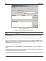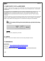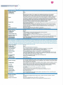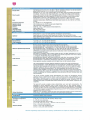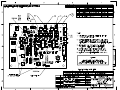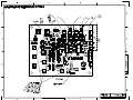
1
523-0038-010 TECHNICAL MANUAL OPERATION AND MAINTENANCE INSTRUCTIONS 09G090 TYPE 800I HD IMPORTER (P/N 200396-1 and 200396-2) (214) 381-7161 COPYRIGHTED 8 2009 BY CONTINENTAL ELECTRONICS 4212 S. BUCKNER BLVD. DALLAS, TEXAS 75227 www.contelec.com FAX: (214) 381-4949 ISSUED - 16 DECEMBER 2009 800I PREFACE This Operation and Maintenance manual gives the physical and functional description, installation, operation, theory of operation, maintenance, parts lists, and diagrams for the identified equipment. Operator and service personnel should become familiar with the manual contents before attempting to install, operate, or maintain the equipment. In addition to the Safety Summary which follows the Table of Contents, specific WARNINGS, CAUTIONS and NOTES are located throughout this manual where they apply. Continental Electronics (CE) manufactured this equipment to conform with current electrical, radiation, and safety codes of the United States to the extent that they apply. It is the user's responsibility to comply with all local and national codes during installation and operation of the equipment. CE reserves the right to make any changes, without notice, to this or any of CE's products to improve reliability, performance, function, or design. CE does not assume any liability resulting from the application or use of any product or circuit described herein; nor does CE convey any license under its patent rights or the rights of others. The information in this document has been carefully checked and is believed to be entirely reliable. While all reasonable efforts to ensure accuracy have been taken in the preparation of this manual, CE assumes no responsibility resulting from omissions or errors in this manual, or from the use of information contained herein. These instructions do not purport to cover all details or variations in equipment nor to provide for every possible contingency that might be met during installation, operation, or maintenance. Should further information be desired or should particular problems arise which are not covered sufficiently for the user's purpose, the matter should be referred to CE. All Rights Reserved This document contains proprietary information of Continental Electronics and shall not be duplicated, nor its contents used for any purpose, unless express written permission is obtained from Continental Electronics. CUSTOMER SERVICE Continental Electronics customer service is available for assistance at any time, 24 hours a day, weekends and holidays included. Call anytime day or night: Parts Services Engineering Services Main Offices Web Address (214) 388-3737 (214) 388-5800 (214) 381-7161 (8:00 am - 5:00 pm CT) www.contelec.com You may write to any of these services at 4212 S. Buckner Blvd., Dallas, Texas 75227-0879, or FAX (214) 381-4949. 800I INSERT LATEST CHANGE PAGES. DESTROY SUPERSEDED PAGES LIST OF EFFECTIVE PAGES NOTE: The portion of text affected by the changes is indicated by a change number located in the footer of each changed page. Dates of original and change pages are: Original...... 0 ...... 16 December 2009 TOTAL NUMBER OF PAGES IN THIS PUBLICATION IS 153 CONSISTING OF THE FOLLOWING: Page No. *Change Title................................................. Preface ............................................ A-Page ............................................ i - v.................................................. vi Blank........................................... vii - xi.............................................. xii Blank ......................................... 0 0 0 0 0 0 0 Page No. *Change 1-1 - 1-7.......................................... 1-8 Blank........................................ 2-1 - 2-7.......................................... 2-8 Blank........................................ 3-1 - 3-22........................................ 4-1 - 4-4.......................................... 5-1 - 5-4.......................................... 0 0 0 0 0 0 0 *Zero in this column indicates an original page. A Page No. *Change 6-1 - 6-8 .......................................... 4 B-Size Drawings.......................... 7-1 - 7-2 .......................................... 4 B-Size Drawings.......................... 8-1................................................... 8-2 Blank ........................................ 72 Vendor Pages............................. 0 0 0 0 0 0 0 800I Paragraph TABLE OF CONTENTS Title Page SECTION 1 - GENERAL INFORMATION 1-1. 1-1.1 1-1.2 1-1.3 1-1.4 1-1.5 1-1.6 1-1.7 1-1.8 1-2. 1-3. 1-3.1 1-3.2 1-3.3 1-4 Introduction ...........................................................................................................................................1-1 Section 1 - General Information. ...........................................................................................................1-1 Section 2 - Installation Instructions. ......................................................................................................1-1 Section 3 - Operating Instructions.........................................................................................................1-1 Section 4 - Theory of Operation............................................................................................................1-1 Section 5 - Maintenance Instructions. ...................................................................................................1-1 Section 6 - Parts Lists............................................................................................................................1-1 Section 7 - Diagrams. ............................................................................................................................1-1 Section 8 - Supplemental Data. .............................................................................................................1-1 Physical Description..............................................................................................................................1-1 Functional Description. .........................................................................................................................1-4 Digital Computer, A1 ............................................................................................................................1-4 PCI Audio CCA, A2..............................................................................................................................1-4 GPS Clock Distribution CCA, A3.........................................................................................................1-4 Performance Characteristics..................................................................................................................1-4 SECTION 2 - INSTALLATION 2-1. 2-2. 2-2.1 2-2.2 2-3. 2-3.1 2-3.2 2-4. 2-4.1 2-4.2 2-4.2.1 2-4.2.2 2-4.2.3 2-4.2.4 2-4.2.5 2-4.3 2-4.3.1 2-4.3.2 2-4.3.3 2-5 2-5.1 2-5.2 2-6. Introduction ...........................................................................................................................................2-1 Unpacking And Inspection....................................................................................................................2-1 Domestic Shipments..............................................................................................................................2-1 International Shipments.........................................................................................................................2-1 Internal Options.....................................................................................................................................2-1 AC Power. .............................................................................................................................................2-1 Sample Rate Conversion .......................................................................................................................2-1 Installation.............................................................................................................................................2-3 Rack Mounting......................................................................................................................................2-3 Input Connections. ................................................................................................................................2-3 AC Power ..............................................................................................................................................2-3 Digital Inputs.........................................................................................................................................2-3 GPS Input. .............................................................................................................................................2-3 Analog Inputs. .......................................................................................................................................2-3 Motherboard Inputs. ..............................................................................................................................2-3 Output Connections...............................................................................................................................2-3 Digital Output........................................................................................................................................2-3 Motherboard Outputs. ...........................................................................................................................2-3 Front Panel Outputs...............................................................................................................................2-3 Initial Operation. ...................................................................................................................................2-6 Turn Importer On ..................................................................................................................................2-6 Turn Importer Off..................................................................................................................................2-6 Intra-Unit Wiring...................................................................................................................................2-7 i TABLE OF CONTENTS Paragraph 800I Title Page SECTION 3 - OPERATION 3-1. 3-2. 3-2.1 3-2.2 3-3. 3-3.1 3-3.2 3-3.2.1 3-4 3-5. 3-6. General ................................................................................................................................................. 3-1 Controls and Indicators......................................................................................................................... 3-1 Front Panel ........................................................................................................................................... 3-1 Rear Panel............................................................................................................................................. 3-1 Operating Procedures ........................................................................................................................... 3-1 User Interface ....................................................................................................................................... 3-1 Operation Screens................................................................................................................................. 3-1 Main Screen.......................................................................................................................................... 3-1 Normal Turn-On. ................................................................................................................................ 3-22 Normal Turn-Off ................................................................................................................................ 3-22 Emergency Turn-Off .......................................................................................................................... 3-22 SECTION 4 - THEORY 4-1 4-2 4-2.1 4-2.2 4-2.3 4-3 4-3.1 Introduction. ......................................................................................................................................... 4-1 Functional Description. ........................................................................................................................ 4-1 Digital Computer, A1. .......................................................................................................................... 4-1 PCI Audio CCA A2.............................................................................................................................. 4-1 GPS Clock Distribution CCA, A3 ........................................................................................................ 4-1 Detailed Circuit Descriptions. .............................................................................................................. 4-1 GPS Clock Distribution CCA, A3. ....................................................................................................... 4-1 SECTION 5 - MAINTENANCE 5-1. 5-2. 5-3. 5-3.1 5-3.2 5-3.3 5-3.4 5-4. 5-5. 5-6. 5-7 5-7.1 5-7.2 5-7.3 5-8 ii Routine Maintenance............................................................................................................................ 5-1 Maintenance Concept ........................................................................................................................... 5-1 Electrostatic Handling .......................................................................................................................... 5-1 General. ................................................................................................................................................ 5-1 Implementation..................................................................................................................................... 5-2 Grounding............................................................................................................................................. 5-2 Summary............................................................................................................................................... 5-3 Cleaning................................................................................................................................................ 5-3 Inspection ............................................................................................................................................. 5-3 Troubleshooting.................................................................................................................................... 5-3 Replacement Procedures....................................................................................................................... 5-3 Replace Digital Computer A1 Components.......................................................................................... 5-3 Replace PCI Audio CCA, A2 ............................................................................................................... 5-4 Replace GPS Clock Distribution CCA, A3 .......................................................................................... 5-4 Adjustments.......................................................................................................................................... 5-4 800I Paragraph TABLE OF CONTENTS Title Page SECTION 6 - PARTS LIST 6-1 6-2 6-3 6-4 6-5 6-6 6-7 6-8 Introduction ...........................................................................................................................................6-1 Index of Parts List .................................................................................................................................6-1 Reference Designations (Ref Des) ........................................................................................................6-1 Quantity.................................................................................................................................................6-1 CAGE Code ..........................................................................................................................................6-1 Part Number ..........................................................................................................................................6-1 Description ............................................................................................................................................6-1 Illustrations............................................................................................................................................6-1 SECTION 7 - DIAGRAMS 7-1 Introduction ...........................................................................................................................................7-1 SECTION 8 – SUPPLEMENTAL DATA 8-1 8-2 Introduction ...........................................................................................................................................8-1 Site Specific Equipment Configuration .................................................................................................8-1 iii TABLE OF CONTENTS 800I LIST OF ILLUSTRATIONS Figure Title Page SECTION 1 - GENERAL DESCRIPTION 1-1. 1-2. 1-3. Type 800I HD Importer ........................................................................................................................ 1-2 Importer Simplified Block Diagram. .................................................................................................... 1-5 Assembly Locator Diagram. ................................................................................................................. 1-6 SECTION 2 - INSTALLATION 2-1. 2-2. Importer Outline and Installation Drawing........................................................................................... 2-2 Front/Rear Panel Connector Location Diagram.................................................................................... 2-4 SECTION 3 - OPERATION 3-1. 3-2. 3-3. 3-4. 3-5. 3-6. 3-7. 3-8. 3-9. 3-10. 3-11. 3-12. 3-13a. 3-13b. 3-14a. 3-14b. 3-14c. 3-15. Importer Front/Rear Panels................................................................................................................... 3-2 Importer Control Panel Screen ............................................................................................................. 3-4 Importer Setup Screen .......................................................................................................................... 3-5 Log Service Setup Screen..................................................................................................................... 3-7 Link Status Screen ................................................................................................................................ 3-9 Digital Capture Client Screen............................................................................................................. 3-10 Data Client Screen.............................................................................................................................. 3-11 Web Admin Screen............................................................................................................................. 3-12 Exporter Configuration Screen ........................................................................................................... 3-13 Importer Configuration Screen ........................................................................................................... 3-14 Importer Monitor Screen .................................................................................................................... 3-15 Admin - Service Provider Screen ....................................................................................................... 3-16 Admin - Services Screen .................................................................................................................... 3-17 Admin - Services Screen .................................................................................................................... 3-17 Admin - Configuration Screen............................................................................................................ 3-19 Admin - Configuration Screen............................................................................................................ 3-19 Admin - Configuration Screen............................................................................................................ 3-20 Client Configuration Screen ............................................................................................................... 3-21 SECTION 4 - THEORY OF OPERATION 4-1. 4-2. iv Importer Simplified Block Diagram ..................................................................................................... 4-2 Assembly Locator Diagram.................................................................................................................. 4-3 800I TABLE OF CONTENTS LIST OF TABLES Table Title Page SECTION 1 - GENERAL DESCRIPTION 1-1 1-2 List of Major Equipment Supplied. .......................................................................................................1-3 Technical Characteristics. .....................................................................................................................1-7 SECTION 2 - INSTALLATION 2-1 2-2 2-3 Front/Rear Panel Connectors.................................................................................................................2-5 Importer Jumper Configuration Data.....................................................................................................2-6 Index of Wiring Lists ............................................................................................................................2-7 SECTION 3 – OPERATION 3-1 3-2 3-3 3-4 3-5 3-6 3-7 3-8 3-9 3-10 3-11 3-12 3-13 3-14 3-15 Front/Rear Panel Controls and Indicators .............................................................................................3-3 Importer Control Panel Screen Controls and Indicators ........................................................................3-4 Importer Setup Screen Controls and Indicators.....................................................................................3-5 Log Service Setup Screen Controls and Indicators ...............................................................................3-7 Link Status Screen Controls and Indicators ..........................................................................................3-9 Digital Capture Client Screen Controls and Indicators .......................................................................3-10 Data Client Screen Controls and Indicators ........................................................................................3-11 Web Admin Screen Controls and Indicators .......................................................................................3-12 Exporter Configuration Screen Controls and Indicators......................................................................3-13 Importer Configuration Screen Controls and Indicators......................................................................3-14 Importer Monitor Screen Controls and Indicators...............................................................................3-15 Admin - Service Provider Screen Controls and Indicators ..................................................................3-16 Admin - Services Screen Controls and Indicators ...............................................................................3-18 Admin - Configuration Screen Controls and Indicators ......................................................................3-20 Client Configuration Screen Controls and Indicators..........................................................................3-21 SECTION 5 - MAINTENANCE 5-1 Internal Assembly LED Indicators ........................................................................................................5-3 SECTION 6 - PARTS LISTS 6-1 6-2 Index of Parts Lists in Ref. Des. Order .................................................................................................6-1 Index of Parts Lists in Numerical Order................................................................................................6-1 SECTION 7 - DIAGRAMS 7-1 7-2 Index of Diagrams in Ref. Des. Order...................................................................................................7-1 Index of Diagrams in Numerical Order .................................................................................................7-1 SECTION 8 – SUPPLEMENTAL DATA 8-1 Index of Vendor Data Items ..................................................................................................................8-1 v TABLE OF CONTENTS 800I (This Page Intentionally Left Blank) vi 800I SAFETY SUMMARY SAFETY INFORMATION I This safety summary is intended for trained and qualified personnel who are aware of the dangers inherent in handling potentially hazardous electrical circuits. It is not intended as a complete or authoritative medical treatment course, but should serve as a reminder of accepted emergency techniques. The equipment documentation must be reviewed for familiarization with safety markings and instructions before operation or maintenance activities are attempted. Know where and how to turn off main electrical power to the equipment. User personnel should have training in first aid and cardiopulmonary resuscitation (CPR) techniques. Emergency medical, fire, and ambulance telephone numbers should be posted in clear view adjacent to each telephone. Make a note if 911 service is available. II USE CAUTION WHEN PLACING FINGERS IN VICTIM'S MOUTH, MUSCLE SPASMS CAN CAUSE THE MOUTH TO CLOSE WITH FORCE SUFFICIENT TO SEVER YOUR FINGERS. FAILURE TO COMPLY MAY RESULT IN LOSS OF FINGERS. a. ELECTRICAL SHOCK TREATMENT In case of an electrical shock the A-B-Cs of basic life support treatment may be used while medical assistance is being summoned. __________ WARNING HIGH VOLTAGE/RF HAZARD WHEN A VICTIM IS IN CONTACT WITH HIGH VOLTAGE OR RF, ENSURE SOURCE POTENTIAL IS REMOVED AND CIRCUIT GROUNDED BEFORE ATTEMPTING ARTIFICIAL RESPIRATION. FAILURE TO COMPLY MAY RESULT IN PERSONAL INJURY OR DEATH. 1. __________ WARNING BITE HAZARD GENERAL If the victim is not responsive follow the A-B-Cs of basic life support. Place victim face-up on a flat hard surface. Three critical areas (Airway, Breathing, and Circulation) need immediate attention: Airway - If victim is unconscious, open airway by lifting up the neck while pushing back on the victim's forehead. Refer to Figure 1A. Clear mouth of obstructions and observe for breathing. __________ WARNING RESCUER KEEP CALM EXCESSIVELY DEEP AND RAPID BREATHING BY THE RESCUER MAY RESULT IN RESCUER BECOMING FAINT, TO TINGLE, AND EVEN LOSE CONSCIOUSNESS. BREATHING SHOULD BE NORMAL IN RATE WITH ONLY MODERATE INCREASE IN VOLUME. FAILURE TO COMPLY MAY RESULT IN RESCUE BEING PREMATURELY STOPPED DUE TO FATIGUE. b. Breathing - If victim is not breathing begin artificial breathing. Tilt head, pinch nostrils, make airtight seal with your mouth, and blow 4 quick full breaths into the victim's lungs. Refer to Figure 1B. c. Circulation - If victim does not have a pulse, see Figure 1C, begin artificial circulation. Depress sternum 1½ to 2 inches then release. Refer to Figures 1D and 1E. WITH ONE rescuer: Perform 30 compressions and 2 quick breaths at the rate of 100 per minute. WITH TWO rescuers: Same as one rescuer except switch between rescuers about every 5 cycles or 2 minutes. vii SAFETY SUMMARY 800I Figure 1. Artificial Breathing and Circulation. 2. III If the victim is responsive treat for shock in the following way: a. Keep victim warm. b. Keep victim as quiet as possible. c. Loosen victim's clothing. d. Place victim in a reclining position if possible. FIRST-AID Users of this equipment are urged to become familiar with first-aid theory and practices. The following information is intended for reference only. It is important that all personnel using this equipment be prepared to give adequate Emergency First-Aid to fellow users. viii 1. In case of extensive electrical burns and broken skin: a. Cover area with clean sheet or cloth. (Cleanest available cloth article.) b. Do Not break blisters, remove tissue, remove adhered particles of clothing, or apply any salve or ointment. c. Treat victim for shock as follows: Keep victim warm, quiet, reclined, and loosen clothing. d. Arrange transportation to a hospital as quickly as possible. e. If arms or legs are affected keep them elevated. 800I III SAFETY SUMMARY FIRST-AID - Continued CAUTION NOTE The CAUTION sign as shown above, denotes an equipment hazard. It calls attention to an operating procedure, practice, or the like, which, if not correctly performed or adhered to, may result in damage to or destruction of part or all of the equipment. Do not proceed beyond a CAUTION sign until the indicated conditions are fully understood and met. If medical help will not be available within an hour and the victim is conscious and not vomiting, give him a weak solution of salt and soda: 1 level teaspoon of salt and 1/2 level teaspoon of baking soda to each quart of water (neither hot nor cold). Allow victim to sip slowly about 4 ounces (a half glass) over a period of 15 minutes. Discontinue fluid if vomiting occurs. (Do Not give alcohol.) V 2. IV In case of less severe electrical burns (1st. or 2nd. degree) with no broken skin: a. Apply cool (not ice cold) compresses using the cleanest available cloth article. b. Do Not break blisters, remove tissue, remove adhered particles of clothing, or apply any salve or ointment. c. Apply clean dry dressing if necessary. d. Treat victim for shock as follows: Keep victim warm, quiet, reclined, and loosen clothing. e. Arrange transportation to a hospital as quickly as possible. f. If arms or legs are affected keep them elevated. SAFETY SYMBOLS Safety symbols shown below are typical of those used in the operation and maintenance manual: Follow the safety precautions listed below in addition to any site safety precautions when servicing this equipment. Failure to observe these safety precautions may result in serious injury or death. __________ WARNING DEATH OR SERIOUS INJURY MAY RESULT IF PERSONNEL FAIL TO OBSERVE THE FOLLOWING SAFETY PRECAUTIONS. 1. Never work on electronic equipment unless there is another person present who is familiar with the operation and hazards of the equipment and who is competent in administering first aid. When the engineer or technician is aided by operators, he must warn them about dangerous areas. 2. Do not contact high voltage or current connections when power is applied to this equipment. 3. Whenever the nature of the procedure permits, keep one hand away from the equipment to reduce the hazard of current flowing through vital organs of the body. 4. Make sure that all rings, watches, necklaces, metallic ear-rings, and other similar items are removed before working with this equipment. __________ WARNING The WARNING sign as shown above, denotes a personal hazard. It calls attention to a procedure, practice, or the like, which, if not correctly performed or adhered to, may result in personal injury. Do not proceed beyond a WARNING sign until the indicated conditions are fully understood and met. SAFETY PRECAUTIONS ix SAFETY SUMMARY V SAFETY PRECAUTIONS - Continued 5. Whenever possible, the power supply to the equipment must be turned-off and tagged or locked before beginning work on the equipment. 6. Extremely high current, low voltage, dc is used in portions of the equipment. Do not be misled by the low voltage rating (5 to 30 V dc) of the current sources. Severe injury to personnel and damage to the equipment can occur if the voltage sources are shorted (directly connected) to ground or ground returns by tools or test equipment. VI VOLTAGE, CURRENT, and LIGHTNING HAZARDS 800I b. Ensure that radiation restrictions for nearby equipment or other high power rf radiation sources are observed before performing maintenance on this equipment. c. Prior to and during operation and maintenance, observe all radiation restrictions in effect at the site. d. If personnel are suspected or known to have been exposed to rf radiation in excess of rf radiation protection guidelines, consult medical personnel immediately. VIII TOXIC MATERIAL/ENVIRONMENTAL HAZARDS The voltage, current, and lightning hazards listed in 1 through 3 below exist for the equipment. For hazards associated with vendor equipment, refer to appropriate manuals furnished with the item. The hazards listed in 1 and 2 below may exist when performing maintenance of the equipment. For hazards associated with vendor equipment, refer to appropriate manuals furnished with the item. 1. The dc voltage hazards consist of potentials of 5 V dc to 250 V dc between power supply lines within the equipment. 1. 2. High voltage, high current, 50/60 Hz ac power is supplied to the equipment. 3. Antenna systems acting as an attracting device present a lightning hazard to personnel performing maintenance on the equipment. No maintenance should be performed on the unit when thunderstorms are imminent or in progress, while the antenna is connected. Toxic or flammable solvents and corrosive chemicals used in cleaning operations may involve the use of caustic or acid solutions, skin irritants, and organic solvents that are flammable and/or toxic. The following precautions, as a minimum, must be observed by personnel using such materials. a. Work only in well ventilated areas. b. Wear organic vapor respirators when using organic solvents or corrosive chemicals. c. Wear chemical safety goggles, gloves and aprons when using corrosive chemicals. VII RF RADIATION HAZARDS d. The rf radiation hazards listed in 1 and 2 below exist for the equipment. For hazards associated with vendor equipment, refer to appropriate manuals furnished with the item. Do not use flammable chemicals near or inside the equipment while power is applied to the system. e. Maintain a fully stocked first aid cabinet nearby for emergency treatment of scalds, burns, etc. f. Flush away coolant or cleaning solvent contamination from any part of the body. 1. 2. RF radiation from the equipment could present a potential hazard to personnel wearing cardiac pacemakers. The following rf radiation hazard precautions shall be observed when operating or performing maintenance on the equipment: a. x Proper precautions shall be taken to protect cardiac pacemaker users. 2. Benzene, Carbon Tetrachloride, Freon, and Trichloroethane based Solvents should only be used in well ventilated areas. The fumes are toxic and may be hazardous to your health or can cause death by suffocation. 800I IX SAFETY SUMMARY MAJOR EMPLACEMENT AND MAINTENANCE HAZARDS 2. The precautions given in 1 and 2 below must be observed to prevent injury or death to personnel: 1. Installation and assembly hazards associated with the equipment are as follows: a. b. 2. X After performing maintenance ensure the doors and covers are installed prior to attempting to return the equipment to service. On all electrolytic capacitors, make sure terminal polarity markings [positive (+) and negative (-)] are observed when connecting capacitors to + dc buses. a. Table tops or work areas should be covered with grounded conductive tops. Test areas should have conductive floor mats. b. Tools and test equipment used in protected work areas shall be properly grounded. Ensure that soldering-iron tips are grounded. If plastic handled tools must be used, they shall be treated with a topical antistat. c. Devices, or circuit cards with devices, should not be inserted into or removed from circuits with the power on because transient voltages may cause permanent damage. d. Use a conductive wrist strap when removing a circuit card containing MOS/CMOS devices from a card cage or when removing a device from a circuit card. e. The devices are to be stored or transported in static shielding bags, anti-static rails, or conductive foam. While performing maintenance on the equipment, observe the following precautions: a. Maintenance of equipment shall not be performed when thunderstorms and lightning are imminent or in progress. b. When performing maintenance on the equipment make sure all ac power to the unit is removed. STATIC SENSITIVE DEVICES There are some circuits throughout the equipment using metal-oxide-semiconductor (MOS) and complementary MOS (CMOS) integrated circuits. This requires stringent attention to handling techniques due to the sensitivity to static electricity. The following paragraphs outline the procedures to use when handling MOS or CMOS devices. 1. Electrostatic handling of MOS devices is of prime importance. Static electricity is always present in any work environment. It is generated when ever two different materials are rubbed together. A person walking across the floor can generate a charge of thousands of volts. A person working at a bench, sliding around on a stool, or rubbing his arms on the work bench can develop a high static potential. For preventing damage to devices due to ESD, use the following precautions: Electrostatic discharge hazards in MOS/CMOS devices are prevalent. Such damage can be produced by Electrostatic Discharge (ESD) due to improper handling or installation. All MOS/CMOS devices are susceptible to damage by the discharge of electrostatic energy between any two pins. This sensitivity to static charge is due to the fact that gate input capacitance (5 picofarads typical) in parallel with an extremely high input resistance (1012 ohms typical) lends itself to a high input impedance and hence readily builds up the electrostatic charges. 3. ESD grounding is critical to safe handling of ESD sensitive devices. Earth ground rods for ESD protection shall be solid copper or copper jacketed steel and shall be driven six to eight feet into the earth beyond the work area floor slab with approximately six inches exposed for making connection. Dry soil conditions may require a copper sulfate drip. Electrical grounds shall be isolated from static grounds. Water pipes offer convenient grounds; however, they may not be connected to earth ground. These techniques are for minimizing the difference of potential between separate grounds, and not for reducing the ohmic resistance to earth. xi SAFETY SUMMARY 800I (This Page Intentionally Left Blank) xii 800I GENERAL INFORMATION SECTION 1 – GENERAL INFORMATION 1-1. INTRODUCTION 1-1.3 Section 3 - Operating Instructions. This Technical Manual contains instructions for installation, operation and maintenance of Continental Electronics Type 800I HD Importer. The Technical Manual is divided into the following sections: This section contains a description of controls and indicators, turn-on procedure, operating procedure, shutdown procedure, and emergency shutdown procedure. 1-1.4 Section 4 - Theory of Operation. Section 1 - General Description Section 2 - Installation Instructions Section 3 - Operating Instructions Section 4 - Theory of Operation Section 5 - Maintenance Instructions Section 6 - Parts List Section 7 - Diagrams Section 8 - Supplemental Data A table of contents is provided at the front for the manual, indicating the page number for the start of each topic. The following paragraphs describe the contents of each section of the transmitter Operation and Maintenance Manual. 1-1.1 Section 1 - General Information. This section contains a physical and functional description of the Exporter and its major subassemblies. Also included in Section 1 is a List of Equipment Supplied (Table 1-1), List of Optional Recommended Equipment (Table 1-2), and List of Characteristics (Table 1-3). This section includes general functional theory and detailed theory of operation for the Exciter and its subassemblies. 1-1.5 Section 5 - Maintenance Instructions. This section includes preventive and corrective maintenance procedures for the Exporter along with instructions for troubleshooting, and remove and replace procedures. Alignment and performance checks are included as appropriate. 1-1.6 Section 6 - Parts Lists. This section includes electrical parts lists for the assemblies as shown in Table 6-1 and the Assembly Diagrams as shown in Table 6-2. 1-1.7 Section 7 - Diagrams. This section includes schematic as listed in Tables 7-1 and 7-2. 1-1.2 Section 2 - Installation Instructions. 1-1.8 Section 8 - Supplemental Data. This section contains instructions to be followed while unpacking, staging and installing the Exporter, interface with the input/output connections of the Exporter, optional configurations and initial adjustments where required. Existing wiring lists are included at the end of Section 2 for site level wiring. Also included are steps necessary to prepare the Exporter for initial turn-on. This section includes vendor data sheets and manuals as identified in Table 8-1. 1-2. PHYSICAL DESCRIPTION The Importer is a standard 19-inch rack mounted assembly, requiring 2RU (3½-inch) panel space. Refer to Figure 1-1 for a view of the Importer. For complete technical specifications refer to Table 1-2. A list of all major subassemblies, in reference designator order, is provided in Table 1-1. 1-1 GENERAL INFORMATION 800I 09G090A Figure 1-1. Type 800I HD Importer. 1-2 800I GENERAL INFORMATION Table 1-1. List of Major Equipment Supplied. Ref. Des. Description Part No. – HD Importer, 800I 200396-1 200396-2 A1 A2 (-1 only) A2 (-2 only) A3 (-2 only) Digital Computer CCA, PCI Audio (Orban Optimod-PC 1101) CCA, PCI Audio (ASI 5111) CCA, GPS Clock Distribution 109-0695-310 270-3359-020 270-3359-040 202223-1 1-3 GENERAL INFORMATION 1-3. FUNCTIONAL DESCRIPTION The Importer adds supplemental audio/data, advanced applications services (AAS), and program-associated data (PAD) to the primary HD programming service. In addition, the Importer manages content and delivery from other service providers and supports iTunes Tagging. The Importer interfaces directly to the Continental 800EXP Exporter. A functional description is provided for the assemblies shown in Table 1-1, List of Major Equipment Supplied. For a list of acronyms and abbreviations refer to Table 1-3. Refer to Figures 1-2 and 1-3 during the functional description. The functional relationship of each of these units is shown in Figure 1-2, a simplified block diagram of the Importer. 1-3.1 Digital Computer, A1. The Digital Computer controls and monitors overall Importer operation. The CPU multiplexes all of the service provider data, multicast audio and data streams, and outputs it through one of the rear panel LAN ports. The computer is a rack mounted PC and uses the Microsoft Windows XP Pro operating system. Access to the user interface is with mouse, keyboard and monitor connectors on the back panel (or through another PC connected over the LAN). 1-4 800I The Importer also includes a DVD-RW drive, PCI Audio CCA, GPS Clock Distribution CCA (-2 version only) and a PCI Express slot for expansion. The Importer application software is supplied by Ibiquity. 1-3.2 PCI Audio CCA, A2. The -1 version uses an Orban 1101 audio card. The -2 version uses an ASI 5111 audio card. The audio card provides a variety of analog and digital inputs/outputs and other features depending on which card is used. The audio card mixes all analog, digital and Wave inputs, and routes the multiplexed stream to the motherboard for output to the LAN. 1-3.3 GPS Clock Distribution CCA, A3. The GPS CCA provides GPS-synchronized 44.1kHz sample rate conversion for the -2 digital input. The digital output is routed to the 5111 audio card. The GPS CCA is used only with the -2 version. 1-4 PERFORMANCE CHARACTERISTICS. Table 1-2 contains the electrical, mechanical, and environmental specifications for the 800I HD Importer. 800I GENERAL INFORMATION A2 MIC INPUT (-2 ONLY) 1 ANALOG INPUT(S) ANALOG OUTPUT(S) 1 2 1 10 MHZ AES INPUT(S) 1 1 DIGITAL OUTPUT(S) PCI AUDIO CCA GPS CLOCK 1 DISTRIBUTION AES INPUT(S) CCA PCI P/O A1 BUS LAN MOTHERBOARD SUPPLEMENTAL/ AAS/PAD OUT 09G093 P/O A1 +5 VDC 2 A3 (-2 ONLY) COMPUTER POWER SUPPLY 1 - THE AVAILABLE AUDIO CARDS OFFER DIFFERENT FEATURES. THE NUMBER OF ANALOG, DIGITAL AND OTHER INPUTS AND OUTPUTS IS DEPENDENT ON WHICH AUDIO CARD IS USED. 2 - THE EXTERNAL 10 MHZ REFERENCE AND GPS CLOCK CCA A3 ARE REQUIRED ONLY FOR THE -2 VERSION USING THE ASI5111 AUDIO CARD. THE ORBAN 1101 AUDIO CARD (-1 VERSION) MAY USE AN EXTERNAL OR AN ON-BOARD 10 MHZ SOURCE. Figure 1-2. Importer Simplified Block Diagram. 1-5 GENERAL INFORMATION 800I PCI AUDIO CCA A2 THESE CABLES ARE USED ONLY ON THE -2 VERSION GPS CLOCK DISTRIBUTION CCA A3 (-2 ONLY) DIGITAL COMPUTER A1 09G092 Figure 1-3. Assembly Locator Diagram. 1-6 800I GENERAL INFORMATION Table 1-2. Technical Characteristics. Characteristic Performance Electrical Input Power: 100-240 Vac; 47-63 Hz; universal voltage input; no voltage range switching required. Mechanical Size: 16.79 inches (426.7 mm) wide centered on a 19 inch wide (482.6 mm) rackmounted panel; 3.46 inches (87.88 mm) high; 18.9 inches (480.1 mm) deep. Weight: Approx. 24 lbs. (10.9 kg). Environmental Temperature Range: +32 to +104 degrees F (0 to +40 degrees C), operating. Relative Humidity Range: _______________________ 10 to 85% at +104 degrees F (+40 degrees C), non-condensing. For PCI audio card specifications, refer to datasheet or user manual in Section 8, Supplemental Data or included in the shipment. 1-7 GENERAL INFORMATION 800I (This Page Intentionally Left Blank) 1-8 800I INSTALLATION SECTION 2 - INSTALLATION 2-1. INTRODUCTION 2-2.2 International Shipments. This section will guide the user in the unpacking, inspection, selection of internal options, and installation of the 800I HD Importer. Refer to Figure 2-1 for chassis dimensions. The Importer international shipping installation instructions are identical to those for domestic shipment. Refer to instructions in Paragraph 2-2.1 for unpacking and inspection. 2-2. UNPACKING AND INSPECTION 2-3. INTERNAL OPTIONS 2-2.1 Domestic Shipments. Remove the Importer from its shipping crate and packing material. Remove top cover from the Importer by removing the retaining screws. Prior to installing the Importer, examine the following paragraphs to ensure the internal options are set for the desired configuration. 2-3.1 AC Power. Inspect the equipment for loose screws and fasteners. Ensure that circuit cards are properly installed, and cable and wiring connections are tight. Replace top cover and tighten fasteners when inspection is complete. If any item is damaged in transit, note the damage on the shipping documents and immediately file a freight claim. All boxes and packing material should be retained for the freight inspector. When the Importer is shipped as a stand-alone item, perform the items outlined in the following paragraphs. The Importer contains a universal power supply that operates on any voltage from 100 - 240 VAC. No switches or jumpers are needed to accommodate this input range. 2-3.2 Sample Rate Conversion. The -2 Importer is shipped from the factory with digital audio sample rate conversion on GPS Clock Distribution CCA A3 enabled. If the setting needs to be changed, refer to Table 2-2 for a description of the settings. CCA A3 is not used on the -1 version. When the Importer is shipped as an integral part of a transmitter, the fuse rating, rack mounting, and appropriate internal options are selected at the factory. The user should skip ahead to Input Connections, paragraph 2-4.2. 2-1 INSTALLATION 800I AIR EXHAUST AIR EXHAUST 18.90 IN. (48 CM) 09G096 3.46 IN. (8.8 CM) 18.98 IN. (48.2 CM) Figure 2-1. Importer Outline and Installation Drawing. 2-2 800I INSTALLATION 2-4. INSTALLATION Perform the instructions in the following paragraphs to install the Importer in the equipment rack and make the necessary interface connections. __________ WARNING HIGH VOLTAGE HAZARD ENSURE AC POWER IS REMOVED FROM THE IMPORTER BEFORE SERVICING. FAILURE TO COMPLY MAY RESULT IN DEATH OR INJURY TO PERSONNEL. 2-4.1 Rack Mounting. The Importer requires 2U (3.5 in.) of vertical space. Install the Importer into a standard 19-inch rack using the included slide assembly. Connector AES2 (W4J2) is not used. The -2 input is routed to GPS/Clock Distribution CCA A3 for 44.1 kHz fixed-rate sampling. 2-4.2.3 GPS Input. For the -1 version, the BNC connector located on the “octopus” cable or rear panel provide for the optional external 10 MHz clock input. The external clock, if used, is routed to the 1101 audio card. For the -2 version, an SMA connector (W3J3) provides for the required external 10 MHz clock input. This clock signal is routed to GPS/Clock Distribution CCA A3. 2-4.2.4 Analog Inputs. For the -1 version, the two left and right channel inputs are via the “octopus” cable. For the -2 version, the two left and right channel inputs are via a DB-9 connector. The analog inputs are multiplexed with the digital inputs and routed to the motherboard for output on the LAN. 2-4.2.5 Motherboard Inputs. The motherboard offers rear panel inputs for the following: 2-4.2 Input Connections. For the -1 version only, connect the supplied “octopus” cable (eight XLR connectors, one BNC connector and one DB-25 connector) to the rear panel DB-25 connector. The following paragraphs outline connections made to the Importer from external power and signal sources. Refer to Figure 2-2 and Table 2-1 for a summary of all front/rear panel connections. NOTE It is highly recommended that the Importer be connected to an uninterruptible power supply (UPS) with surge protection to maintain operation during power outages and provide protection against voltage spikes. 2-4.2.1 AC Power. Mains power is applied to the port labeled AC INPUT. The voltage applied to this connector should be in the range of 100 to 240 VAC at a frequency of 47 to 63 Hz. No switches or jumpers are needed to accommodate this input range. Connect the power cord female end to the AC INPUT connector on the rear of the Importer. Plug the male connector end into a compatible power source (refer to Figure 2-3). Also, see Paragraph 23.1. 2-4.2.2 Digital Inputs. For the -1 version, the two digital inputs are via the “octopus” cable. The -1 inputs are routed to the 1101 audio card for 44.1 kHz fixed-rate sampling. For the -2 version, the one digital input is via XLR connector AES1 (W4J1). 1. 2. 3. 4. 5. Mouse (PS/2; green) Keyboard (PS/2; purple) Two LAN ports (RJ-45) for Importer control Microphone (⅛-inch TRS; pink) Line In (⅛-inch TRS; light blue; for audio sources) 2-4.3 Output Connections. The following paragraphs outline connections made from the Importer to external equipment. Refer to Figure 2-2 and Table 2-1 for a summary of all front/rear panel connections. 2-4.3.1 Digital Output. For the -1 version, the two digital outputs are via the “octopus” cable. For the -2 version, the one digital output is via XLR connector AES1 OUTPUT (W5J3). These are not the main Importer audio/data outputs. These connectors are used only to monitor the audio card’s digital output. The main output is via one of the two LAN ports. 2-4.3.2 Motherboard Outputs. The motherboard offers rear panel outputs for the following: 1. 2. 3. 4. 5. 6. Line Out (⅛-inch TRS; lime; for headphone/speaker) COM1 (DB-9; for serial devices) VGA (DB-15; for monitor) LPT1 (DB-25; for parallel devices) LAN port (RJ-45) for main Importer audio/data output USB 2.0 ports (type A; for host control functions) 2-4.3.3 Front Panel Outputs. The front panel offers two USB 2.0 ports (type A; for host control functions). 2-3 INSTALLATION 800I SYSTEM RESET POWER ALARM RESET 1 2 Manufactured under license from iBiquity Digital Corp. U.S. and Foreign Patents. The HD Radio logo is a proprietary trademark of iBiquity. iBiquity Digital software © 2000-2008 iBiquity Digital Corporation. All rights reserved. ` -1 VERSION 3 5 6 9 8 7 4 10 Manufactured under license from iBiquity Digital Corp. U.S. and Foreign Patents. The HD Radio logo is a proprietary trademark of iBiquity. iBiquity Digital software © 2000-2008 iBiquity Digital Corporation. All rights reserved. 09G097 -2 VERSION 21 20 19 11 18 17 16 15 14 12 13 Figure 2-2. Front/Rear Panel Connector Location Diagram. 2-4 800I INSTALLATION Table 2-1. Front/Rear Panel Connectors. Index No. Connector Function 1 USB 2.0 ports Type A, for connection to function as a host to peripheral devices. 2 Keyboard port PS/2, for connection to a keyboard. 3 10 MHz input (-1 only) BNC, for 10 MHz GPS reference clock signal input. 4 Signal input/output (-1 only) DB-25, for all analog/digital (AES/EBU) input/output and 10 MHz GPS reference clock signal input. 5 AC power input AC power input connector. Remove the attached ac power cord from its receptacle to turn the Importer off. 6 Mouse port (Green) PS/2, for connection to a mouse. 7 Parallel connector DB-25, for connection to a parallel printer, scanner, or other devices. 8 LAN ports RJ-45, for Importer control and multiplexed audio and data input/output. 9 Analog input/output (-2 only) A2J2, DB-9, for balanced mono/stereo analog input and output. 10 10 MHz input (-2 only) W3J3, SMA, for 10 MHz GPS reference clock signal input. 11 Microphone input (-2 only) A2J3, ¼-inch TRS, for connection to a microphone. 12 AES output (-2 only) W5J3, XLR, for HD AES/EBU digital audio output. 13 AES1 input (-2 only) W4J1, XLR, for HD AES/EBU digital audio input (channel 1). 14 AES2 input (-2 only) W4J2, XLR, for HD AES/EBU digital audio input (channel 2). 15 Microphone port (Pink) ⅛-inch TRS, for connection to a microphone. 16 Line Out port (Lime) ⅛-inch TRS, for connection to a headphone or speaker. 17 Line In port (Light Blue) ⅛-inch TRS, for connection to a tape, CD, DVD player, or other audio sources. 18 USB 2.0 ports Type A, for connection to function as a host to peripheral devices. 19 VGA connector DB-15, for connection to a VGA monitor. 20 Serial connector DB-9, COM1, for connection to serial devices. 21 Keyboard port (Purple) PS/2, for connection to a keyboard. 2-5 INSTALLATION 800I 2-5 INITIAL OPERATION. 3. Press momentary POWER switch located behind front panel access door. The following information will guide the user in operation of the Importer. 4. Wait for the Importer to boot. When the Importer finishes its internal self-test, the front panel LEDs show the operational status of the Importer. 2-5.1 Turn Importer On. Place the Importer in operation and turn it on using the following steps: 1. 2. Confirm that all connections and options have been correctly selected as outlined in the previous paragraphs. Connect the Importer power cable to a power source by plugging it into an ac power outlet. 2-5.2 Turn Importer Off. 1. Perform system shutdown via the desktop Start button or 2. Press momentary POWER switch located behind front panel access door. The Importer can be left on at all times if there is no reason to remove AC power. There are no items internal to the Importer, such as crystal ovens, that require standby power. Table 2-2. Importer Jumper Configuration Data. Jumper Pin to Pin Function GPS Clock Distribution CCA - A3 (202223-1)(-2 version only) J1-J2 *1-2 2-3 Enables digital audio sample rate conversion at U5 for AES input No.1 (channel 1). Disables digital audio sample rate conversion at U5 for AES input No.1 (channel 1). J3-J4 *1-2 2-3 Enables digital audio sample rate conversion at U6 for AES input No.2 (channel 2). Disables digital audio sample rate conversion at U6 for AES input No.2 (channel 2). ________________________________ Note: (*) is the default jumper setting. 2-6 800I INSTALLATION 2-6. INTRA-UNIT WIRING A wiring list is provided for the -2 version to facilitate reconnection of loose cabling/wiring and for troubleshooting purposes. Intra-unit wiring is defined as wiring within a single unit. This wiring list is identified in Table 2-10 followed by the wiring list. Table 2-3. Index of Wiring Lists. Wire List No. Rev. Description WL200396-2 1 Importer, 800I INTRA-UNIT WIRING LIST WIRELIST NO: 200396-2 800I IMPORTER, ASI5111, CEC SRC ECN NO: ASSY NO: 200396-2 PL NO: 200396-2 SCHEMATIC: 200397 WIRE NO WIRE SIZE DATE: 29 OCTOBER 2009 REV: 1 REVISED: WIRE LENGTH FROM TO REMARKS W1 W1 W1 W1P1 W1P2 W1J1 A3J7 A3J8 REAR PANEL BRACKET CHANNEL 1 IN CHANNEL 2 IN W2 W2 W2 W2P1 W2P2 W2J2 A3J10 A3J11 REAR PANEL BRACKET CHANNEL 1 OUT CHANNEL 2 OUT W3 W3 W3P1 W3J3 A3J9 REAR PANEL BRACKET 10MHZ IN TO SRC 10MHZ FROM EXPORTER W4 DO NOT INSTALL, SHIPS WITH UNIT AES CHANNEL 1 INPUT FROM CUSTOMER W5 W5P2 W2J2 (REAR PANEL) W5P1 W5J3 A2J1 CHANNEL 1 AND 2 OUT TO AUDIO CARD LOCKED AUDIO WAV AUDIO OUTPUT 2-7 INSTALLATION 800I (This Page Intentionally Left Blank) 2-8 800I OPERATION SECTION 3 - OPERATION 3-1. GENERAL This section of the Operation and Maintenance Manual describes the 800I HD Importer controls and indicators, and initial operation and shutdown of the unit. 3-2. CONTROLS AND INDICATORS Control, metering and status indication is accomplished through the use of Web browser screens, and front and rear panel controls and indicators. The Main browser screen, Figure 3-2, is displayed upon a successful Internet connection to the Importer. Screen navigation is accomplished using a mouse or touchpad. Select the screen tab at the bottom of each screen to display the desired screen. Panel indications include 16 front panel LEDs, and 2 rear panel LAN port link and activity LEDs. Two pushbuttons, Reset and Diag(nostics), are located on the rear panel. 4. 5. 6. 7. 8. 9. 10. 11. 12. 13. 14. 15. 16. 17. DB-9 COM1 connector for serial devices DB-15 connector for VGA monitor Dual RJ-45 LAN ports Four Type A USB 2.0 ports ⅛-inch TRS Line In jack ⅛-inch TRS Line Out jack ⅛-inch TRS microphone jack ¼-inch TRS microphone jack SMA connector for 10MHz GPS reference clock signal input (-2 only) DB-9 connector for balanced stereo analog output (-2 only) Two XLR connectors for HD AES/EBU digital audio input (AES1 and AES2) (-2 only) One XLR connector for HD AES/EBU digital audio output (-2 only) DB-25 connector for connection of an included “octopus” cable that provides analog/digital input/output and external clock input (-1 only) BNC connector for external clock input (-1 only) 3-3. OPERATING PROCEDURES Refer to Figure 3-1 and Table 3-1 for a description of the operating controls and indicators found on the front and rear panels of the Importer. Figure 3-1 shows the front and rear panel controls and indicators. Table 3-1 identifies the function of each control and indicator. Refer to Figures 3-2 thru 3-15 and Tables 3-2 thru 3-15 for a description of the operating controls and indicators found on the browser screens. Figures 3-2 thru 3-15 show the screen. Tables 3-2 thru 3-15 identify the function of each control and indicator. 3-2.1 Front Panel. The front panel has the following controls, indicators and connectors, from left to right: 1. 2. 3. 4. 5. 6. 7. 8. POWER LED indicator HDD LED indicator TEMP LED indicator FAN LED Indicator Two Type A USB 2.0 ports SYSTEM RESET switch ALARM RESET switch Momentary POWER switch 3-2.2 Rear Panel. The rear panel has the following controls, indicators and connections, from left to right: 1. 2. 3. AC power input (100-240 volts, 47-63 Hz) Dual PS/2 connectors for keyboard and mouse DB-25 connector for parallel devices 3-3.1 User Interface. The user interface consists of 17 primary screens displayed on a remote computer using an Internet connection and a Web browser. 3-3.2 Operation Screens. The Importer contains a graphical user interface (GUI) that is accessed over a LAN connection. It is designed to be simple to use and easy to navigate. The operator can see the operational parameters of the Importer on a remote computer display. This section will give the basic operating instructions for the GUI. It is best to read this section with an operating Importer nearby so that the material can be verified and better understood. Each screen is designed to control or monitor a particular class of functions that are related in some way. 3-3.2.1 Main Screen. When the Importer is turned on, it performs a self-test. Upon a successful self-test, the Main screen, Figure 3-2, is displayed once the remote computer connects to the Importer. At any point, selecting the Main tab will return the display to the Main screen. This screen contains the basic operating indicators of the Importer (status LEDs, detected messages and errors, etc.). This screen should normally be displayed after all adjustments have been completed. 3-1 OPERATION 800I 1 2 3 4 SYSTEM RESET POWER ALARM RESET 5 Manufactured under license from iBiquity Digital Corp. U.S. and Foreign Patents. The HD Radio logo is a proprietary trademark of iBiquity. iBiquity Digital software ©2000-2008 iBiquity Digital Corporation. All rights reserved. -1 VERSION Manufactured under license from iBiquity Digital Corp. U.S. and Foreign Patents. The HD Radio logo is a proprietary trademark of iBiquity. iBiquity Digital software © 2000-2008 iBiquity Digital Corporation. All rights reserved. -2 VERSION Figure 3-1. Importer Front/Rear Panels. 3-2 09G095 800I OPERATION Table 3-1. Front/Rear Panel Controls and Indicators. Index No. 1 Control or Indicator Function Status LEDs POWER LED (Green/Red) Green indicates power is applied to the Importer. Red indicates a redundant power supply module failure. Not lighted indicates power is not applied or there is a power problem. HDD LED (Green) LED is on when hard drive is accessed for read/write functions. TEMP LED (Green/Red) Green indicates interior temperature is within the upper operating limit. Red indicates interior has overheated (more than 122 deg F (50 deg. C). The audible alarm will sound. FAN LED (Green/Red) Green indicates fans are operating normally. Red indicates a faulty cooling fan, and the alarm also sounds. 2 ALARM RESET switch Whenever a fault occurs in the system (e.g., fan failure or chassis overheating) an audible alarm will sound. Press this switch to turn the alarm off. 3 SYSTEM RESET switch Press to reboot the system. 4 Momentary POWER switch Press to turn the system power on or off. Use the system shutdown or press this switch for a few seconds to turn off the system ATX power. 5 LAN port link/activity LED (Green) Steady on indicates a good link. Flashes when receiving or transmitting data. LAN port speed LED (Green/Orange) Off indicates 10Mbps. Orange indicates 100Mbps. Green indicates 1Gbps. 3-3 OPERATION 800I 09G145 Figure 3-2. Importer Control Panel Screen. Table 3-2. Importer Control Panel Screen Controls and Indicators. Control or Indicator Function This screen allows the user to setup, start and stop the Importer, manage log messages, monitor communication link status and perform basic file management. 3-4 800I OPERATION 09G144 Figure 3-3. Importer Setup Screen. Table 3-3. Importer Setup Screen Controls and Indicators. Control or Indicator Function This screen is used to set communication configuration parameters for the Importer. Exporter The Exporter attributes set the Exporter IP address and the conduit name for communications between the Importer and Exporter. Administrator Core Port # attribute Sets the TCP port number used to forward all external requests. DLMX Port # attribute Sets the UDP port number used to communicate with the Exporter. Logistics Processor (LP) Core Port # attribute Sets the TCP port number where the LP listens for data connections from the connection manager. DLMX Port # attribute Sets the UDP port number used for Exporter indication requests. Link Delay attribute Sets the buffering between the Importer and Exporter/Exciter. If Link Delay is 20, the Exciter buffers up to 30 (20 X 1.486) seconds worth of data before transmitting secondary service. 3-5 OPERATION 800I Figure 3-3. Importer Setup Screen - Continued Table 3-3. Importer Setup Screen Controls and Indicators - Continued Control or Indicator Function Connection Manager (CM) Core Port # attribute Sets the TCP port number the CM monitors for any client login. DLMX Port # attribute Sets the UDP port number used to communicate with the data link manager. CA Port # Sets the port number used between the entitlement control message generator (ECMG) client for conditional access (CA) services. Importer Control Panel DLMX Port # attribute Sets the communications port number between the control panel and data link manager. DLMX DLMX Port # attribute Sets the communications port number between the data link manager and the Administrator, Connection Manager, Logistics Processor and Control Panel. OK button Select to accept changes. Cancel button Select to cancel changes. 3-6 800I OPERATION 09G158 Figure 3-4. Log Service Setup Screen. Table 3-4. Log Service Setup Screen Controls and Indicators. Control or Indicator Function This screen is used to set communication configuration parameters for the log service. Log Connection IP attribute Sets the IP address of the machine on which the logger is running. Port attribute Sets the port number where the various Importer components send the logging messages. Log Level These attributes set the log level for the various Importer components. The choices for the level attribute are OFF, INFO, DEBUG1, DEBUG2, DEBUG3. The Exclusive attribute indicates whether all log messages are printed for the selected level and below (unchecked) or just for the level selected (checked). Log Forward to Control Panel Select Enable to allow log messages to be displayed on control panel. 3-7 OPERATION 800I Figure 3-4. Log Service Setup Screen - Continued Table 3-4. Log Service Setup Screen Controls and Indicators - Continued Control or Indicator Function Log File These attributes set the maximum size of the log file before it is archived, the number of daily log files created, the number of days log files are created and the location where the log files are stored. OK button Select to accept changes. Cancel button Select to cancel changes. 3-8 800I OPERATION 09G159 Figure 3-5. Link Status Screen. Table 3-5. Link Status Screen Controls and Indicators. Control or Indicator Function This screen displays the name and other attributes of the different communication links. Also, various send/receive message statistics and error counts for typical failures related to the selected communications link are displayed. Reset button Select to set all Total Message Counts and Error Message Counts to zero. Prev button Select to display the previous communications link. Next button Select to display the next communications link. Close button Select to close this screen. 3-9 OPERATION 800I 09G180 Figure 3-6. Digital Capture Client Screen. Table 3-6. Digital Capture Client Screen Controls and Indicators. Control or Indicator Function This screen is used to capture audio samples from any DirectX compatible audio card. Select the desired audio card and channel from the Audio Source box. Select the Connect button, if active, then select the Send button to start transmission. The progress bar and display box will indicate the amount of audio in the client’s audio buffer. The information display box will indicate the time the client started sending data to the Importer. In addition, the information display box will also indicate other events that occur. For example, if the TCP connection to the Importer is lost and the internal buffers fill up, a “dropping audio” message is displayed. The Digital Capture Client has the ability to accept PSD as ID3 tags or as HDP packets through a UDP connection. If an external application is sending PSD information to the Digital Capture Client, the PSD display box will show the last message received. The Stereo Mode radio buttons allow the user to select the desired stereo mode. The Audio Gain slide bar allows the user to set the desired gain adjustment to be applied at the receiver. The File menu allows the user to manually connect or disconnect to the Importer. The Settings menu allows the user to edit information in the configuration file. Select the Disconnect button to sever the link to the discrete data source. Select the Stop button to stop transmission, while still maintaining the link. Select the Close button to close this screen. 3-10 800I OPERATION 09G147 Figure 3-7. Data Client Screen. Table 3-7. Data Client Screen Controls and Indicators. Control or Indicator Function The Data Client is used to setup transmission of any type of discrete data packets as long as the data is formatted in the generic data client format. Select the File radio button as the source of the discrete data packet. (The Internet source function is not currently available). Enter the path where the data files are stored in the Data Folder Name box or use the Browse button to locate the file folder. Check the Live! box to pick the latest file in the folder. If no newer file arrives after the Data Client sends the data in the file, it sends the same file again. If the Live! box is not checked, the Data Client goes through all the files in the folder, starting with the oldest file and finishing with the newest file. When the data source configuration is complete, select the Connect button then the Send button to start transmission. When all files have been transmitted, the Data Client starts the cycle over. As each file is transmitted, the Service name and Mime type for that file is displayed. The last five files transmitted are also displayed. Select the Disconnect button to sever the link to the discrete data source. Select the Stop button to stop transmission, while still maintaining the link. Select the Close button to close this screen. 3-11 OPERATION 800I c 2009 Continental Electronics Corporation (Importer Version 4.2.1) All rights reserved. 09G134 Figure 3-8. Web Admin Screen. Table 3-8. Web Admin Screen Controls and Indicators. Control or Indicator Function Enter user identification (admin) and password (admin) to access advanced settings as shown on Figures 3-9 through 3-15. 3-12 800I OPERATION c 2009 Continental Electronics Corporation (Importer Version 4.2.1) All rights reserved. 09G135 Figure 3-9. Exporter Configuration Screen. Table 3-9. Exporter Configuration Screen Controls and Indicators. Control or Indicator Function This screen displays the current Exporter Configuration. It provides information on the Service Mode as well as the channel configuration. It also indicates when the Exporter is not synchronized with the current Importer configuration. The message will attempt to provide a clue as to why the Importer is not matching the Exporter, such as bandwidth mismatch, service mode mismatch, etc. Check that the Exporter is synchronized whenever a change is made to an Importer configuration. This should be done before attempting to broadcast any AAS services. NOTE Synchronizing the Exporter with the Importer may cause the Exporter to reboot, resulting in the main channel HD going off the air for about a minute. 3-13 OPERATION 800I c 2009 Continental Electronics Corporation (Importer Version 4.2.1) All rights reserved. 09G153A Figure 3-10. Importer Configuration Screen. Table 3-10. Importer Configuration Screen Controls and Indicators. Control or Indicator Function This screen displays the Importer configurations and allows the user to change configurations. This screen displays the channel configuration as well as what services are associated with that configuration. All Importer configurations are viewable by selecting the Next or Previous buttons. The default screen always shows the current configuration. When the Next or Previous button is selected to show a configuration that is not the current configuration, a Set button is displayed to allow the user to change the Importer configuration. Checking the Dynamic box puts the Exciter into one of the dynamic configurations allowing changes in bandwidth configuration to occur without an Exciter reboot. This option is highly recommended. Most of the columns in the Services group box are self-explanatory. Channel refers to the logical channel on which the service is being broadcast. Service defines the service type (i.e. audio or data). Name displays the name given to the service. BW gives the bandwidth, in terms of bits/sec, allocated to that service. The Stream column has a dual meaning, depending on the service type. If the type is audio, this column displays whether the audio being broadcast on the indicated logical channel is the core or enhanced stream. If the service type is data, this column displays the QoS level for that service and whether or not it is a packet-based or stream-based service. 3-14 800I OPERATION c 2009 Continental Electronics Corporation (Importer Version 4.2.1) All rights reserved. Figure 3-11. Importer Monitor Screen. Table 3-11. Importer Monitor Screen Controls and Indicators. Control or Indicator Function This screen is a place holder for future upgrades to the Importer API. 3-15 OPERATION 800I c 2009 Continental Electronics Corporation (Importer Version 4.2.1) All rights reserved. 09G150A Figure 3-12. Admin - Service Provider Screen. Table 3-12. Admin - Service Provider Screen Controls and Indicators. Control or Indicator Function This screen allows the user to view the current service providers and their associated services. It also allows the user to add, update or delete service providers. To edit the Name of a service provider, select the desired service provider and then select the Edit button. Now, enter the new name and select the Update button. The default service provider name, Self, cannot be modified. To add a service provider, select the Add New button. Now, enter the service provider name and select Save. Note, when entering the service provider name for Service Providers supplying data services or any conditionally accessed services, the service provider name must match the four-character name registered at the HD Registry in order for these services to be properly configured. 3-16 800I OPERATION c 2009 Continental Electronics Corporation (Importer Version 4.2.1) All rights reserved. 09G151A Figure 3-13a. Admin - Services Screen. c 2009 Continental Electronics Corporation (Importer Version 4.2.1) All rights reserved. 09G168 Figure 3-13b. Admin - Services Screen. 3-17 OPERATION 800I Table 3-13. Admin - Services Screen Controls and Indicators. Control or Indicator Function The screen shown in Figure 3-13a allows users to view all the services assigned to a particular service provider. In addition, a user can edit the information for an existing service, add a new service or delete an existing service. Note, before deleting a service, this service must be deleted from all the stored configurations. When Add New is selected, Figure 3-13b displays. The row of boxes and drop-down menus allows configuration of the new service. Once the service is configured, select Save. Notice the fields associated with Conditionally Accessed (CA) services: • CA Level – Sets the CA level. There are three choices: (1) Not Used, meaning the service is not a CA service and never will be. (2) Public, meaning the service should be treated as a CA service, but is currently free to air. (3) Private, meaning the service is a CA service. Once the service is defined as either non-CA (not used) or CA (public or private), it cannot be changed. To change the service, it must first be removed and then redefined. • CA NoAccessMsg – Sets the text string displayed to the radio listener if the radio is not entitled to receive the CA programming. • Service Token – Defines attributes associated with the service. The Service Token is obtained from iBiquity Digital and is required for all data services and any CA service. Service Tokens can be obtained from [email protected]. 3-18 800I OPERATION c 2009 Continental Electronics Corporation (Importer Version 4.2.1) All rights reserved. 09G149A Figure 3-14a. Admin - Configuration Screen. c 2009 Continental Electronics Corporation (Importer Version 4.2.1) All rights reserved. 09G170 Figure 3-14b. Admin - Configuration Screen. 3-19 OPERATION 800I c 2009 Continental Electronics Corporation (Importer Version 4.2.1) All rights reserved. 09G167 Figure 3-14c. Admin - Configuration Screen. Table 3-14. Admin - Configuration Screen Controls and Indicators. Control or Indicator Function The screen shown in Figure 3-14a allows the user to manipulate (add, edit, or remove) the stored Importer configurations. Every Importer configuration originates with a base Importer configuration. A base Importer configuration essentially determines how many SPS audio services can be supported and to which logical channels they are assigned. To add a new configuration, select the Add New button. Figure 3-14b displays. Enter the name of the configuration in the Assign Name box. Next, select a base Importer configuration. After entering a name and selecting the base configuration, select the CreateNew button. Figure 3-14c displays. From this screen, the user can assign service providers and their associated services to the new configuration. In addition, the bandwidth allocation for each service can also be adjusted. Note, before data services can be added, bandwidth must be made available by adjusting the bandwidth of the audio services. Also, before the bandwidth of an audio service can be increased, bandwidth must be made available by reducing the bandwidth from the other services. When configuration is complete, select Update Configuration. 3-20 800I OPERATION c 2009 Continental Electronics Corporation (Importer Version 4.2.1) All rights reserved. 09G152A Figure 3-15. Client Configuration Screen. Table 3-15. Client Configuration Screen Controls and Indicators. Control or Indicator Function This screen allows the user to change the password of the Web Admin client. It also displays the current status of the Importer license and when it expires. 3-21 OPERATION 3-4. NORMAL TURN-ON. Daily turn-on consists of the following steps: 1. Press momentary POWER switch located behind front panel access door. 2. Wait for the Importer to boot. When the Importer finishes its internal self-test, the front panel LEDs show the operational status of the Importer. 3-5. NORMAL TURN-OFF 1. Perform system shutdown via the desktop Start button or 2. Press momentary POWER switch located behind front panel access door. 3-6. EMERGENCY TURN-OFF In the event of an emergency, remove power in any of the following ways: 1. Unplug power cable from AC outlet. 2. Turn off source power by opening power switch or circuit breaker. 3-22 800I 800I THEORY OF OPERATION SECTION 4 – THEORY OF OPERATION 4-1. INTRODUCTION 4-2.3 GPS Clock Distribution CCA, A3. This section contains a description of the 800I HD Importer by functional area. Also contained in this section is the detailed theory of operation for each major assembly of the Importer, as appropriate. Some assemblies are purchased from third party vendors and detailed theory will not be provided. Refer to Figure 4-1 for an Exporter simplified block diagram and Schematic 200397. The GPS CCA provides GPS-synchronized 44.1kHz fixedrate sample conversion for up to two independent AES digital sources. The -2 version uses only one digital input. The sampled outputs are routed to the PCI Audio CCA. The Importer adds supplemental audio/data, advanced applications services (AAS), and program-associated data (PAD) to the primary HD programming service, and manages content and delivery from other service providers. The Importer consists of the following major assemblies, refer to Figure 4-2 for physical location of assemblies: This section provides detailed circuit description for the non-purchased assemblies. Simplified schematics are provided where appropriate. A complete set of schematic diagrams may be found in Section 7. A1 A2 A3 Refer to Figure 4-3 GPS Clock Distribution CCA, A3, Simplified Block Diagram and Schematic 202224. Digital Computer CCA, PCI Audio CCA, GPS Clock Distribution (-2 only) 4-3. DETAILED CIRCUIT DESCRIPTIONS 4-3.1 GPS Clock Distribution CCA, A3. GPS/Clock Circuit 4-2. FUNCTIONAL DESCRIPTION 4-2.1 Digital Computer, A1. Assembly A1 is an industrial grade general-purpose computer based on the Windows XP Pro operating system. Associated equipment includes a keyboard, a mouse, a PCI audio card and a GPS clock distribution card (-2 only). Also included are hard disk and DVD-RW drives for program and file storage. The computer controls and monitors all Importer functions. Various screens, each controlling and monitoring different aspects of the system, as described in Section 3, are displayed on a customerprovided monitor. 4-2.2 PCI Audio CCA, A2. The PCI Audio CCA provides one balanced mono/stereo analog input and output, and either two mono/stereo AES or S/PDIF digital inputs and outputs (-1) or one mono/stereo AES or S/PDIF digital input and output (-2). Digital signal processor (DSP) circuitry controls all onboard audio processing. All analog and digital inputs are mixed and routed to the motherboard as a 24-bit digital audio record stream via the PCI bus. The GPS/clock circuit consists of clock drivers U1 and U13, RF power dividers Z1 and Z2, field-programmable clock synthesizers U2 and U7, bus transceiver U8, binary counter U11 and associated components. A 1PPS signal from connector J5 is clock driven by U1 to connectors J14, J17 and J20. The 1PPS outputs are not currently used. A +13 dbm, 10 MHz GPS clock signal from connector J6 is applied to the clock circuit. Power divider Z1 routes a +9.5 dBm clock to Z2 and through a 17.5 dB pad, which appears as a -8 dBm clock at connector J19. Power divider Z2 routes a +6 dBm clock to connectors J16 and J21, and to the reset circuit. The 10 MHz outputs at J16, J19 and J21 are not currently used. Clock synthesizers U2 and U7 convert the 10 MHz input to 352.8 kHz and 11.2896 MHz clock signals. The 352.8 kHz is divided by 8 by binary counter U11, which outputs a 44.1 kHz clock signal that is clock driven by U13 to connector J22. The 44.1 kHz clock signal at J22 is not currently used. The 11.2896 MHz clock signal is routed to the sample rate conversion circuit. 4-1 THEORY OF OPERATION 800I A2 MIC INPUT (-2 ONLY) 1 ANALOG INPUT(S) ANALOG OUTPUT(S) 1 2 2 A3 1 10 MHZ GPS CLOCK 1 DISTRIBUTION AES INPUT(S) CCA AES INPUT(S) 1 1 DIGITAL OUTPUT(S) PCI AUDIO CCA PCI P/O A1 BUS LAN MOTHERBOARD P/O A1 +5 VDC 09G093 (-2 ONLY) COMPUTER POWER SUPPLY 1 - THE AVAILABLE AUDIO CARDS OFFER DIFFERENT FEATURES. THE NUMBER OF ANALOG, DIGITAL AND OTHER INPUTS AND OUTPUTS IS DEPENDENT ON WHICH AUDIO CARD IS USED. 2 - THE EXTERNAL 10 MHZ REFERENCE AND GPS CLOCK CCA A3 ARE REQUIRED ONLY FOR THE -2 VERSION USING THE ASI5111 AUDIO CARD. THE ORBAN 1101 AUDIO CARD (-1 VERSION) MAY USE AN EXTERNAL OR AN ON-BOARD 10 MHZ SOURCE. Figure 4-1. Importer Simplified Block Diagram. 4-2 SUPPLEMENTAL/ AAS/PAD OUT 800I THEORY OF OPERATION PCI AUDIO CCA A2 THESE CABLES ARE USED ONLY ON THE -2 VERSION GPS CLOCK DISTRIBUTION CCA A3 (-2 ONLY) DIGITAL COMPUTER A1 09G092 Figure 4-2. Assembly Locator Diagram. 4-3 THEORY OF OPERATION Sample Rate Conversion Circuit The sample rate conversion circuit consists of digital audio sample rate converters U5 and U6, transformers T1-T4, relay K1, jumpers J1-J4 and associated components. Digital audio from J7 is routed through jumpers J1 and J2, and transformer coupled by T1 to sample rate converter U5. The jumpers allow the digital input to be applied to or bypass sample rate converter U5. They are factory set to apply the audio to U5. This digital serial stream can be 16, 20, or 24 bits per sample. The sample rate can be from 8 kHz to 108 kHz. If the input sample rate is below 44.1 ksps, then the full input bandwidth of 20 kHz cannot be preserved. Rate converter U5 accepts an 11.2896 MHz system clock that is divided by 256 to produce 44.1 ksps. Converter U5 performs the sample rate conversion to produce a 24-bit serial output stream. This output stream is transformer coupled by T2 through J10 to PCI audio card A2. The other digital input from J8, and through jumpers J3 and J4, is handled by sample rate converter U6 in a similar fashion. The output from U6 is transformer coupled by T4 to PCI audio card A2 and to the delayed/real-time audio switching circuit. The -2 version does not use the U6 sample rate converter circuit. Delayed/Real-Time Audio Switching Circuit. The audio switching circuit consists of relay K1, connectors J9, J12, J123 and J15, and external manual and automatic switching components. Real-time audio from transformer T4 and delayed audio from J12 are applied to relay K1. Manual switching input from J13 or automatic switching input from J15 (via J13) control K1. When de-energized, real-time audio is output at J9. When energized, delayed audio is output at J9. The -2 version does not use the delayed/real-time audio switching circuit. Reset Circuit The reset circuit consists of logarithmic amplifier U12, supervisory circuits U3 and U9, bus transceiver U4, comparator U10, transistors Q1-Q3 and Q6, LED DS3 and associated components. 4-4 800I With a 10 MHz GPS clock input at J6, log amp U12 provides a decibel-equivalent voltage output of 2.6V to comparator U10, pin 5. Compared to a +1.47 reference voltage at U10, pin 4, the output at pin 2 is pulled up by R23, allowing +3.3V to be applied to pin 5 of supervisory circuit U9. This keeps the output at U9, pin 1 high. This high is applied through bus transceiver U4 to transistor Q6, causes it to conduct. This lights LED DS3 indicating the presence of the 10 MHz GPS clock input. An external LED may be connected to connector J25 to monitor the presence of the 10 MHz signal. The high at U9, pin 1 also causes transistor Q3 to conduct. This, in turn, causes transistors Q1 and Q2 to conduct. This applies a high to pins 2 and 7 of U2 and U7, enabling the clock synthesizers. A missing 10 MHz input at J6 causes the U12, pin 4 output to drop below the 1.47V reference at U10, pin 4. This causes the RESET* output at U9, pin 1 to go active (low). As a result, Q6 stops conducting and LED DS3 turns off, indicating the loss of the 10 MHz input. This low is also applied as a manual reset to supervisory circuit U3, pin 3. Its RESET* output at pin 1 is routed to and resets sample rate converters U5 and U6. In addition, the low at U9, pin 1 also causes transistor Q3 to stop conducting. As a result, transistors Q2 and Q3 stop conducting, and pins 2 and 7 of clock synthesizers U2 and U7 are taken low. This causes U2 and U7 to shut down. Power Circuit The power circuit consists of voltage regulator VR1, LEDs DS1 and DS2, and associated components. Five volts DC input power from the computer power supply (P/O A1) is routed from connector J18 to on-board circuits, voltage regulator VR1 and lights LED DS1. Regulator VR1 converts the +5V to +3.3V and routes it to on-board circuits. The +3.3V also lights LED DS2. 800I MAINTENANCE SECTION 5 - MAINTENANCE 5-1. ROUTINE MAINTENANCE The following information describes maintenance and troubleshooting for the 800I HD Importer. Logical and methodical troubleshooting procedures should be used, proceeding from front panel indicators to circuit checks and measurements. Refer to Section 3 for the location of adjustable or selectable components of the Importer. __________ WARNING HIGH VOLTAGE HAZARD ENSURE AC POWER IS REMOVED FROM THE IMPORTER BEFORE SERVICING. FAILURE TO COMPLY MAY RESULT IN DEATH OR INJURY TO PERSONNEL. 5-2. MAINTENANCE CONCEPT Most maintenance and repair of the Importer may be performed with the assemblies remaining in place. Certain assemblies and subassemblies should be removed and returned to the manufacturer for repair or repaired on the bench. Removal and replacement procedures are included in this section for those assemblies, subassemblies, and components where special attention is required. Proper safety procedures should be used while maintenance is being performed. 5-3. ELECTROSTATIC HANDLING CAUTION FAILURE OF PERSONNEL TO FOLLOW THESE INSTRUCTIONS MAY RESULT IN DAMAGE TO MOS TYPE DEVICES. This paragraph is intended to increase awareness in all personnel who handle static sensitive devices. Component destruction is bothersome and costly but is usually caught before the circuit board or device leaves the factory (vendor). Problems that are expensive and hard to find result from devices that are only slightly altered or degraded after exposure to static electricity. They might function within specifications during the final quality assurance check, but their life can be severely shortened. The problems associated with static charges in the electronics environment can be controlled. To accomplish this, programs must be instigated throughout the user's facility to increase the level of awareness in all personnel who handle static sensitive devices. Once educated, personnel must be provided with the proper equipment to implement these techniques of static control. At the work bench this includes conductive table mats, conductive wrist straps, conductive floor mats and ionized air. When parts are removed from the work station, conductive packages or carriers are required to extent the level of protection. 5-3.1 General. __________ WARNING AVOID CONTACT WITH HIGH VOLTAGES PRESENT IN THIS EQUIPMENT. FAILURE TO COMPLY MAY CAUSE INJURY OR DEATH. The Importer includes many CMOS solid-state devices. Being MOS devices, damage can be encountered by electrostatic discharge (ESD) due to improper handling or installation. Once breakdown begins, there is enough energy stored in the gate-source capacitance to cause complete perforation of the gate oxide. With a gate-tosource rating of VGS = + 20 volts maximum and electrostatic voltages typically being 100-25,000 volts, it becomes very clear that these devices require special handling. 5-1 MAINTENANCE 5-3.2 Implementation. The basic method for protecting devices combines the prevention of static buildup with the removal of existing charges. The mechanism of charge removal from charged objects differs between insulators and conductors. Since charge cannot flow through an insulator, it cannot be removed by contact with a conductor. If the item to be discharged is an insulator (plastic box, personal clothing, etc.), ionized air is required. If the object is a conductor (metal tray, conductive bag, personal body, etc.), complete discharge can be accomplished by grounding. A static safe work station should include a grounded conductive tabletop or mat, floor mats, grounded personnel (wrist straps), conductive containers, and ionized air to remove static charge from nonconductors. All soldering irons should be the grounded type. All nonconductors such as styrofoam cups, cellophane, paper, plastic bags, etc. should be removed from the work area. Above all, education of all personnel in the proper handling of static sensitive devices is the key to preventing ESD failures. The following general guidelines are applicable to the handling of static sensitive devices. 1. Operations which require human handling should be minimized. 2. Personnel maintaining electrostatic discharge sensitivity equipment, where ground straps cannot be used, should ground themselves prior to removing sensitive items from protective packaging. 3. Tools and test equipment used in protected areas should be properly grounded if possible. Hand tools should not utilize insulation on the handles. If plastic handled tools must be used, they should be treated with a topical antistat. 4. Assure that all containers, tools, test equipment, and fixtures are grounded before and during use either directly or by contact with a grounded surface. Grounding of electrical equipment should be via a grounded plug, not through the conductive surface of the grounded work station. 5. Work instructions, test procedures, drawings and similar documents used in a protected area should not be covered in common plastic sheeting or containers. 5-2 800I 6. Worker clothing should never make contact with the devices, and workers should avoid friction producing activities in the vicinity of the work station, including putting on and taking off of smocks, wiping feet, rubbing of hands, etc. 7. Workers should avoid touching device leads or contacts and should handle parts only by the case. 8. When devices are removed from their protection, they should be kept either: 9. a. Pin down on a conductive surface; or b. In a conductive container with the pins in contact with the surface. Periodic continuity and resistivity measurements should be performed. The tests should include: a. Worker ground straps b. Work surfaces c. Floor mats d. Other ground connections 10. Caution should be observed in using solvents such as acetone and alcohol or other cleaning agents for cleaning ESD protective materials. The use of such solvents can reduce the effectiveness of some protective materials, especially those employing detergent type antistats. 5-3.3 Grounding. Although grounding has thus far been only casually mentioned in conjunction with ESD protection, it is essential. Earth ground rods for ESD protection should be solid copper or copper jacketed steel and should be driven six to eight feet into the earth beyond the building slab with approximately six inches exposed for making connection. Dry soil conditions may require a copper sulfate drip. Electrical grounds should be isolated from static grounds. Water pipes offer convenient grounds; however, they may not be connected to ground. These grounding methods may seem excessive. However, these techniques are for minimizing the difference of potential between separate grounds, and not for reducing the ohmic resistance to earth. 800I MAINTENANCE 5-3.4 Summary. Table 5-1. Internal Assembly LED Indicators. Transistors and integrated circuits within the Importer and control systems are sensitive to electrostatic damage. It is the purpose of this section to broaden the user's awareness and understanding of the potential danger of failure by ESD. Continental does not propose to define a program to control the buildup of static charge but to mention that a static control program is essential to the reliability of the Exporter. 5-4. CLEANING Clean the Importer when dust accumulation occurs anywhere inside or outside the Importer. A solvent of trichlorethylene may be used as a cleaning material. 1. Remove dust from chassis, assemblies, and components with a soft-bristled brush. 2. Remove foreign matter from flat surfaces and accessible areas with a lintless cloth moistened with solvent. Dry with a clean, dry, lintless cloth. 3. Wash less accessible areas with solvent lightly applied with a small soft-bristled brush. 4. Remove and clean the air intake filter mounted behind the left side of the front panel. Open access door. To the left of ALARM RESET button, push in hook and slide to the right until filter is removed. 5-5. INSPECTION Inspect the Importer at least once monthly. Check for dust accumulation. Check all metal parts for corrosion and general deterioration. Examine wiring and components for signs of overheating. Ensure that all controls are operating smoothly. Inspect all connections and tighten any loose nuts, screws, or bolts. 5-6. TROUBLESHOOTING If the Importer fails to operate properly, check the front panel LEDs and, if necessary, the internal assembly LEDs for an indication of the problem. Descriptions of the front and rear panel LEDs are provided in Table 3-1. Internal assembly LED indications are provided in Tables 5-1. Use the overall schematic, 200397, and assembly schematics in Section 7 when needed. LED Indication GPS Clock Distribution CCA, A3 (-2 only) DS1 (green) DS2 (green) DS3 (green) +5V detected +3.3V detected 10 MHz detected Motherboard CCA, P/O A1 Power LED (green) System is on, in sleep mode or in soft-off mode 5-7. REPLACEMENT PROCEDURES The following information is used when replacing faulty assemblies inside the Importer chassis. The prerequisite for all replacement procedures is to remove Importer input power and the top chassis cover. Disconnect cables, as necessary, to gain access to assembly being replaced. Cut cable ties, as necessary, to separate cabling/wiring. Replacement procedures are the reverse of the removal procedures. On the new assembly, ensure any jumpers and DIP switch settings match those on the assembly being replaced. When appropriate, use ESD procedures as discussed in Paragraph 5-3. Unless otherwise noted, refer to Assembly Drawing 200396. __________ WARNING HIGH VOLTAGE HAZARD ENSURE AC POWER IS REMOVED FROM THE IMPORTER BEFORE SERVICING. FAILURE TO COMPLY MAY RESULT IN DEATH OR INJURY TO PERSONNEL. 5-7.1 Replace Digital Computer A1 Components. Refer to the chassis and motherboard user manuals in Section 8, Supplemental Data for maintenance procedures. 5-3 MAINTENANCE 800I 5-7.2 Replace PCI Audio CCA, A2. 5-8. ADJUSTMENTS 1. 2. 3. All Importers are factory adjusted and pretuned to specific user requirements. No adjustments are required by the user. Disconnect all cables from card. Remove screw securing card to mounting bracket. Remove card from motherboard. 5-7.3 Replace GPS Clock Distribution CCA, A3. 1. 2. 5-4 Disconnect all cables from card. Remove four screws securing card to the standoffs and remove card. 800I PARTS LISTS SECTION 6 - PARTS LISTS 6-1. INTRODUCTION 6-5. CAGE CODE This section contains a list of repairable/replaceable electrical and selected mechanical parts for the Type 800I HD Importer. The Commercial and Government Entity (CAGE) code is a five-character alphanumeric code assigned to the manufacturer of the assembly or component. 6-2. INDEX OF PARTS LISTS 6-6. PART NUMBER Table 6-1 is an index of parts lists listed in reference designator order. Table 6-2 list the parts lists in ascending numerical order. The parts lists are arranged in ascending numerical order. Paragraphs 6-3 through 6-7 describe the five columns in the parts lists. Continental Electronics specification or drawing control numbers for each item in the parts lists are listed in this column. An asterisk preceding a part number indicates a separate parts list exists for that item. Separate parts lists have been included for all maintenance significant items. 6-3. REFERENCE DESIGNATIONS (REF DES) 6-7. DESCRIPTION This column contains the reference designators of parts that have been assigned on schematics or wiring diagrams, and/or index numbers for parts which have not been assigned reference designators. When a reference designator within a series of designators has not been assigned a part number, the unassigned reference designator will be omitted from the list. The identifying noun or item name followed by a brief description such as size, color, rating or special characteristics will be listed in this column. The description for electrical/electronic parts includes the application ratings and tolerances. 6-4. QUANTITY Parts listed in the REF DES column are located on assembly drawings. The assembly drawings are located at the end of this section after the last parts list. The Assembly drawings are arranged in ascending numerical order following the top-level drawing, 200396. When a replaceable item is hidden from view, a dotted leader line is used to show the item’s location. This column contains the quantity of each component or assembly used in the major subassembly. 6-8. ILLUSTRATIONS Table 6-1. Index of Parts Lists in Ref. Des. Order. Ref. Des. Description/Title Part No. Rev. – – A3 HD Importer, 800I HD Importer, 800I CCA, GPS Clock Distribution 200396 -1 200396 -2 202223-1 4 1 D Table 6-2. Index of Parts Lists in Numerical Order. Part No. Description/Title 200396-1 200396-2 202223-1 HD Importer, 800I HD Importer, 800I CCA, GPS Clock Distribution Ref. Des. – – A3 6-1 PARTS LISTS 800I 200396-1 Ref. Des. 1 2 3 4 5 A1 Qty 0.00 0.00 1.00 1.00 1.00 1.00 A2 1.00 200396-2 Ref. Des. 1 2 3 4 5 6 7 Qty 0.00 0.00 0.00 1.00 1.00 1.00 4.00 8 9 1.00 8.00 52151 52151 * 202277-4 330-7040-100 10 11 1.00 2.00 52151 52151 191-0064-010 330-7040-020 12 A1 1.00 1.00 52151 52151 200405-1 109-0695-310 A2 A3 W1 W2 W3 W4 W5 1.00 1.00 1.00 1.00 1.00 1.00 1.00 52151 52151 52151 52151 52151 52151 52151 6-2 800I HD IMPORTER Rev. 4 Cage Part No. 52151 200396 52151 200397 52151 * 202277-3 52151 202272-4 52151 200348-1 52151 109-0695-310 52151 270-3359-020 800I HD IMPORTER Rev. 1 Cage Part No. 52151 200396 52151 200397 52151 WL200396-2 52151 202272-4 52151 200348-1 52151 200398-1 52151 191-0017-110 * * * * * * 270-3359-040 202223-1 200399-1 200400-1 200401-1 200402-1 200403-1 Description 800I HD IMPORTER ASSEMBLY, SCHEMATIC DIAGRA,IMPORTER KIT,SHIPPING,80OI HD IMPORTER,EXPORTER,ORBAN PCI111 OVERLAY,FRONT PANEL, IMPORTER LABEL,IBIQUITY IP NOTICE COMPUTER,DIGITAL,250G HARD DR,3.4GHZ P4,WINDOWS XP PRO,ATX MB, 1GB RAM,2U RACK MT CHASSIS SOUND CARD,PCI,2 AES I/O, 1 ANALOG I/O,2 WAVEI/O, AUDIO PROCESSOR Description 800I HD IMPORTER ASSEMBLY, SCHEMATIC DIAGRA,IMPORTER INTRA-UNIT WIRINGLIST,IMPORTER OVERLAY,FRONT PANEL, IMPORTER LABEL,IBIQUITY IP NOTICE PLATE,ADAPTER POST,ELECTRICAL-MECHANICAL EQUIPMENT:FEMALE,1/4 HEX,6-32 UNC X 3/4,ALUMINUM,GOLD IRIDITE KIT,SHIPPING,800I HD IMPORTER,ASI5111,CEC SRC SCREW,MACHINE,SEMS, 6-32 X 1/4 PPH,SQUARE CONE WASHER STEEL ZINC STANDOFF,4-40X1/4 MALE/FEMALE SCREW,MACHINE,SEMS, 4-40 X 1/4 PPH,SQUARE CONE WASHER, STEEL ZINC BRACKET,PCI,TWO DB9 & ONE SMA CUTOUT BRACKET COMPUTER,DIGITAL,250G HARD DR,3.4GHZ P4,WINDOWS XP PRO,ATX MB, 1GB RAM,2U RACK MT CHASSIS AUDIO ADAPTER,LINEAR PCI CCA,GPS CLOCK DISTRIBUTION CABLE ASSEMBLY,AUDIO INPUT TO SRC,W1 CABLE ASSEMBLY,AUDIO INPUT FROM SRC,W2 CABLE ASSEMBLY,10MHZ INPUT,W3 CABLE ASSEMBLY,CUSTOMER AUDIO INPUT,W4 CABLE ASSEMBLY,AUDIO LINK SRC TO AUDIO CARD,W5 800I 202223-1 Ref. Des. 1 2 3 4 5 C1 C2 C3 C4 C5 C6 C7 C8 C9 C10 C11 C12 C13 C14 C15 C16 C17 C18 C19 C20 C21 C22 C23 C24 C25 PARTS LISTS GPS CLOCK DISTRIBUTION CCA Rev. D Cage Part No. Description 52151 202223 CCA,GPS CLOCK DISTRIBUTION 52151 202222-1 PRINTED WIRING BOARD, GPS CLOCK DISTRIBIUTION 52151 202224 SCHEMATIC DIAGRAM, GPS CLOCK DISTRIBUTION 52151 651-9087 TEST SPEC: FOR 202223-1/2 GPS CLOCK DISTRIBUTION CCA 52151 202222 PRINTED WIRING BOARD GPS CLOCK DISTRIBUITION 52151 913-7143-595 CAPACITOR,FIXED,CERAMIC:0.1UF,+/10%,50WVDC,CHIPTYPE,SURF MT,EIA SZ 0805 1.00 52151 913-7143-595 CAPACITOR,FIXED,CERAMIC:0.1UF,+/10%,50WVDC,CHIPTYPE,SURF MT,EIA SZ 0805 1.00 52151 913-7143-650 CAPACITOR,FIXED,CERAMIC:0.01UF,+-10%,50 WVDC,CHIP TYPE,X7R TEMP CHAR, WRPRND TERM,SURF MT,EIA SZ 1206 1.00 52151 184-9624-040 CAPACITOR,FIXED,ELECTROLYTIC: 10UF,25VDC CHIP TYPE,SURFACE MT 1.00 52151 184-9624-040 CAPACITOR,FIXED,ELECTROLYTIC: 10UF,25VDC CHIP TYPE,SURFACE MT 1.00 52151 913-7106-060 CAPACITOR,FIXED,CERAMIC:100000PF,+-10%,50 WVDC CHIP 1.00 52151 913-7143-650 CAPACITOR,FIXED,CERAMIC:0.01UF,+-10%,50 WVDC,CHIP TYPE,X7R TEMP CHAR, WRPRND TERM,SURF MT,EIA SZ 1206 1.00 52151 913-7143-770 CAPACITOR,FIXED,CERAMIC:0.1UF,+-10%,50WVDC,CHIP TYPE, SURF MT,X7R TEMP CHAR,WRPRND TERM,EIA SZ 1206 1.00 52151 913-7143-770 CAPACITOR,FIXED,CERAMIC:0.1UF,+-10%,50WVDC,CHIP TYPE,SURF MT,X7R TEMP CHAR,WRPRND TERM,EIA SZ 1206 1.00 52151 913-7143-650 CAPACITOR,FIXED,CERAMIC:0.01UF,+-10%,50 WVDC,CHIP TYPE,X7R TEMP CHAR, WRPRND TERM,SURF MT,EIA SZ 1206 1.00 52151 913-7143-595 CAPACITOR,FIXED,CERAMIC:0.1UF,+/10%,50WVDC,CHIPTYPE,SURF MT,EIA SZ 0805 1.00 52151 913-7143-595 CAPACITOR,FIXED,CERAMIC:0.1UF,+/10%,50WVDC,CHIPTYPE,SURF MT,EIA SZ 0805 1.00 52151 913-7143-650 CAPACITOR,FIXED,CERAMIC:0.01UF,+-10%,50 WVDC,CHIP TYPE,X7R TEMP CHAR, WRPRND TERM,SURF MT,EIA SZ 1206 1.00 52151 913-7143-650 CAPACITOR,FIXED,CERAMIC:0.01UF,+-10%,50 WVDC,CHIP TYPE,X7R TEMP CHAR, WRPRND TERM,SURF MT,EIA SZ 1206 1.00 52151 913-7143-770 CAPACITOR,FIXED,CERAMIC:0.1UF,+-10%,50WVDC,CHIP TYPE,SURF MT,X7R TEMP CHAR,WRPRND TERM,EIA SZ 1206 1.00 52151 913-7143-380 CAPACITOR,FIXED,CERAMIC:1000PF,+-10%,50WVDC,CHIP TYPE,SURF MT,X7R TEMP CHAR,WRPRND TERM,EIA SZ 0805 1.00 52151 913-7143-770 CAPACITOR,FIXED,CERAMIC:0.1UF,+-10%,50WVDC,CHIP TYPE,SURF MT,X7R TEMP CHAR,WRPRND TERM,EIA SZ 1206 1.00 52151 913-7143-380 CAPACITOR,FIXED,CERAMIC:1000PF,+-10%,50WVDC,CHIP TYPE,SURF MT,X7R TEMP CHAR,WRPRND TERM,EIA SZ 0805 1.00 52151 913-7143-650 CAPACITOR,FIXED,CERAMIC:0.01UF,+-10%,50 WVDC,CHIP TYPE,X7R TEMP CHAR, WRPRND TERM,SURF MT,EIA SZ 1206 1.00 52151 913-7143-650 CAPACITOR,FIXED,CERAMIC:0.01UF,+-10%,50 WVDC,CHIP TYPE,X7R TEMP CHAR, WRPRND TERM,SURF MT,EIA SZ 1206 1.00 52151 913-7143-770 CAPACITOR,FIXED,CERAMIC:0.1UF,+-10%,50WVDC,CHIP TYPE,SURF MT,X7R TEMP CHAR,WRPRND TERM,EIA SZ 1206 1.00 52151 913-7143-770 CAPACITOR,FIXED,CERAMIC:0.1UF,+-10%,50WVDC,CHIP TYPE,SURF MT,X7R TEMP CHAR,WRPRND TERM,EIA SZ 1206 1.00 52151 913-7143-820 CAPACITOR,FIXED,CERAMIC,.33UF +-10%,25V,SMT 0805 1.00 52151 913-7143-460 CAPACITOR,FIXED,CERAMIC:4700PF,+-10%,50WVDC,CHIP TYPE,SURF MT,X7R TEMP CHAR,WRPRND TERM,EIA SZ 0805 1.00 52151 913-7143-820 CAPACITOR,FIXED,CERAMIC,.33UF +-10%,25V,SMT 0805 Qty 0.00 1.00 0.00 0.00 0.00 1.00 6-3 PARTS LISTS 202223-1 Ref. Des. C26 C27 C28 C29 C30 C31 C32 C33 C34 C35 C36 C37 D1 DS1 DS2 DS3 J1 J2 J3 J4 J5 J6 J7 J8 J9 J10 J11 J12 6-4 800I GPS CLOCK DISTRIBUTION CCA Rev. D Cage Part No. Description 52151 913-7143-460 CAPACITOR,FIXED,CERAMIC:4700PF,+-10%,50WVDC,CHIP TYPE,SURF MT,X7R TEMP CHAR,WRPRND TERM,EIA SZ 0805 1.00 52151 913-7143-650 CAPACITOR,FIXED,CERAMIC:0.01UF,+-10%,50 WVDC,CHIP TYPE,X7R TEMP CHAR, WRPRND TERM,SURF MT,EIA SZ 1206 1.00 52151 913-7143-650 CAPACITOR,FIXED,CERAMIC:0.01UF,+-10%,50 WVDC,CHIP TYPE,X7R TEMP CHAR, WRPRND TERM,SURF MT,EIA SZ 1206 1.00 52151 184-9624-040 CAPACITOR,FIXED,ELECTROLYTIC: 10UF,25VDC CHIP TYPE,SURFACE MT 1.00 52151 913-7143-650 CAPACITOR,FIXED,CERAMIC:0.01UF,+-10%,50 WVDC,CHIP TYPE,X7R TEMP CHAR, WRPRND TERM,SURF MT,EIA SZ 1206 1.00 52151 913-7143-650 CAPACITOR,FIXED,CERAMIC:0.01UF,+-10%,50 WVDC,CHIP TYPE,X7R TEMP CHAR, WRPRND TERM,SURF MT,EIA SZ 1206 1.00 52151 913-7143-650 CAPACITOR,FIXED,CERAMIC:0.01UF,+-10%,50 WVDC,CHIP TYPE,X7R TEMP CHAR, WRPRND TERM,SURF MT,EIA SZ 1206 1.00 52151 913-7143-650 CAPACITOR,FIXED,CERAMIC:0.01UF,+-10%,50 WVDC,CHIP TYPE,X7R TEMP CHAR, WRPRND TERM,SURF MT,EIA SZ 1206 0.00 52151 NOT-USED NOT-USED 1.00 52151 184-9616-170 CAPACITOR,FIXED,ELECTROLYTIC 10UF,10%,10V,TANTALUM,CHIP TYPE,SMT 0.00 52151 NOT-USED NOT-USED 0.00 52151 NOT-USED NOT-USED 1.00 52151 353-5354-010 SEMICONDUCTOR DEVICE,DIODE:SILICON,HOT CARRIER,30VPRV,SCHOTTKY BARRIERTYPE,SURFACE MT,3 PIN SOT PKG 1.00 52151 262-5037-060 LIGHT,INDICATOR:GREEN LED,30MA,75MW,2.1 VOLTS 1.00 52151 262-5037-060 LIGHT,INDICATOR:GREEN LED,30MA,75MW,2.1 VOLTS 1.00 52151 262-5037-060 LIGHT,INDICATOR:GREEN LED,30MA,75MW,2.1 VOLTS 1.00 52151 372-9604-250 CONNECTOR;PIN HEADER,3 PIN, ELECTRICAL,PC MOUNTSNGL ROW, 0.100"CENTERS,0.025"SQ PIN,GOLD FINISH 1.00 52151 372-9604-250 CONNECTOR;PIN HEADER,3 PIN, ELECTRICAL,PC MOUNTSNGL ROW, 0.100"CENTERS,0.025"SQ PIN,GOLD FINISH 1.00 52151 372-9604-250 CONNECTOR;PIN HEADER,3 PIN, ELECTRICAL,PC MOUNTSNGL ROW, 0.100"CENTERS,0.025"SQ PIN,GOLD FINISH 1.00 52151 372-9604-250 CONNECTOR;PIN HEADER,3 PIN, ELECTRICAL,PC MOUNTSNGL ROW, 0.100"CENTERS,0.025"SQ PIN,GOLD FINISH 1.00 52151 372-9677-030 CONN,RECT,SMA PCB MOUNT JACK 1.00 52151 372-9677-030 CONN,RECT,SMA PCB MOUNT JACK 1.00 52151 372-9641-020 CONNECTOR,RECEPTACLE, ELECTRICAL:3 CIRCUITS 2.5 AMPERES 1.00 52151 372-9641-020 CONNECTOR,RECEPTACLE, ELECTRICAL:3 CIRCUITS 2.5 AMPERES 1.00 52151 372-9641-020 CONNECTOR,RECEPTACLE, ELECTRICAL:3 CIRCUITS 2.5 AMPERES 1.00 52151 372-9641-020 CONNECTOR,RECEPTACLE, ELECTRICAL:3 CIRCUITS 2.5 AMPERES 1.00 52151 372-9641-020 CONNECTOR,RECEPTACLE, ELECTRICAL:3 CIRCUITS 2.5 AMPERES 1.00 52151 372-9641-020 CONNECTOR,RECEPTACLE, ELECTRICAL:3 CIRCUITS 2.5 AMPERES Qty 1.00 800I 202223-1 Ref. Des. J13 J14 J15 J16 J17 J18 J19 J20 J21 J22 J23 J24 J25 K1 L1 L2 P1 P2 P3 P4 P5 P6 Q1 Q2 Q3 Q6 R1 R2 R3 R4 PARTS LISTS GPS CLOCK DISTRIBUTION CCA Rev. D Cage Part No. Description 52151 372-9641-020 CONNECTOR,RECEPTACLE, ELECTRICAL:3 CIRCUITS 2.5 AMPERES 1.00 52151 372-9677-030 CONN,RECT,SMA PCB MOUNT JACK 1.00 52151 372-9641-010 CONNECTOR,RECEPTACLE, ELECTRICAL:2 CIRCUITS 2.5 AMPERES 1.00 52151 372-9677-030 CONN,RECT,SMA PCB MOUNT JACK 1.00 52151 372-9677-030 CONN,RECT,SMA PCB MOUNT JACK 1.00 52151 363-2004-020 CONNECTOR,BODY,PLUG,ELECTRICAL:4 PIN DISK DRIVEPOWER,PWB MOUNT, STRAIGHT,NYLON 1.00 52151 372-9677-030 CONN,RECT,SMA PCB MOUNT JACK 1.00 52151 372-9677-030 CONN,RECT,SMA PCB MOUNT JACK 0.00 52151 NOT-USED NOT-USED 1.00 52151 372-9677-030 CONN,RECT,SMA PCB MOUNT JACK 1.00 52151 372-9604-250 CONNECTOR;PIN HEADER,3 PIN, ELECTRICAL,PC MOUNTSNGL ROW, 0.100"CENTERS,0.025"SQ PIN,GOLD FINISH 1.00 52151 372-9604-250 CONNECTOR;PIN HEADER,3 PIN, ELECTRICAL,PC MOUNTSNGL ROW, 0.100"CENTERS,0.025"SQ PIN,GOLD FINISH 1.00 52151 372-9641-020 CONNECTOR,RECEPTACLE, ELECTRICAL:3 CIRCUITS 2.5 AMPERES 1.00 52151 410-0572-030 RELAY,REED:DPDT,0.25AMP,540MW 100VDC CONTACT RATING,5VDC,46 OHM COIL PC MOUNT,DUAL-IN-LINE PKG 1.00 52151 288-4062-010 BEAD,FERRITE,200MA,0.5 OHM@DC 600 OHM @ 100 MHZ,0603,SMT PKG 1.00 52151 288-4062-010 BEAD,FERRITE,200MA,0.5 OHM@DC 600 OHM @ 100 MHZ,0603,SMT PKG 1.00 52151 372-9604-150 CONNECTOR,JUMPER:2-CIRCUIT 1.00 52151 372-9604-150 CONNECTOR,JUMPER:2-CIRCUIT 1.00 52151 372-9604-150 CONNECTOR,JUMPER:2-CIRCUIT 1.00 52151 372-9604-150 CONNECTOR,JUMPER:2-CIRCUIT 1.00 52151 306-3056-020 HEADER,SHORTING,2-PIN JUMPER 0.100 IN CTRS,BLACKPLASTIC INSULATOR 10 U IN GOLD PLTD CONTACTS,0.240 IN TALL 1.00 52151 306-3056-020 HEADER,SHORTING,2-PIN JUMPER 0.100 IN CTRS,BLACKPLASTIC INSULATOR 10 U IN GOLD PLTD CONTACTS,0.240 IN TALL 1.00 52151 352-5104-030 TRANSISTOR:SILICON,PNP, 200MADC,40V CE,350MW,250MHZ PLASTIC SOT-23 SURFACE MT PKG 1.00 52151 352-5104-030 TRANSISTOR:SILICON,PNP, 200MADC,40V CE,350MW,250MHZ PLASTIC SOT-23 SURFACE MT PKG 1.00 52151 352-5204-010 TRANSISTOR:TMOS,FET,DRAINSOURCE=60VDC,280MADCSOT-23 SURFACE MT PKG 1.00 52151 352-5162-040 TRANSISTOR:NPN,SILICON,VCE=40V,IC=200MADC,PD=625M WMAX,FT=300MHZ MIN,SOT-23,PLASTIC SURFACE MT PKG 0.00 52151 NOT-USED NOT-USED 1.00 52151 724-5057-000 RESISTOR,FIXED,FILM:0 OHM, +-1%,1/4 WATT @70 DEG C 1/32W @ 125C, THICK FILM CHIP TYPE,TC=100PPM/DEG C 1.00 52151 724-5057-000 RESISTOR,FIXED,FILM:0 OHM, +-1%,1/4 WATT @70 DEG C 1/32W @ 125C, THICK FILM CHIP TYPE,TC=100PPM/DEG C 1.00 52151 724-5057-050 RESISTOR,FIXED,FILM:110 OHM, +-1%,1/4 WATT @ 70C1/32W @ 125C, THICK FILM CHIP TYPE,TC=100PPM/DEG C Qty 1.00 6-5 PARTS LISTS 202223-1 Ref. Des. R5 R6 R7 R8 R9 R10 R11 R12 R13 R14 R15 R16 R17 R18 R19 R20 R21 R22 R23 R24 R25 R26 R27 R28 R29 R30 R31 6-6 800I GPS CLOCK DISTRIBUTION CCA Rev. D Cage Part No. Description 52151 724-5057-050 RESISTOR,FIXED,FILM:110 OHM, +-1%,1/4 WATT @ 70C1/32W @ 125C, THICK FILM CHIP TYPE,TC=100PPM/DEG C 1.00 52151 724-5057-155 RESISTOR,FIXED,FILM:1000 OHM, +/-1%,1/4 WATT @70CTHICK FILM CHIP TYPE,TC=100 PPM 1.00 52151 724-5057-155 RESISTOR,FIXED,FILM:1000 OHM, +/-1%,1/4 WATT @70CTHICK FILM CHIP TYPE,TC=100 PPM 1.00 52151 724-5057-155 RESISTOR,FIXED,FILM:1000 OHM, +/-1%,1/4 WATT @70CTHICK FILM CHIP TYPE,TC=100 PPM 1.00 52151 724-5057-155 RESISTOR,FIXED,FILM:1000 OHM, +/-1%,1/4 WATT @70CTHICK FILM CHIP TYPE,TC=100 PPM 1.00 52151 724-5057-365 RESISTOR,FIXED,FILM:47.5K OHM,+/-1%,1/4 WATT @70CTHICK FILM CHIP TYPE,TC=100 PPM 1.00 52151 724-5057-050 RESISTOR,FIXED,FILM:110 OHM, +-1%,1/4 WATT @ 70C1/32W @ 125C, THICK FILM CHIP TYPE,TC=100PPM/DEG C 1.00 52151 724-5057-365 RESISTOR,FIXED,FILM:47.5K OHM,+/-1%,1/4 WATT @70CTHICK FILM CHIP TYPE,TC=100 PPM 1.00 52151 724-5057-050 RESISTOR,FIXED,FILM:110 OHM, +-1%,1/4 WATT @ 70C1/32W @ 125C, THICK FILM CHIP TYPE,TC=100PPM/DEG C 1.00 52151 724-5057-680 RESISTOR,FIXED,FILM:40.2 OHM, +-1%,1/4 WATT @ 70 C 1/32W @ 125C, THICK FILM CHIP TYPE,TC=100PPM/DEG C 1.00 52151 724-5077-328 RESISTOR,FIXED,FILM:499 OHM,+/0.1%,0.25WATT@70CTHICK FILM CHIP TYPE,TC=25PPM 1.00 52151 724-5077-290 RESISTOR,FIXED,FILM:316 OHM,+/-0.1%,.25W @70CTHICK FILM CHIP TYPE,TC=25PPM 1.00 52151 724-5057-680 RESISTOR,FIXED,FILM:40.2 OHM, +-1%,1/4 WATT @ 70 C 1/32W @ 125C, THICK FILM CHIP TYPE,TC=100PPM/DEG C 1.00 52151 724-5057-002 RESISTOR,FIXED,FILM:12.1 OHM, +/-1%,1/4 WATT @70C DEG C 1.00 52151 724-5030-120 RESISTOR,FIXED,1/8W,5%, 1.6KOHM,SMT 0805 PKG 1.00 52151 724-5057-365 RESISTOR,FIXED,FILM:47.5K OHM,+/-1%,1/4 WATT @70CTHICK FILM CHIP TYPE,TC=100 PPM 1.00 52151 724-5030-120 RESISTOR,FIXED,1/8W,5%, 1.6KOHM,SMT 0805 PKG 1.00 52151 724-5057-365 RESISTOR,FIXED,FILM:47.5K OHM,+/-1%,1/4 WATT @70CTHICK FILM CHIP TYPE,TC=100 PPM 1.00 52151 724-5057-155 RESISTOR,FIXED,FILM:1000 OHM, +/-1%,1/4 WATT @70CTHICK FILM CHIP TYPE,TC=100 PPM 1.00 52151 724-5057-286 RESISTOR,FIXED,FILM:12.4K OHM,+/-1%,1/4 WATT @70CTHICK FILM CHIP TYPE,TC=100 PPM 1.00 52151 724-5057-365 RESISTOR,FIXED,FILM:47.5K OHM,+/-1%,1/4 WATT @70CTHICK FILM CHIP TYPE,TC=100 PPM 1.00 52151 724-5057-365 RESISTOR,FIXED,FILM:47.5K OHM,+/-1%,1/4 WATT @70CTHICK FILM CHIP TYPE,TC=100 PPM 1.00 52151 724-5057-275 RESISTOR,FIXED,FILM:10K OHM, +/-1%,1/4 WATT @70CTHICK FILM CHIP TYPE,TC=100 PPM 1.00 52151 724-5057-565 RESISTOR,FIXED,FILM:49.9 OHM, +/-1%,1/4 WATT @70CTHICK FILM CHIP TYPE,TC=100 PPM 1.00 52151 724-5057-010 RESISTOR,FIXED,FILM:51.1 OHM, +-1%,1/4 WATT @ 70C 1/32W @ 125C, THICK FILM CHIP TYPE,TC=100PPM/DEG C 1.00 52151 724-5057-010 RESISTOR,FIXED,FILM:51.1 OHM, +-1%,1/4 WATT @ 70C 1/32W @ 125C, THICK FILM CHIP TYPE,TC=100PPM/DEG C 1.00 52151 724-5057-010 RESISTOR,FIXED,FILM:51.1 OHM, +-1%,1/4 WATT @ 70C 1/32W @ 125C, THICK FILM CHIP TYPE,TC=100PPM/DEG C Qty 1.00 800I 202223-1 Ref. Des. R32 R33 R34 R35 R36 R37 R38 R39 R40 R41 R42 R43 R44 T1 T2 T3 T4 TP1 TP2 U1 U2 U3 U4 U5 U6 U7 U8 U9 PARTS LISTS GPS CLOCK DISTRIBUTION CCA Rev. D Cage Part No. Description 52151 724-5057-010 RESISTOR,FIXED,FILM:51.1 OHM, +-1%,1/4 WATT @ 70C 1/32W @ 125C, THICK FILM CHIP TYPE,TC=100PPM/DEG C 0.00 52151 NOT-USED NOT-USED 1.00 52151 724-5057-175 RESISTOR,FIXED,FILM:1500 OHM, +-1%,1/4 WATT @ 70C1/32W @ 125C, THICK FILM CHIP TYPE,TC=100PPM/DEG C 1.00 52151 724-5057-175 RESISTOR,FIXED,FILM:1500 OHM, +-1%,1/4 WATT @ 70C1/32W @ 125C, THICK FILM CHIP TYPE,TC=100PPM/DEG C 1.00 52151 724-5057-175 RESISTOR,FIXED,FILM:1500 OHM, +-1%,1/4 WATT @ 70C1/32W @ 125C, THICK FILM CHIP TYPE,TC=100PPM/DEG C 1.00 52151 724-5057-175 RESISTOR,FIXED,FILM:1500 OHM, +-1%,1/4 WATT @ 70C1/32W @ 125C, THICK FILM CHIP TYPE,TC=100PPM/DEG C 1.00 52151 724-5057-540 RESISTOR,FIXED,FILM:1M OHM, +-1%,1/4 WATT @ 70C1/32W @ 125C, THICK FILM CHIP TYPE,TC=100PPM/DEG C 1.00 52151 724-5057-185 RESISTOR,FIXED,FILM:2000 OHM, +-1%,1/4 WATT @ 70C 1/32W @ 125C, THICK FILM CHIP TYPE,TC=100PPM/DEG C 1.00 52151 724-5057-185 RESISTOR,FIXED,FILM:2000 OHM, +-1%,1/4 WATT @ 70C 1/32W @ 125C, THICK FILM CHIP TYPE,TC=100PPM/DEG C 1.00 52151 724-5057-155 RESISTOR,FIXED,FILM:1000 OHM, +/-1%,1/4 WATT @70CTHICK FILM CHIP TYPE,TC=100 PPM 1.00 52151 724-5057-155 RESISTOR,FIXED,FILM:1000 OHM, +/-1%,1/4 WATT @70CTHICK FILM CHIP TYPE,TC=100 PPM 1.00 52151 724-5057-118 RESISTOR,FIXED,FILM:470 OHM, +/-1%,1/4WATT @70C THICK FILM CHIP TYPE ,TC=100 PPM 1.00 52151 724-5057-080 RESISTOR,FIXED,FILM:221 OHM, +-1%,1/4 WATT @ 70C1/32W @ 125C, THICK FILM CHIP TYPE,TC=100PPM/DEG C 1.00 52151 667-4020-010 TRANSFORMER,DIGITAL/AUDIO INTERFACE,225MH,1:1TURNS RATIO, 8-PIN SMT 1.00 52151 667-4020-010 TRANSFORMER,DIGITAL/AUDIO INTERFACE,225MH,1:1TURNS RATIO, 8-PIN SMT 1.00 52151 667-4020-010 TRANSFORMER,DIGITAL/AUDIO INTERFACE,225MH,1:1TURNS RATIO, 8-PIN SMT 1.00 52151 667-4020-010 TRANSFORMER,DIGITAL/AUDIO INTERFACE,225MH,1:1TURNS RATIO, 8-PIN SMT 1.00 52151 372-9828-010 CONNECTOR,ELECTRICAL,TEST POINT:RED,PWB LOOP 1.00 52151 372-9828-010 CONNECTOR,ELECTRICAL,TEST POINT:RED,PWB LOOP 1.00 52151 351-5050-030 MICROCIRCUIT,DIGITAL:CLOCK DRIVER,MINIMUM SKEW1 INPUT TO 4 OUTPUTS,300PS SKEW,3V VCC,8-PIN SOIC 1.00 52151 * 202229-1 MICROCIRCUIT,DIGITAL: PROGRAMMED 1.00 52151 351-5487-010 MICROCIRCUIT,DIGITAL:PROCESSORSUPERVISORY CIRCUIT5-PIN,SOP PKG,SURFACE MT 1.00 52151 351-5079-060 MICROCIRCUIT,DIGITAL,2-BIT DUAL-SUPPLY BUS TRANSCEIVER,8-PIN SSOP SMT,1.65V TO 5.5V SUPPLY RANGE 1.00 52151 351-5398-100 MICROCIRCUIT,DIGITAL,CMOS DIGITAL AUDIO SAMPLE RATE CONVERTER SMT,20-PIN,PLASTIC SOIC PKG 1.00 52151 351-5398-100 MICROCIRCUIT,DIGITAL,CMOS DIGITAL AUDIO SAMPLE RATE CONVERTER SMT,20-PIN,PLASTIC SOIC PKG 1.00 52151 * 202229-2 MICROCIRCUIT,DIGITAL: PROGRAMMED 1.00 52151 351-5079-060 MICROCIRCUIT,DIGITAL,2-BIT DUAL-SUPPLY BUS TRANSCEIVER,8-PIN SSOP SMT,1.65V TO 5.5V SUPPLY RANGE 1.00 52151 351-5487-045 MICROCIRCUIT,PROCESSOR SUPERVISORY,ACTIVE LOW RESET,3.3V OPN 200MS TIME DELAY Qty 1.00 6-7 PARTS LISTS 202223-1 Ref. Des. U10 U11 U12 U13 VR1 Z1 Z2 6-8 800I GPS CLOCK DISTRIBUTION CCA Rev. D Cage Part No. Description 52151 351-1122-020 MICROCIRCUIT,LINEAR:QUAD COMPARATOR,LOW OFFSET LOW POWER, SURFACE MT,14 PIN PLASTIC SO14 DIP PKG 1.00 52151 351-5248-040 MICROCIRCUIT,DIGITAL,DUAL 4-BIT BINARY COUNTER,SMT,SO14 PKG 1.00 52151 351-5492-020 MICROCIRCUIT,AMPLIFIER,FAST VOLTAGE-OUT DC 440MHZ,95DB LOGARITHMIC 8-PIN MSOP PKG 1.00 52151 351-5050-030 MICROCIRCUIT,DIGITAL:CLOCK DRIVER,MINIMUM SKEW1 INPUT TO 4 OUTPUTS,300PS SKEW,3V VCC,8-PIN SOIC 1.00 52151 351-5227-030 MICROCIRCUIT, LINEAR:VOLTAGE REGULATOR,+3.3V,1.5ALOW DROPOUT,LOW NOISE,5PIN 1.00 52151 379-5042-010 DIVIDER,POWER,RADIO FREQUENCY:2 WAY,5-500MHZ,50 OHM,1 WATT,0 DEG,SMT 1.00 52151 379-5042-010 DIVIDER,POWER,RADIO FREQUENCY:2 WAY,5-500MHZ,50 OHM,1 WATT,0 DEG,SMT Qty 1.00 800I DIAGRAMS SECTION 7 - DRAWINGS 7-1. INTRODUCTION This section of the Operation and Maintenance manual contains schematic and interconnect diagrams for the Type 800I HD Importer. Drawings have been reduced from large format engineering drawings. The diagrams are arranged in ascending numerical order. An index of diagrams is provided in Table 7-1, in Ref. Des. order. Table 7-2 lists the diagrams in ascending numerical order. Table 7-1. Index of Diagrams in Ref. Des. Order. Ref. Des. Diagram No. Description – 200397 800I HD Importer A3 202224 GPS Clock Distribution CCA Table 7-2. Index of Diagrams in Numerical Order. Diagram No. Rev. Description Ref. Des. 200397 1 800I HD Importer – 202224 D GPS Clock Distribution CCA A3 7-1 DIAGRAMS 800I (This Page Intentionally Left Blank) 7-2 800I SUPPLEMENTAL DATA SECTION 8 - SUPPLEMENTAL DATA 8-1. INTRODUCTION. 8-2. SITE SPECIFIC EQUIPMENT CONFIGURATION. This section of the Operation and Maintenance manual contains supplemental data for the Type 800I HD Importer. Documents have been reproduced with the consent of original vendors. Tabs have been used to identify the various vendors. An index of vendor items is provided in Table 8-1. When site specific equipment configuration changes are necessary, pertinent data will be included behind this tab. Data in this section takes precedence over data presented elsewhere in this manual. Table 8-1. Index of Vendor Data Items Tab No. Vendor Identification Description 1 Advantech ACP-2010MB0-30ZE 2U Rackmount Chassis User Manual AIMB-763G2-00A1E Motherboard Datasheet 2 Audio Science ASI 5111 PCI Audio Card Datasheet 3 Orban Optimod-PC 1101 PCI Audio Card Datasheet 8-1 SUPPLEMENTAL DATA 800I (This Page Intentionally Left Blank) 8-2 AIMB-763 Intel® LGA775 Core™ 2 Duo/Pentium® 4/ ATX with VGA, 4 COM, SW RAID, and Dual LAN Features Supports Core™ 2 Duo FSB 800/1066 MHz Dual channel DDR2 533/667 SDRAM up to 4 GB Chipset integrated VGA sharing 224 MB system memory PCIe x16 slot for VGA card Supports 10/100/1000 Mbps Ethernet via dedicated PCIe x 1 bus Supports SATA RAID 0,1,5 and 10 for G2 version Specifications Processor System Expansion Slot Memory Graphics Ethernet SATA II EIDE I/O Interface Watchdog Timer CPU (45nm/65nm/90nm) Max. Speed L2 Cache Chipset BIOS Front Side Bus PCIe x16 PCIe x1 PCI Technology Max. Capacity Socket Embedded Add-on Interface Controller Connector Max. Data Transfer Rate Channel Mode Channel VGA USB Audio Serial Parallel FDD PS/2 GPIO Output Interval Power On Power Requirement Environment Physical Characteristics Temperature Dimensions (W x D) Intel Core 2 Duo Intel Pentium dual-core Intel Pentium 4 E7400 2.8GHz E2200 2.2 GHz 651 3.4 GHz 3 MB 1 MB 2 MB Intel 945G + ICH7 (ICH7R for G2 version) Award 8 Mbit, FWH 533/800/1066 MHz 4.0 GB/s per direction, 1 slot 250 MB per direction, 1 slot 32-bit/33MHz, 5 slots Dual channel DDR2 533/667 MHz 4 GB 4 x 240-pin DIMM Intel GMA 950 sharing 224 MB system memory PCIe x16 slot 10/100/1000 Mbps GbE LAN1: Intel 82573L; GbE LAN2: Intel 82573L RJ-45 x 2 300 MB/s 4 ATA 100/66/33 1 (max. 2 devices) (2 for G2 version) 1 8 3 (Line-out, Line-in, Mic-out) 2 (for VG version); 4 (for G2 version). COM2 supports RS-232/422/485 1 (SPP/EPP/ECP) 1 2 (1 x keyboard and 1 x mouse) Interrupt, system reset Programmable 1 ~ 255 sec/min Pentium 4 3.8 GHz (800 MHz FSB), 4 x 1 GB DDR2 667 SDRAM +5 V +3.3 V 3.10 A 1.54 A Operating 0 ~ 60 °C (32 ~ 140 °F), depends on CPU speed and cooler solution. 304.8 x 244 mm (12” x 9.6”) Intel Celeron D 352 3.2 GHz 512 KB/256K B +12 V 9.90 A Non-Operating -20 ~ 70 °C (-40 ~ 158 °F) Industrial Motherboards All product specifications are subject to change without notice Last updated : 20-May-2009 AIMB-763 Board Diagram MHz FSB 533/800/1066 Intel LGA775 Core 2 Duo/Pentium 4 DDR2 533/667 CRT Channel A 945G GMCH PCIe x16 or SDVO 1 ATA 100 port DMA 33/66/100 4 SATA II ports 300MB/s Audio Codec ALC888 2GB/S bandwidth ICH7 (ICH7R for G2 version) USB 2.0/1.1 PCIe x1 GbE LAN 1: Intel 82573L PCIe x1 GbE LAN 2: Intel 82573L HD audio Packing List Ordering Information COM 2 4 SATA SW RAID None Yes IDE RAID None Yes Riser Card Part Number AIMB-RP3PF-21A1E Description 2U riser card with 1PCIex16 & 2PCI slot expansion Bracket View Description FDD cable IDE HDD cable Serial ATA HDD data cable Serial ATA HDD power cable COM port cable kit I/O port bracket Startup manual Utility CD Quantity x1 x1 x2 x2 x1 x1 x1 x1 Accessories Part Number 1750000334 AIMB-763VG-00A1E PCI1~5 Edge Connector Super IO Winbond W82573EHG-A BIOS GbE LAN 1 2 PCIe x 1 Edge Connector PCIe x1 LPC Bus Part Number AIMB-763VG-00A1E AIMB-763G2-00A1E DDR2 533/667 32bit/33MHz PCI Bus 8 USB Ports DDR2 533/667 Channel B Direct Media Interface PCIe x16 slot (VGA card or SDVO card) DDR2 533/667 AIMB-763G2-00A1E 1960022033T000 1700006915 1700006916 1700006917 Description LGA775 CPU cooler up to 3.8 GHz (115 W), 4U, 5U and 7U chassis LGA775 CPU cooler for 2U chassis Power relay cable to activate ACP-4000 LED indicators Power relay cable to activate IPC-610H LED indicators PS/2 cable to active ACP-2010MB/2320MB/4000MB & IPC-510MB/610MB-H/7143/7220 keyboard/mouse function Online Download www.advantech.com/products User Manual ACP-2010MB 2U-High Rackmount Chassis for ATX / MicroATX Motherboard Copyright The documentation and the software included with this product are copyrighted 2008 by Advantech Co., Ltd. All rights are reserved. Advantech Co., Ltd. reserves the right to make improvements in the products described in this manual at any time without notice. No part of this manual may be reproduced, copied, translated or transmitted in any form or by any means without the prior written permission of Advantech Co., Ltd. Information provided in this manual is intended to be accurate and reliable. However, Advantech Co., Ltd. assumes no responsibility for its use, nor for any infringements of the rights of third parties, which may result from its use. Acknowledgements The ACP-2010, AIMB-764, AIMB-763, AIMB-762, AIMB-760, AIMB-750, AIMB-744, AIMB-742, AIMB-740, AIMB-564, AIMB-562, AIMB-560, AIMB-556, AIMB-554, AIMB-552, AIMB-542, are trademarks of Advantech Co., Ltd. All other product names or trademarks are the properties of their respective owners. On-line Technical Support For technical support and service, please visit our support website at: http://www.advantech.com/support ACP-2010MB User Manual Part No. 2002201001 Edition 2 Printed in China November 2008 ii Safety Instructions 1. 2. 3. 4. 5. 6. 7. 8. 9. 10. 11. 12. 13. 14. 15. 16. 17. Read these safety instructions carefully. Keep this user manual for later reference. Disconnect this equipment from AC outlet before cleaning. Do not use liquid or spray detergents for cleaning. For pluggable equipment, the power outlet shall be installed near the equipment and shall be easily accessible. Keep this equipment away from humidity. Put this equipment on a reliable surface during installation. Dropping it or letting it fall could cause damage. Do not leave this equipment in an environment unconditioned where the storage temperature under 0° C (32° F) or above 40° C (104° F), it may damage the equipment. The openings on the enclosure are for air convection hence protect the equipment from overheating. DO NOT COVER THE OPENINGS. Make sure the voltage of the power source is correct before connecting the equipment to the power outlet. Place the power cord in a way that people can not step on it. Do not place anything over the power cord. The voltage and current rating of the cord should be greater than the voltage and current rating marked on the product. All cautions and warnings on the equipment should be noted. If the equipment is not used for a long time, disconnect it from the power source to avoid being damaged by transient over-voltage. Never pour any liquid into ventilation openings. This could cause fire or electrical shock. Never open the equipment. For safety reasons, the equipment should be opened only by qualified service personnel. If any of the following situations arises, get the equipment checked by service personnel: a. The power cord or plug is damaged. b. Liquid has penetrated into the equipment. c. The equipment has been exposed to moisture. d. The equipment does not work well or you cannot get it to work according to user manual. e. The equipment has been dropped and damaged. f. The equipment has obvious signs of breakage. CAUTION: The computer is provided with a battery-powered real-time clock circuit. There is a danger of explosion if battery is incorrectly replaced. Replace only with same or equivalent type recommended by the manufacturer. Discard used batteries according to the manufacturer's instructions. THE COMPUTER IS PROVIDED WITH CD DRIVES COMPLY WITH APPROPRIATE SAFETY STANDARDS INCLUDING IEC 60825. CLASS 1 LASER PRODUCT KLASSE 1 LASER PRODUKT iii ACP-2010MB User Manual 18. This device complies with Part 15 of the FCC rules. Operation is subject to the following two conditions: (1) this device may not cause harmful interference, and (2) this device must accept any interference received, including interference that may cause undesired operation. 19. CAUTION: Always completely disconnect the power cord from your chassis whenever you work with the hardware. Do not make connections while the power is on. Sensitive electronic components can be damaged by sudden power surges. 20. CAUTION: Always ground yourself to remove any static charge before touching the motherboard, backplane, or add-on cards. Modern electronic devices are very sensitive to static electric charges. As a safety precaution, use a grounding wrist strap at all times. Place all electronic components on a static-dissipative surface or in a static-shielded bag when they are not in the chassis. 21. CAUTION: Any unverified component could cause unexpected damage. To ensure the correct installation, please always use the components (ex. screws) provided with the accessory box. A Message to the Customer Advantech customer services Each and every Advantech product is built to the most exacting specifications to ensure reliable performance in the harsh and demanding conditions typical of industrial environments. Whether your new Advantech equipment is destined for the laboratory or the factory floor, you can be assured that your product will provide the reliability and ease of operation for which the name Advantech has come to be known. Your satisfaction is our primary concern. Here is a guide to Advantech's customer services. To ensure you get the full benefit of our services, please follow the instructions below carefully. Technical support We want you to get the best performance possible from your products. If you run into technical difficulties, we are here to help. For the most frequently asked questions, you can easily find answers in your product documentation. These answers are normally a lot more detailed than the ones we can give over the phone. Please consult this manual first. If you still cannot find the answer, gather all the information or questions that apply to your problem, and with the product close at hand, call your dealer. Our dealers are well trained and ready to give you the support you need to get the most from your Advantech products. In fact, most problems reported are minor and can be easily solved over the phone. In addition, free technical support is available from Advantech engineers every business day. We are always ready to give advice about application requirements or specific information on the installation and operation of any of our products. ACP-2010MB User Manual iv Product Warranty (2 years) Advantech warrants to you, the original purchaser, that each of its products will be free from defects in materials and workmanship for two years from the date of purchase. This warranty does not apply to any products which have been repaired or altered by persons other than repair personnel authorized by Advantech, or which have been subject to misuse, abuse, accident or improper installation. Advantech assumes no liability under the terms of this warranty as a consequence of such events. Because of Advantech’s high quality-control standards and rigorous testing, most of our customers never need to use our repair service. If an Advantech product is defective, it will be repaired or replaced at no charge during the warranty period. For outof-warranty repairs, you will be billed according to the cost of replacement materials, service time and freight. Please consult your dealer for more details. If you think you have a defective product, follow these steps: 1. Collect all the information about the problem encountered. (For example, CPU speed, Advantech products used, other hardware and software used, etc.) Note anything abnormal and list any onscreen messages you get when the problem occurs. 2. Call your dealer and describe the problem. Please have your manual, product, and any helpful information readily available. 3. If your product is diagnosed as defective, obtain an RMA (return merchandise authorization) number from your dealer. This allows us to process your return more quickly. 4. Carefully pack the defective product, a fully-completed Repair and Replacement Order Card and a photocopy proof of purchase date (such as your sales receipt) in a shippable container. A product returned without proof of the purchase date is not eligible for warranty service. 5. Write the RMA number visibly on the outside of the package and ship it prepaid to your dealer. v ACP-2010MB User Manual Initial Inspection When you open the carton, please make sure that the following materials have been shipped: ! ACP-2010MB Chassis ! User Manual ! Warranty Card ! Accessory box with a package of screws (for fastening the motherboard, disk drives, ears and handles, etc.), a pair of keys, a plastic post, a pair of ears and handles. If any of these items are missing or damaged, contact your distributor or sales representative immediately. We have carefully inspected the ACP-2010MB mechanically and electrically before shipment. It should be free of marks and scratches and in perfect working order upon receipt. As you unpack the ACP-2010MB, check it for signs of shipping damage. (For examples: box damage, scratches, dents, etc.) If it is damaged or it fails to meet the specifications, notify our service department or your local sales representative immediately. Also, please notify the carrier. Retain the shipping carton and packing material for inspection by the carrier. After inspection, we will make arrangements to repair or replace the unit. ACP-2010MB User Manual vi Contents Chapter 1 General Information ............................1 1.1 1.2 1.3 Introduction ............................................................................................... 2 Specifications ............................................................................................ 2 Power Supply Options............................................................................... 3 Table 1.1: Power supply options ................................................. 3 Environmental Specifications .................................................................... 3 Table 1.2: Environmental specifications ...................................... 3 Dimension Diagram................................................................................... 4 Figure 1.1 Dimension Diagram .................................................... 4 1.4 1.5 Chapter 2 System Setup .......................................5 2.1 Removing the Top Cover .......................................................................... 6 Figure 2.1 Removing the chassis top cover................................. 6 Installing the Motherboard......................................................................... 7 Figure 2.2 Yellow label indicating plastic post locations .............. 7 Figure 2.3 Fasten the plastic post................................................ 8 Figure 2.4 Installing a motherboard ............................................. 8 Installing a Riser Card and Add-on Cards................................................. 9 Figure 2.5 Installing a riser card .................................................. 9 Figure 2.6 Installing an add-on card .......................................... 10 Installing Disk Drives............................................................................... 11 Figure 2.7 Installing the internal HDD........................................ 11 Figure 2.8 Installing the optical disk drive and FDD .................. 12 Attaching the Ears and Handles.............................................................. 13 Figure 2.9 Attaching the ears and handles ................................ 13 2.2 2.3 2.4 2.5 Chapter 3 Operation............................................15 3.1 The Front Panel ...................................................................................... 16 Figure 3.1 Front panel with door closed .................................... 16 Figure 3.2 Front panel with door open....................................... 16 3.1.1 Switch, Button and I/O Interfaces ............................................... 16 3.1.2 LED Indicators for System Status ............................................... 17 Table 3.1: LED indicator functions............................................. 17 The Rear Panel ....................................................................................... 18 Figure 3.3 Rear panel with standard I/O brackets ..................... 18 Figure 3.4 Rear panel with low profile I/O brackets ................... 18 Replacing the Cooling Fans .................................................................... 19 Figure 3.5 Replacing the cooling fan ......................................... 19 Cleaning the Filters ................................................................................. 20 Figure 3.6 Cleaning the filters.................................................... 20 Replacing the Power Supply ................................................................... 21 Figure 3.7 Replacing the power supply ..................................... 21 3.2 3.3 3.4 3.5 Chapter 4 Alarm Board .......................................23 4.1 Alarm Board Layout ................................................................................ 24 Figure 4.1 Alarm board layout ................................................... 24 Alarm Board Specifications ..................................................................... 25 4.2.1 Connectors & Pin Definition ........................................................ 25 4.2 vii ACP-2010MB User Manual 4.3 Appendix A Table 4.1: CN1, Auxiliary external power connector, standard mini 4-Pin power connector....................... 25 Table 4.2: CN4, Thermal sensor (LM75) connector .................. 25 Table 4.3: CN13, Voltage detect. input connector..................... 25 Table 4.4: CN16, Power good input connector ......................... 25 Table 4.5: CN17, Alarm reset connector ................................... 25 Table 4.6: CN18, Output connector to LED board .................... 26 Table 4.7: CN26, HDD LED connector...................................... 26 Table 4.8: FAN1~FAN7, Fan connectors .................................. 26 Table 4.9: J1, External buzzer................................................... 26 Table 4.10: SW1, Fan number select switch............................... 26 4.2.2 Switch Settings ........................................................................... 27 Table 4.11: SW1, Fan number setting......................................... 27 Thermal Sensor ...................................................................................... 28 Figure 4.2 Thermal sensor location ........................................... 28 Figure 4.3 Thermal sensor module............................................ 28 Table 4.12: CN1 & CN2, Temperature sensor connector ........... 29 Table 4.13: SW1, Thermal sensor I.D. setting ............................ 29 Exploded Diagram and Parts List.... 31 Figure A.1 Exploded Diagram.................................................... 32 Table A.1: Parts List .................................................................. 32 Appendix B Motherboard & Riser Card Options. 33 B.1 Motherboard Options .............................................................................. 34 Table B.1: ATX motherboard options ........................................ 34 Table B.2: MicroATX motherboard options................................ 34 Riser Card Options ................................................................................. 35 Table B.3: Riser card options .................................................... 35 B.2 ACP-2010MB User Manual viii Chapter 1 1 General Information This chapter provides general information about the ACP2010MB. Sections include: ! Introduction ! Specifications ! Power supply options ! Environment specifications ! Dimension diagram 1.1 Introduction The ACP-2010MB is a 2U-high rackmount industrial computer chassis. It meets a variety of application needs for filing, printing, e-mails and web serving. This powerful computing platform is suitable for mission-critical computer telephony applications, industrial automation, and factory management. A wide range of standard computing peripherals can be integrated with the chassis to meet different application needs for operation under harsh conditions 24 hours a day, 7 days a week. 1.2 Specifications ! ! ! ! ! ! ! ! ! ! ! Construction: Heavy-duty steel Disk Drive Capacity: One 5.25" disk drive bay and three 3.5" disk drive bay (for FDD or internal HDD) LED Indicators on Front Panel: Bi-color LEDs (green/red) for Power, Temperature, and Fan status; single-color LEDs (green) for HDD activity. Switch and Buttons on Front Panel: Power switch, System Reset button and Alarm Reset button. Front I/O Interfaces: Dual USB ports and PS/2 connector behind the door Rear I/O Interfaces: Reserved two 9-pin D-SUB openings Security Protection: The storage system, power switch, system reset button and alarm reset button are all behind the lockable door. Cooling System: Two 8 cm x 8 cm (47 CFM) easy-to-maintain cooling fans. Air Filters: Two easily maintained reusable filters near the front of the system fan and behind the front door. Weight: 10.7 kg (23.5 lbs) Dimensions (W x H x D): 482 x 88 x 480 mm (19" x 3.46" x 18.9") ACP-2010MB User Manual 2 Table 1.1: Power supply options 1757000007G 1757000105G Watts 300 W (ATX, PFC) (single) 400 W (ATX, PFC) (single) Input rating 100 ~ 240 Vac (Full range) 100 ~ 240 Vac (Full range) Output voltage +5 V @ 35 A, +3.3 V @ 20 A, +12 V @ 16 A, -5 V @ 0.5 A, -12 V @ 1 A, +5 Vsb @ 2 A +5 V @ 25 A, +3.3 V @ 20 A, +12 V @ 28 A, -5 V @ 0.5 A, -12 V @ 0.5 A, +5 Vsb @ 2 A Minimum load +5 V @ 3 A, +3.3 V @ 1 A, +12 V @ 2 A, -5 V @ 0.05 A, -12 V @ 0.05 A, +5 Vsb @ 0.1 A +5 V @ 3 A, +3.3 V @ 1 A, +12 V @ 2 A, +5 Vsb @ 0.1 A MTBF 97,800 hours @ 25° C 100,000 hours @ 25° C Safety UL/TUV/CB/CCC UL/TUV/CB/CCC 1.4 Environmental Specifications Table 1.2: Environmental specifications Environment Operating Non-operating Temperature 0 to 40° C (32 to 104° F) -20 to 60° C (-4 to 140° F) Humidity 10 to 85% @ 40° C, non-condensing 10 to 95% @ 40° C, non-condensing Vibration 1 Grms 2G Shock 10 G with 11 ms duration, half sine wave 30 G Safety CE compliant 3 ACP-2010MB User Manual General Information Model Name Chapter 1 1.3 Power Supply Options 1.5 Dimension Diagram Unit: mm [inch] Figure 1.1 Dimension Diagram ACP-2010MB User Manual 4 Chapter 2 2 System Setup This chapter introduces the installation process. Sections include: ! Installing a motherboard ! Installing a riser card or add-on cards ! Installing disk drives ! Attaching the ears and handles The following procedures instruct users to install a motherboard, add-on cards, and disk drives into the ACP-2010MB. Refer to Appendix A, the Exploded Diagram and the Parts List for more detailed information about parts for the ACP-2010MB. Note! Use caution when installing or operating the components with the chassis open. Be sure to turn off the power, unplug the power cord and ground yourself by touching the metal chassis before you handle any components inside the machine. 2.1 Removing the Top Cover To remove the top cover, please proceed as shown below. 1. Loosen five screws on the rear and both sides of the top cover. 2. Pull the top cover backwards and then lift it up. Figure 2.1 Removing the chassis top cover ACP-2010MB User Manual 6 The ACP-2010MB can support an ATX / MicroATX motherboard with up to three addon cards via the expanded riser card, or seven low profile add-on cards via the optional special rear I/O bracket. To install the motherboard, please proceed as follows: Note! Remove the card holder by loosening the two screws. A yellow label is located inside of the chassis bottom. (see Figure 2.2) The label shows the plastic post locations for attaching specific Advantech motherboards. Model Mark A M ATX motherboard MicroATX motherboard Special: AIMB-744 AIMB-750 AIMB-760 The plastic post is in the accessory box. Be sure to attach the post onto the correct location. Figure 2.2 Yellow label indicating plastic post locations 3. 4. 5. 6. 7. Users can find the plastic post in the accessory box. Insert the plastic post to the correct location and then rotate counterclockwise to fasten it onto the chassis (see Figure 2.3). Attach the motherboard I/O shielding onto the rear plate first. Then fasten the motherboard onto the chassis (see Figure 2.4). If you don't need to install a riser card and an add-on card, return the card holder to its original position and fasten it. Connect the 20-pin (or 24-pin) ATX power connector and the 4-pin +12 V power connector from the power supply to the motherboard Connect the 9-pin USB wire, PS/2 wire, Power switch wire, and the System Reset switch wire from the chassis to the motherboard. 7 ACP-2010MB User Manual System Setup 1. 2. Use caution when installing a motherboard. We highly recommend choosing a CPU cooler which is lower than 67 mm to avoid component interference between the motherboard and the chassis, and to ensure good air flow inside the chassis. Chapter 2 2.2 Installing the Motherboard Figure 2.3 Fasten the plastic post Figure 2.4 Installing a motherboard ACP-2010MB User Manual 8 Figure 2.5 Installing a riser card 9 ACP-2010MB User Manual System Setup The ACP-2010MB supports up to three add-on cards via the riser card. To install the riser card and one or more add-on cards, please proceed as follows: 1. Fasten the riser card to the riser card holder with the four screws. Then insert this unit into the slot on the motherboard. (See Figure 2.5.) 2. Remove the corresponding I/O bracket attached to the rear plate of the chassis. Insert an add-on card vertically into the proper slot on the riser card. For fulllength cards, please make sure that the card bracket has been inserted properly and the other edge of the card has been inserted into the plastic guiding fillister. Then fasten the screws on the top of the I/O bracket. (see Figure 2.6) 3. Repeat Step 2 if there is more than one add-on card to be installed. 4. Replace the riser card holder and fasten it onto the chassis. Chapter 2 2.3 Installing a Riser Card and Add-on Cards Figure 2.6 Installing an add-on card Note! These riser cards are specially designed to support Advantech AIMB7XX and AIMB-5XX series motherboards. There may be compatibility issues if used with other vendor's motherboards. If you have the ACP-2010MB with the low-profile rear I/O bracket, then simply install the low-profile add-on card to the selected PCI/PCIe slot on the motherboard, and fasten the card securely. ACP-2010MB User Manual 10 The ACP-2010MB supports one 5.25" optical disk drive and three 3.5" disk drives (one FDD and two internal HDDs). Figure 2.7 Installing the internal HDD 11 ACP-2010MB User Manual System Setup To install the 3.5” internal HDD, 5.25" optical disk drive and the 3.5" FDD, please follow these steps for installation: 1. To install the 3.5" internal HDD, simply release the four screws on top of the disk drive bracket. 2. Insert the disk drive into the proper location in the bracket and secure them with the screws provided. (see Figure 2.7) 3. Return the bracket with the disk drive in the original position and fasten it with the screws. Chapter 2 2.4 Installing Disk Drives 4. 5. 6. 7. To install the optical disk drive and 3.5" FDD, undo the screws on the 5.25" disk drive bracket. Undo the screws on each side of the 5.25" disk drive bracket to remove the front covers. Slide the optical disk drive and the FDD into the bracket and fasten it on both sides with the eight screws provided (see Figure 2.9). Return the 5.25" disk drive bracket with the disk drives in the original position and reattach it inside the chassis with the original screws. Connect the suitable IDE or SATA cables from the motherboard to the 3.5" internal HDD, the optical disk drive, or FDD. Then, plug the power connector into each disk drive. Figure 2.8 Installing the optical disk drive and FDD ACP-2010MB User Manual 12 There are a pair of ears and handles in the accessory box, which may be added to the front end of the chassis for easy handling. To install the handles onto the chassis, refer to Figure 2.9 and attach the ears to the chassis, and the handles to the ears on the front-right and front-left edges with the screws provided. Chapter 2 2.5 Attaching the Ears and Handles System Setup Figure 2.9 Attaching the ears and handles 13 ACP-2010MB User Manual ACP-2010MB User Manual 14 Chapter 3 3 Operation This chapter introduces the system operation information. Sections include: ! The front panel ! The rear panel ! Replacing the cooling fan ! Cleaning the filters ! Replacing the power supply 3.1 The Front Panel The front panel features a lockable door and four LED indicators. It provides front accessible, dual USB ports and a PS/2 connector. The front door can be closed with or without a key using the user-friendly rotary lock. Behind the opening door is a Momentary Power switch, a System Reset button, and an Alarm Reset button. Specific functions are described below: Figure 3.1 Front panel with door closed Figure 3.2 Front panel with door open 3.1.1 Switch, Button and I/O Interfaces ! ! ! ! ! Momentary Power switch: Press this switch to turn the system power on or off. Please use the system shutdown or press this switch for few seconds to turn off the system ATX power. Alarm Reset button: Whenever a fault occurs in the system (e.g., fan failure or chassis overheating) an audible alarm will be activated. Pressing this button will stop the alarm from beeping. System Reset button: Press this button to reboot the system. Dual USB port: For connecting a wide range of USB devices for data transfer, backup or input. PS/2 connector: For connecting a keyboard or mouse depending on the motherboard design. ACP-2010MB User Manual 16 Four LEDs are placed on the left side of the front panel to indicate system health and activity. Refer to Table 3.1 for an LED definition summary. Table 3.1: LED indicator functions LED Green Red System power Normal Abnormal Hard disk drive activity Data access No light Temperature in the chassis Normal Abnormal Cooling fan status Normal Abnormal When the system power is on, the power LED is Green. If the power LED is RED, it indicates a redundant power supply module failure. To stop the alarm beep, press the Alarm Reset button. Examine the redundant power supply module right away and replace the failed module with a working one. If the fan LED is RED, it indicates a failed cooling fan, and the alarm is also activated. To stop the alarm beep, press the Alarm Reset button and then replace the failed fan with a working one immediately. If the temperature LED is RED, it means that inside of the chassis is overheated (more than 50° C). An audible alarm will be activated. To stop the alarm beep, press the Alarm Reset button. Inspect the fan filter and the rear section of the chassis immediately. Make sure the airflow inside the chassis is smooth and not blocked by dust or other particles. 17 ACP-2010MB User Manual Operation Description Chapter 3 3.1.2 LED Indicators for System Status 3.2 The Rear Panel The rear panel comes with 3-slot I/O brackets, two reserved 9-pin D-SUB openings and a motherboard I/O opening. (see Figure 3.3) Figure 3.3 Rear panel with standard I/O brackets There is an optional rear I/O bracket for the low profile add-on cards (see Figure 3.4). Figure 3.4 Rear panel with low profile I/O brackets There is a ground screw with a washer located on the lower right of the rear panel. This will protect the system in case of electrical leakage. ACP-2010MB User Manual 18 There are two easily maintained system cooling fans in the chassis. The fans provide the system with ample cooling by blowing air toward the rear. To replace the fan, proceed as follows: 5. 6. 7. Remove the top cover. Unplug the power connectors from the fans. Loosen the two screws on the fan bracket and gently pull it out. Loosen four screws on the fan in the bracket. Remove the broken fan and replace it with a working one. Fix the working fan onto the bracket with the four screws (see Figure 3.5). Replace the entire fan unit into the chassis by tightening the two screws and reconnect the fan power connectors. Replace the top cover and fasten it. Figure 3.5 Replacing the cooling fan 19 ACP-2010MB User Manual Operation 1. 2. 3. 4. Chapter 3 3.3 Replacing the Cooling Fans 3.4 Cleaning the Filters The filter functions to block dust or particles from the work environment and greatly helps to extend the longevity of the system. It is recommended to check, clean and replace the filters periodically. Two reusable, washable filters are located behind the front door and in front of the system fans. To remove and clean the filter, proceed as follows: 1. Open the front door. 2. To remove the door filter, simply push the hook to pull it out. 3. To pull out the fan filter, push the hook and slide it right wards (see Figure 3.6). 4. Clean the filter with a soft brush or wash the dust away from the filter with flowing water and let it dry thoroughly. 5. Replace them inside the unit. Figure 3.6 Cleaning the filters ACP-2010MB User Manual 20 The ACP-2010MB supports either a 300 W or a 400 W 2-U-high power supply. To replace the power supply, proceed as follows: 1. 2. 3. 5. 6. 7. Figure 3.7 Replacing the power supply 21 ACP-2010MB User Manual Operation 4. Unplug the power cord from the power supply. Remove the top cover. Unplug the 20-pin (or 24-pin) ATX power connector and 4-pin +12 V power connector from the motherboard, as well as the power connectors from all disk drives. Loosen the three screws on the rear plate and the two screws on the power supply bracket and gently remove it (see Figure 3.7). Replace the power supply with a new one and fasten it onto the chassis. Plug in the 20-pin (or 24-pin) ATX power connector and the 4-pin +12 V power connector to the motherboard. Plug the other power connectors to the disk drives and peripherals. Replace the top cover. Then plug in the power cord. Chapter 3 3.5 Replacing the Power Supply ACP-2010MB User Manual 22 Chapter 4 4 Alarm Board This chapter introduces the alarm board and thermal sensor specifications. Sections include: ! Alarm board layout ! Alarm board specifications ! Thermal sensor ! Sensor I.D. number setting The alarm board is located under the 3.5" disk drive bay. The alarm board provides system detection functions that monitor the entire status of the computer system, including: thermal conditions, fans, power supply and HDD operation. Any problems with the system are reported through audible alarms and LED indicators. The alarm board sounds an audible alarm whenever: 1. Any power supply module of the redundant power supply fails; 2. One of the system cooling fans fails; 3. The internal temperature of the chassis becomes too high. To stop the alarm beep, press the Alarm Reset button on the front panel and then take the necessary action to fix it. 4.1 Alarm Board Layout The layout and detailed specifications for connectors on the alarm board are shown in this diagram: Figure 4.1 Alarm board layout ACP-2010MB User Manual 24 ! ! 4.2.1 Connectors & Pin Definition Table 4.1: CN1, Auxiliary external power connector, standard mini 4-Pin power connector Pin 1 +12 V Pin 3 GND Pin 2 GND Pin 4 +5 V Table 4.2: CN4, Thermal sensor (LM75) connector Pin 1 +5 V Pin 3 T_SDAT Pin 2 T_SCLK Pin 4 GND Table 4.3: CN13, Voltage detect. input connector Pin 1 +5 Vsb Pin 5 +5 V Pin 2 GND Pin 6 +3.3 V Pin 3 GND Pin 7 -12 V Pin 4 -5 V Pin 8 +12 V Table 4.4: CN16, Power good input connector Pin 1 Power Good Pin 2 GND Table 4.5: CN17, Alarm reset connector Pin 1 ALARM RESET Pin 2 25 GND ACP-2010MB User Manual Alarm Board ! Input Power: +5 V, +12 V Input Signals: – 7 "fan" connectors – One "thermal sensor" connector (supports up to 8 thermal sensors connected in a series) – One "power good" input – One "alarm reset" input – One "voltage signal" connector (connected from the motherboard, and supports six voltages: +- 12 V, +- 5 V, +3.3 V, +5 Vsb) – One "hard disk LED" connector (connected from the motherboard) Output Signals: – One "LED board" connector – One "buzzer" output Chapter 4 4.2 Alarm Board Specifications Table 4.6: CN18, Output connector to LED board Pin 1 GND Pin 9 Temperature Good Pin 2 +5 V signal Pin 10 Temperature Fail Pin 3 +12 V signal Pin 11 FAN Good Pin 4 -5 V signal Pin 12 FAN Fail Pin 5 -12 V signal Pin 13 N/A Pin 6 HDD_1 Pin 14 +3.3 V signal Pin 7 Power Good Pin 15 +5 Vsb signal Pin 8 Power Fail Pin 2 N/A Table 4.7: CN26, HDD LED connector Pin 1 HLED_ACT Table 4.8: FAN1~FAN7, Fan connectors Pin 1 GND Pin 2 +12 V Pin3 FAN_DEC Pin 2 +5 V Table 4.9: J1, External buzzer Pin 1 Buzzer Table 4.10: SW1, Fan number select switch Pin 1 GND Pin 5 GND Pin 2 FAN_SEL1 Pin 6 FAN_SEL3 Pin 3 GND Pin 7 GND Pin 4 FAN_SEL2 Pin 8 RESET ACP-2010MB User Manual 26 The alarm board is designed to connect with up to 7 fans. Users can set the fan number by adjusting the switch, SW1, on the alarm board. Table 4.11: SW1, Fan number setting SW 1-1 SW 1-2 SW 1-3 SW 1-4 0 OFF OFF OFF OFF 1 ON OFF OFF OFF 2 (default) OFF ON OFF OFF 3 ON ON OFF OFF 4 OFF OFF ON OFF 5 ON OFF ON OFF 6 OFF ON ON OFF 7 ON ON ON OFF Note! Connect the fan connectors in the correct sequence: if two fans are set on SW1, the correct method is to connect them to connectors FAN1 and FAN2. If the two fans are connected to other fan connectors, out of sequence, such as FAN1 and FAN3 or FAN2 and FAN3 or FAN3 and FAN4, instead of FAN1 and FAN2, then the alarm will not function correctly. 27 ACP-2010MB User Manual Alarm Board Fan Number Chapter 4 4.2.2 Switch Settings 4.3 Thermal Sensor The ACP-2010MB is configured with a thermal sensor on the backside of the chassis (see Figure 4.2). Thermal sensor Figure 4.2 Thermal sensor location Refer to Figure 4.3 for a diagram of the thermal sensor module layout. Figure 4.3 Thermal sensor module The default sensor I.D. number is 1. Users can refer to Table 4.13 to set the sensor I.D. number by adjusting the switch, SW1, on the sensor module. ACP-2010MB User Manual 28 Pin 1 +5 V Pin 3 T_SDAT Pin 2 T_SCLK Pin 4 GND Chapter 4 Table 4.12: CN1 & CN2, Temperature sensor connector Table 4.13: SW1, Thermal sensor I.D. setting SW 1-1 SW 1-2 SW 1-3 SW 1-4 1 (default) OFF OFF OFF ON 2 OFF OFF ON ON 3 OFF ON OFF ON 4 OFF ON ON ON 5 ON OFF OFF ON 6 ON OFF ON ON 7 ON ON OFF ON 8 ON ON ON ON 29 ACP-2010MB User Manual Alarm Board Sensor I.D. No. ACP-2010MB User Manual 30 Appendix A A Exploded Diagram and Parts List Figure A.1 Exploded Diagram Table A.1: Parts List 1 Key Set 13 Rack Mounting 25 Thermal Board 2 Front Panel 14 Chassis 26 Rear Plate 3 Transparent Sheet 15 Wire Saddle 27 Top Cover 4 Air Filter 16 System Fan 28 Motherboard Plastic Post 5 LED Holder 17 Fan Bracket 29 Power Bracket 6 Front Panel 18 Guide Rail Bracket 30 Power Supply 7 Cable 19 Add-on Card Guide Rail 31 3.5" FDD Cover 8 ATX Cable 20 Alarm Board 32 5.25" FDD Cover 9 Front Plate 21 Internal HDD Bracket 33 HDD Tray 10 USB 22 Riser Card (Optional) 11 23 I/O Bracket PS/2 12 Handles ACP-2010MB User Manual 24 Card Support Beam 32 Appendix B B Motherboard & Riser Card Options B.1 Motherboard Options The ACP-2010MB supports a variety of Advantech ATX / MicroATX motherboards described below. Contact a local sales representative for more detailed information. Table B.1: ATX motherboard options Model Name Bus PCI PCI/ISA ISA AGP SATA AIMB-764 1 (PCIe x16) 1 (PCIe x4) 5 (PCI 32-bit) - - - 5 AIMB-763 1 (PCIe x 16) 1 (PCIe x 1) 5 (PCI 32-bit) - - - 4 AIMB-762 1 (PCIe x16) 1 (PCIe x4) 5 (PCI 32-bit) - - - 4 AIMB-760 1 (PCIe x1) 5 (PCI 32-bit) - - - 4 AIMB-750 2 (PCI-X 64-bit) 4 (PCI 32-bit) - - 1 (4X) 2 AIMB-744 2 (PCI-X 64-bit) 4 (PCI 32-bit) - - 1 (8X) 2 AIMB-742 (32-bit) 1 1 1 (8X) - Table B.2: MicroATX motherboard options Model Name Bus PCI AGP SATA AIMB-556 1 (PCIe x16) 1 (PCIe x4) 2 (PCI 32-bit) - 3 AIMB-554 1 (PCIe x16) 1 (PCIe x4) 2 (PCI 32-bit) - 2 AIMB-552 3 (PCI 32-bit) - 2 AIMB-542 3 (PCI 32-bit) 1 (8x) 2 ACP-2010MB User Manual 34 The riser card is specially designed to support Advantech AIMB series of motherboards. Users can contact a local sales representative for detailed information. Table B.3: Riser card options Model Name Interface Expansion Slots Compatible Motherboards AIMB-R4301 3 PCIe x1 AIMB-764 / 762 / 556 / 554; 762 & 554 only support one PCIe x 1 (in the lowest slot) 3 PCI AIMB-764 / 762 / 556 / 554 1 PCIe x 16 + 2 PCIe x 1 AIMB-764 / 762 / 556 / 554; 762 & 554 only support one PCIe x 1 (in the lowest slot) except one PCIe x 16 3 PCI AIMB-760 / 750 / 744 / 742 / 560 / 552; AIMB-542 only supports one PCI (in the lowest slot) PCIe x4 AIMB-R430P PCIe x4 AIMB-R431F PCIe x 16 + PCIe x 4 AIMB-RP30P PCI AIMB-RP3PF PCIe x 16 + PCI 1 PCIe x 16 + 2 PCI AIMB-763/564/562 AIMB-RH31P PCI + PCIe x1 2 PCI + 1 PCIe x1 AIMB-760 35 ACP-2010MB User Manual Appendix B Motherboard & Riser Card Options B.2 Riser Card Options www.advantech.com Please verify specifications before quoting. This guide is intended for reference purposes only. All product specifications are subject to change without notice. No part of this publication may be reproduced in any form or by any means, electronic, photocopying, recording or otherwise, without prior written permission of the publisher. All brand and product names are trademarks or registered trademarks of their respective companies. © Advantech Co., Ltd. 2008 10 June 2009 ASI5111 LINEAR PCI AUDIO ADAPTER 1 DESCRIPTION 2 FEATURES The ASI5111 is a professional PCI audio adapter designed for use in radio broadcast production. • Four stereo streams of PCM playback • Two stereo streams of PCM record. • Balanced stereo analog input and output • AES/EBU or S/PDIF digital input and output (software selectable). • Low noise microphone input with 48V phantom supply and DSP based compressor/limiter and 3-band equalizer. • 24bit analog-to-digital and digital-to-analog converters - 100dB SNR and 0.0025% THD+N. • 11 to 96kHz sample rates. • MRX™ multi rate mixing technology supports digital mixing of multiple sample rates. • SoundGuard™ transient voltage suppression protects against lightning and other high voltage surges on all I/O • Up to 8 cards in one system. • Windows 2000/XP/Server 2003/Vista and Linux software drivers available. The adapter offers two stereo record stream from either a balanced analog input or AES/EBU digital input and four stereo play streams mixed to both a balanced analog output and an AES/EBU digital output. Also included is a microphone input, with low noise pre-amp and a 48V phantom supply. ASI5111 Line Out 1 Play 1 AES3 Out 1 Play 2 Play 3 Play 4 AES3 In 1 Record 1 Line In 1 Record 2 Mic In Global Adapter Clock used to drive A/D, D/A, and AES3 Out Adapter Clock AES3 In 1 Key: www.audioscience.com Record Stream Level Meter Compander Play Stream Mixer Sample Rate Converter Equalizer Input/Output Multiplexer Channel Mode Phantom Power Volume AES/EBU Tx/Rx Clock Source Mic Input 1 10 June 2009 ASI5111 3 SPECIFICATIONS BALANCED INPUT/OUTPUT Connector Input Level Input Impedance Output Level Load Impedance S/N Ratio [1] THD+N [2] Sample Precision Frequency Response MICROPHONE INPUT Connector Input Gain Input Impedance Phantom Power S/N Ratio [1] THD+N [2] Frequency Response DIGITAL INPUT/OUTPUT Type DB-9 Female -10 to +20dBu in 1dBu steps 20K ohms -10 to +20dBu in 1dBu steps 600ohms or greater > 100dB (record or play) < 0.0025% (record or play) 24bit Oversampling 20Hz to 20kHz +/-0.25dB 20Hz to 40kHz +0.25/-5dB[3] ¼” TRS jack 20, 40 and 60dB software adjustable 11K ohms (+ or – to ground) 48V +/- 4V, software selectable on and off. 90dB @ 40dB gain 0.005% @ 40dB gain 20Hz to 20kHz +/-0.5dB 20Hz to 40kHz +0.5/-5dB [3] Connector Sample Rates Sample Precision AES/EBU (EIAJ CP-340 Type I / IEC-958 Professional) S/PDIF (EIAJ CP-340 Type II / IEC-958 Consumer) (software selectable) DB-9 Male 32, 44.1, 48, 64, 88.2 and 96kHz 24bit SAMPLE RATE CLOCK Internal AES/EBU In 32, 44.1, 48, 64, 88.2 and 96kHz 32, 44.1, 48, 64, 88.2 and 96kHz SIGNAL PROCESSING DSP Memory Audio Formats Texas Instruments TMS320C6711@135MHz 8MB 8 bit unsigned PCM 16bit signed PCM 32bit IEEE floating point PCM BREAKOUT CABLES (INCLUDED) Analog Digital CBL1001: DB-9 to 2 in and 2 out XLR CBL1003: DB-9 to 1 in and 1 out XLR GENERAL Bus Dimensions Weight Operating Temperature Power Requirements Universal 32bit PCI (3.3V or 5V signaling) PCI form factor – 6.75" x 3.9" x 0.6" (172mm x 100mm x 15mm) 8 oz (227g) max 0C to 70C +5V @ 600mA, +12V @ 150mA, -12V @ 70mA [1] - S/N Ratio is the difference between a 1kHz digital full-scale sinewave and digital zero using an A weighting filter [2] - THD+N measured using a +20dBu 1kHz sinewave sampled at 48kHz and A weighting filter [3] – Using a 96kHz sampling rate www.audioscience.com 2 10 June 2009 ASI5111 4 REVISIONS Date 10 June 2009 www.audioscience.com Description Updated format slightly. Added new block diagram. 3 10 June 2009 ASI5111 5 CONNECTORS ¼” TRS Microphone input jack: Tip=+, Ring=-, Shield=GND DB-9 Analog DB-9 Analog (Female) LO+ 9 RO+ 8 LI+ 7 DB-9 Digital (Male) RI+ 6 5 4 3 2 LOROLIRI- DB-9 Digital 1 AGND AESI GND AESO- 6 7 8 - 9 1 2 3 4 AESI+ AESO+ - 5 - 6 MIXER MAPS 6.1 HPI Mixer The mixer layout for the ASI5111 as represented by the HPI is as follows. For details on each HPI control type, see the HPI specification (SPCHPI.PDF). * SRC = Sample Rate Converter, not visible as an HPI object INSTREAM [0] SRC* METER CH MODE MUX EQUALIZER COMPANDER METER MUX VOLUME INSTREAM [1] SRC* METER CH MODE MUX LINEIN [0] LEVEL MICROPHONE MICROPHONE [0] AESEBU RECEIVER AESEBU_IN [0] VOLUME VOLUME VOLUME + METER LEVEL LINEOUT [0] VOLUME VOLUME AESEBU TRANSMITTER AESEBU_OUT [0] VOLUME OUTSTREAM [0] SRC* METER VOLUME CH MODE OUTSTREAM [1] SRC* METER VOLUME CH MODE OUTSTREAM [2] SRC* METER VOLUME CH MODE SAMPLE CLOCK CLOCK_SOURCE OUTSTREAM [3] SRC* www.audioscience.com METER VOLUME CH MODE 4 10 June 2009 ASI5111 7 AUDIO FORMATS The ASI5111 supports record and play of the following formats: Format 8 bit unsigned PCM 16 bit signed PCM 32 bit signed PCM 32 bit floating point PCM (+/-1.0) HPI format HPI_FORMAT_PCM8_UNSIGNED HPI_FORMAT_PCM16_SIGNED HPI_FORMAT_PCM32_SIGNED HPI_FORMAT_PCM32_FLOAT Windows format WAVE_FORMAT_PCM, wBitsPerSample=8 WAVE_FORMAT_PCM, wBitsPerSample=16 WAVE_FORMAT_PCM, wBitsPerSample=32 WAVE_FORMAT_IEEE_FLOAT 8 MICROPHONE INPUT The ASI5111 has a balanced microphone input using a ¼” stereo jack. 8.1 Phantom Power When phantom power is enabled, +48V is present on both the + and – signal inputs (tip and ring of ¼” jack). This is used to drive professional condenser type microphones. If you are using a dynamic microphone, make sure that the phantom power is off as it may damage the mic. User Phantom power is turned on and off using the following control in the ASI Mixer on the Microphone panel: Developer Windows – Phantom power is controlled using…. HPI – Phantom power is controlled using the HPI_Microphone_SetPhantomPower() API 8.2 Programmable Gain The microphone preamp has a software programmable gain of +20, +40 or +60dB. User Microphone gain is adjusted using the following control in the ASI Mixer: Developer Windows – Microphone gain is controlled using…. HPI – Microphone is controlled using a Volume control on the MICROPHONE source node. Use HPI_VolumeSetGain() API. www.audioscience.com 5 10 June 2009 ASI5111 9 BALANCED ANALOG I/O The ASI5111 has a stereo balanced analog input and output on a DB-9 female connector. 9.1 Analog I/O Level The analog Level (or Trim) is software programmable independently for the input and output. It can be set from – 10 to +20dBu in 1dB increments. User Analog levels are adjusted using the Trim/Level controls located on the LineIn and LineOut panels in the ASI Mixer: Developer Windows – Analog levels are controlled using…. HPI – Analog levels controlled using the HPI_LevelSet() API www.audioscience.com 6 10 June 2009 ASI5111 10 AES/EBU I/O The ASI5111 has an AES/EBU digital audio input and output on a DB-9 male connector. This maybe also operated as S/PDIF. The AES/EBU I/O operates at either 32, 44.1, 48, 64, 88.2 or 96kHz. The bitstream contains samples of 24bit precision. When a valid AES/EBU source is connected to the ASI5111, the card will automatically generate the sample clock from that source (see Sample Clock section) 10.1 Operating as S/PDIF The AES/EBU I/O can be operated as S/PDIF (IEC958). When this happens, the impedance of the I/O changes to 75ohms and the signal level becomes ~0.5Vpp. As well as programming the correct settings in the card, the AES/EBU signals must be connected as follows. For S/PDIF output, connect the "-" side of the AES signal to the S/PDIF shield. The "+" side becomes the S/PDIF signal. output shielded cable RCA jack AESO+ AESO- 2 For S/PDIF input, connect the "-" side of the AES signal to the shield and ground. The "+" side becomes the signal. Input shielded cable RCA jack AESI+ AESIGND 2 User Use the following controls in ASI Mixer to toggle between AES/EBU and S/PDIF Developer Windows – Use Digital I/O controls – see the “AudioScience WavX Specification” (SPCWAVX.PDF) HPI – Use the HPI_AESEBU_Receiver_SetSource() and HPI_AESEBU_Transmitter_SetFormat() API 10.2 Channel Status and User Data The ASI Mixer does not setup the Channel Status and User Data in the AES/EBU output. This must be done by the application using the following APIs: Windows – Use Digital I/O controls – see the “AudioScience WavX Specification” (SPCWAVX.PDF) HPI – Use HPI_AESEBU_Transmitter_SetChannelStatus() and HPI_AESEBU_Transmitter_SetUserData() APIs Your application can also read the Channel Status and User Data of the AES/EBU input using the following APIs: Windows – Use Digital I/O controls – see the “AudioScience WavX Specification” (SPCWAVX.PDF) HPI – Use HPI_AESEBU_Receiver_GetChannelStatus() and HPI_AESEBU_Receiver_GetUserData() APIs www.audioscience.com 7 10 June 2009 ASI5111 11 COMPANDER The ASI5111 contains a compressor/expander (Compander), which is used to reduce or expand the dynamic range of the signal it acts on. It is located on the LineIn input and maybe used on both the Line In and Microphone signals. User The ASI5111’s Compander is accessed from the ASI Mixer by clicking on the “Compander” button on the LineIn panel. The following parameters can be set: Compression Threshold – the input signal level at which the compression starts. Compression Ratio – The ratio of the input signal level to the output signal level Makeup Gain – additional gain applied the compressed/expanded signal Attack - Attack time of compander in milliseconds. Sets the time that the compressor takes to act. Decay - Decay time of compander in milliseconds. Sets the time for the signal gain to return to normal after compression. Developer Windows – Use the Compander control – see the “AudioScience WavX Specification” (SPCWAVX.PDF) HPI – Use the HPI_Compandor_XXXX APIs - see the “AudioScience HPI Specification” (SPCHPI.PDF) www.audioscience.com 8 10 June 2009 ASI5111 12 PARAMETRIC EQUALIZER The ASI5111 contains a 5 band parametric equalizer. It is located on the LineIn input and maybe used on both the Line In and Microphone signals. Each of the equalizers 5 bands may be individually programmed with filter type (eq, low-pass, high-shelf etc), Q (sharpness) and center frequency. User The ASI5111’s Parametric Equalizer is accessed from the ASI Mixer by clicking on the “EQ” button on the LineIn panel. The EQ window contains controls for setting the filter parameters of each of the 5 bands, with a graph showing the combined frequency response of the 5 bands. Each filter band has the following parameters: Filter Type – The shape of the filter. Can be Eq (default), Lowpass, Highpass, Bandpass, Lowshelf, Highshelf. Filter Freq – The center frequency of the filter. Filter Q – The sharpness of the filter. The higher the Q, the more selective the filter is. Filter Gain – The gain of the filter at the center frequency. Developer Windows – Use the equalizer mixer control – see the “AudioScience WavX Specification” (SPCWAVX.PDF) HPI – Use the HPI_ParametricEQ_XXXX APIs – see the “AudioScience HPI Specification” (SPCHPI.PDF) www.audioscience.com 9 10 June 2009 ASI5111 13 SAMPLE RATE CLOCK and MRX MIXER The ASI5111 sample rate clock is used to drive the MRX digital mixer, Analog to Digital Converter (ADC), Digital to Analog Converter (DAC) and AES/EBU output. There are two sources of sample rate clock – internal and the AES/EBU input. The internal adapter clock is generated from a low jitter frequency synthesizer and may be set to 32, 44.1, 48, 64, 88.2 and 96kHz. When a valid AES/EBU bitstream is connected to the AES/EBU input, the ASI5111 will automatically switch to using this as the sample rate clock. This is needed so that digital audio from the AES/EBU input can be synchronized with the other audio streams present in the mixer. There is no way to override this. Note that the sample rate clock does not determine the sample rates of the audio streams that may be played and recorded. These are independently set using the MRX multi rate mixer, so that, for instance, you can have the adapter running at 96kHz, but be playing files of 44.1 and 48kHz and recording files of 32 and 88.2khz. User Use the following controls in ASI Mixer to select the internal adapter rate. Note the SampleClk source control is not user selectable as the adapter automatically switches depending whether a valid AES/EBU input is present. Developer Windows – HPI – Use the HPI_SampleClock_XXXX APIs. 14 CABLES The ASI5111 comes with XLR breakout cables for both the analog and digital connectors. 15 REFERENCES Specifications SPCWAVX.PDF - WavX - AudioScience Windows Multimedia Extensions SPCHPI.PDF - Hardware Programming Interface (HPI) Specification All these documents are available from www.audioscience.com in the Technical Info section <end> www.audioscience.com 10 10 June 2009