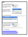
1
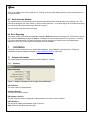
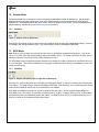
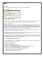
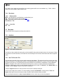
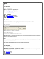
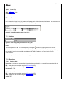
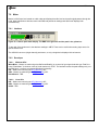
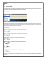
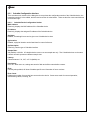
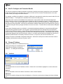
07January 2010
ASIControl
AUDIO ADAPTER MIXER AND SETUP APPLICATION
1
INTRODUCTION
ASIControl is an application that allows you to setup and control the functions of an AudioScience sound card when
running with the WAVE, WDM or Combo WAVE/WDM drivers. The basic outline and functions a user will typically
see in ASIControl are outlined in this document.
Below is a screenshot of ASIControl on a computer with one AudioScience ASI5044 adapter in it. Each adapter
appears on the left pane as a ‘topology’, showing the various inputs and outputs and controls available. The topology
is further broken up into ‘nodes’ (in the screenshot below, the Player 1 node is selected), and the nodes are then
broken up into ‘controls.’
Clicking on a particular Player, Recorder, Line_Out or Line_In node will bring up all the controls associated with it on
the right hand side. In this screenshot, the controls for Player_1 of the ASI5044 are shown in the right side of
ASIControl.
www.audioscience.com
1
07 January 2010
ASIControl
2
REVISIONS
Date
Description
21 October 2008
30 September 2008
Formatting changes.
Updated to newer format.
Section 8.2: removed incorrect info; a CobraNet device can’t receive what
it transmits.
Updated Section 8.
15 September 2009
07 January 2010
www.audioscience.com
2
07 January 2010
ASIControl
3
CONTENTS
1
INTRODUCTION ....................................................................................................................................................... 1
2
REVISIONS ............................................................................................................................................................... 2
3
CONTENTS............................................................................................................................................................... 3
4
LIST OF FIGURES.................................................................................................................................................... 5
5
INSTALLATION ........................................................................................................................................................ 6
6
USER INTERFACE................................................................................................................................................... 6
6.1
6.2
6.3
6.4
7
ADAPTER LIST WINDOW......................................................................................................................................................6
ADAPTER TOPOLOGY WINDOW ...........................................................................................................................................6
NODE CONTROLS WINDOW .................................................................................................................................................7
ERROR REPORTING ..............................................................................................................................................................7
CONTROLS .............................................................................................................................................................. 7
7.1
ADAPTER INFORMATION ......................................................................................................................................................7
7.1.1
Interface ......................................................................................................................................................................7
7.2
ADAPTER MODE ..................................................................................................................................................................8
7.2.1
Interface ......................................................................................................................................................................8
7.3
SSX2 MODE ........................................................................................................................................................................8
7.3.1
Interface ......................................................................................................................................................................8
7.4
PLAYER ...............................................................................................................................................................................9
7.4.1
Interface ......................................................................................................................................................................9
7.4.2
How To Play a File .....................................................................................................................................................9
7.4.3
Using embedded sine wave generator.........................................................................................................................9
7.4.4
Developer..................................................................................................................................................................10
7.4.4.1 Windows APIs ......................................................................................................................................................10
7.4.4.2 Linux APIs............................................................................................................................................................10
7.5
RECORDER .........................................................................................................................................................................10
7.5.1
Interface ....................................................................................................................................................................10
7.5.2
How To Record a File...............................................................................................................................................10
7.5.3
Developer..................................................................................................................................................................11
7.5.3.1 Windows APIs ......................................................................................................................................................11
7.5.3.2 Linux APIs............................................................................................................................................................11
7.6
VOLUME ............................................................................................................................................................................11
7.6.1
Interface ....................................................................................................................................................................11
7.6.2
Developer..................................................................................................................................................................11
7.6.2.1 Windows APIs ......................................................................................................................................................11
7.6.2.2 Linux APIs............................................................................................................................................................12
7.7
LEVEL ................................................................................................................................................................................12
7.7.1
Interface ....................................................................................................................................................................12
7.7.2
Developer..................................................................................................................................................................12
7.7.2.1 Windows APIs ......................................................................................................................................................12
7.7.2.2 Linux APIs............................................................................................................................................................12
7.8
METER ...............................................................................................................................................................................13
7.8.1
Interface ....................................................................................................................................................................13
7.8.2
Developer..................................................................................................................................................................13
7.8.2.1 Windows APIs ......................................................................................................................................................13
7.8.2.2 Linux APIs............................................................................................................................................................13
7.9
CHANNEL_MODE ..............................................................................................................................................................14
7.9.1
Interface ....................................................................................................................................................................14
7.10 AESEBU_RECEIVER .........................................................................................................................................................15
7.10.1 Interface ....................................................................................................................................................................15
www.audioscience.com
3
07 January 2010
ASIControl
7.11 SAVE/RESTORE CONFIGURATION ......................................................................................................................................15
7.11.1 Interface ....................................................................................................................................................................16
8
COBRANET ............................................................................................................................................................ 17
8.1
SETTING UP AUDIOSCIENCE SOFTWARE TO CONFIGURE COBRANET ................................................................................17
8.1.1
Install the Network Driver ........................................................................................................................................17
8.1.2
Select Networked Adapters in ASIControl ................................................................................................................17
8.1.3
Connect CobraNet Device to the Network ................................................................................................................18
8.1.4
Connect PC to the Network.......................................................................................................................................18
8.2
CONFIGURING COBRANET USING ASICONTROL ...............................................................................................................18
8.2.1
CobraNet Configuration Interface............................................................................................................................19
8.2.1.1 CobraNet Device Configuration Section ..............................................................................................................19
8.2.1.2 Transmitter Section...............................................................................................................................................20
8.2.1.3 Receiver Section ...................................................................................................................................................21
8.2.1.4 User Control Buttons ............................................................................................................................................21
8.3
HOW TO CONFIGURE AND TRANSMIT A BUNDLE...............................................................................................................22
8.4
CHANGE IP ADDRESS ........................................................................................................................................................22
8.4.1
Interface ....................................................................................................................................................................22
8.5
CONFIGURE COBRANET IP ADDRESS RANGE ....................................................................................................................23
8.6
CHOOSE A NETWORK INTERFACE ......................................................................................................................................23
8.7
COBRANET REFERENCES ...................................................................................................................................................23
9
ASICONTROL COMMAND LINE OPTIONS.......................................................................................................... 24
10
10.1
10.2
10.3
10.4
10.5
10.6
10.7
PROGRAMMING APIS ....................................................................................................................................... 25
HPI....................................................................................................................................................................................25
ASX ..................................................................................................................................................................................25
WAVE ................................................................................................................................................................................25
DIRECTSOUND ...................................................................................................................................................................25
ASIO .................................................................................................................................................................................26
ALSA................................................................................................................................................................................26
REFERENCES ......................................................................................................................................................................26
www.audioscience.com
4
07 January 2010
ASIControl
4
LIST OF FIGURES
FIGURE 1. BUS-BASED AND NETWORK ADAPTERS SEEN IN ASICONTROL ...........................................................................................6
FIGURE 2. ADAPTER INFORMATION SEEN IN RIGHT SIDE OF ASICONTROL. ........................................................................................7
FIGURE 3. ADAPTER MODE IN ASICONTROL. .....................................................................................................................................8
FIGURE 4. ADAPTER INFORMATION SEEN IN RIGHT SIDE OF ASICONTROL. ........................................................................................8
FIGURE 5. A PLAYER IN ASICONTROL. ..............................................................................................................................................9
FIGURE 6. A RECORDER IN ASICONTROL.........................................................................................................................................10
FIGURE 7. .A VOLUME OF A PLAYER IN ASICONTROL. .....................................................................................................................11
FIGURE 8. USING ASICONTROL TO SELECT LINE_OUT 1..................................................................................................................12
FIGURE 9. LEVEL DISPLAYED BY ASICONTROL FOR LINE_OUT 1. ...................................................................................................12
FIGURE 10. A STEREO PEAK METER DISPLAY. THE RMS IS THE GREEN BAR AND THE PEAK IS THE YELLOW BAR.............................13
FIGURE 11. ASICONTROL VIEW OF A PLAYER’S CHANNEL MODE CONTROL. ....................................................................................14
FIGURE 12. AESEBU_RECEIVER AS SEEN IN ASICONTROL.............................................................................................................15
FIGURE 13. RIGHT-CLICKING ON A COBRANET DEVICE....................................................................................................................15
FIGURE 14. THE SAVE CONFIGURATION DIALOG BOX. .....................................................................................................................16
www.audioscience.com
5
07 January 2010
ASIControl
5
INSTALLATION
ASIControl is installed with all AudioScience Windows drivers from version 3.10 Onwards. There is no separate
install. If you installed the driver with network support then ASIControl will allow you to interact with AudioScience and
other third party CobraNet devices. Otherwise only bus based (i.e. PCI and/or PCI Express) adapters will be
recognized.
6 USER INTERFACE
ASIControl consists of three main windows: the adapter list in the top portion of the window, the adapter topology view
on the left hand side and the node control list on the right hand side.
6.1
Adapter List Window
The top portion of ASIControl shows a list of all the adapters that the application has found. By default, only bus
based (i.e. PCI and/or PCI Express) adapters will be shown. If network support has been installed with the driver then
AudioScience and other 3rd party CobraNet devices will be shown.
Adapters are listed in order of adapter index. For bus-based adapters, this is determined by the adapter index jumper
on the card. For AudioScience CobraNet devices such as the ASI2416 this is calculated from the units MAC address.
3rd party CobraNet devices are listed last as they have no AudioScience index.
Figure 1 below shows an adapter list with four adapters in it. The two bus based adapters, the ASI5044 and ASI89212200, have indexes of 1 and 3 respectively that correspond to the adapter index jumper. The ASI2416 CobraNet
adapter has an index of 1094, calculated from its MAC address. The last adapter is an ASI6416. It is present in a
remote computer, but is visible over the network as a CobraNet device.
Figure 1. Bus-based and network adapters seen in ASIControl
6.2
Adapter Topology Window
The left hand side of ASIControl contains the topology view of the adapter. It is essentially a block diagram of the
device showing the available physical inputs and outputs on the right hand side. On the left hand side, bus based
adapters show player and recorder streams, while CobraNet adapters show their network connections.
Each of these inputs and outputs is referred to as a Node and each Node contains one or more Controls on it. The
topology shows each Control as a small square icon. A non-exhaustive list of nodes follows:
Line In
Line Out
AES/EBU In
AES/EBU Out
Player
Recorder
Tuner
Clock Source In
CobraNet In
CobraNet Out
Hovering the mouse over a particular node will highlight it. Clicking on a node will bring up the controls resident on
that node in the right hand control list.
www.audioscience.com
6
07 January 2010
ASIControl
There is an adapter node in the top left corner. Clicking on this will show adapter specific controls and properties on
the right hand side.
6.3
Node Controls Window
The right hand side of ASIControl shows the controls associated with the selected node on the topology view. The
controls are arranged, from top to bottom, in order of audio signal flow, i.e. the audio signal can be viewed as entering
the node at the top control and leaving at the bottom control.
The next section covers the controls in detail.
6.4 Error Reporting
The bottom, center of the ASIControl application displays “No Errors” when all is working well. If ASIControl catches
any errors, the "No Errors" changes to "Errors." Clicking there once will open up the Error Log window. Choosing
Log-->Save will save the file to a specified location; useful for sending in to AudioScience for troubleshooting.
Options to "Clear" and "Close" the Error Log window are also available.
7
CONTROLS
Following is a list of controls found on AudioScience adapters. Not all adapters have all controls. Please see
datasheets on specific adapters, available at www.audioscience.com, to learn more.
7.1
Adapter Information
This control displays information about the installed adapter or ASI2416.
7.1.1
Interface
Figure 2. Adapter information seen in right side of ASIControl.
Serial Number:
The serial number is displayed here.
Hardware Revision:
This lists the hardware revision.
DSP Software Version:
The DSP software version is displayed; usually the same as the driver version installed.
DSP Utilization:
This shows the loading of the adapter’s DSP in percent.
Note: Utilization should be kept below 90%.
www.audioscience.com
7
07 January 2010
ASIControl
7.2
Adapter Mode
The Adapter Mode control changes the number of players/recorders/lineouts that an adapter has. Not all sample
rates/formats are supported; changing the mode of the adapter allows for best functionality with certain sample
rates/formats. Not all adapters have the same modes, and not all adapters have modes. Please see datasheets on
specific adapters, available at www.audioscience.com, to learn more.
7.2.1
Interface
Figure 3. Adapter mode in ASIControl.
Selecting the appropriate mode from the list using the dropdown arrow changes the Adapter Mode setting. A reboot
is necessary after changing adapter mode. The mode setting is saved to the adapter’s EEPROM.
7.3
SSX2 Mode
Note: Driver 4.02.00 or higher is required to see this control in AudioScience adapters that support it. (For drivers
3.08 to 3.14, SSX2 mode was implemented by altering the ASIDRV.INI file. For further information on SSX2, see its
datasheet under the Technology section at www.audioscience.com.)
The SSX2 Mode control changes the players/recorders of an adapter to be able to play/record multichannel files of 2,
4, 6, or 8 channels. This control is available in the right pane of ASIControl after clicking on the adapter’s name in the
left pane of ASIControl.
7.3.1
Interface
Figure 4. Adapter information seen in right side of ASIControl.
Selecting “On” using the dropdown arrow changes the SSX2 Mode setting. A reboot is necessary after changing the
mode setting. The mode setting is saved to the adapter’s EEPROM. After rebooting, one multichannel play or record
stream will be created for each 4 play or record streams on the adapter.
SSX2 Mode and Adapter Mode can be used in conjunction with each other. Set the required Adapter Mode, set
SSX2 Mode to On, then reboot. For example, an ASI6518 set to “16-Play” in Adapter Mode and “On” in SSX2 Mode,
the ASI6518 will show 4 multichannel players after reboot. An ASI6518 set to “8-Play” in Adapter Mode and “On” in
SSX2 to on will show 2 multichannel players after reboot.
www.audioscience.com
8
07 January 2010
ASIControl
7.4
Player
The Player control supports playback of an audio file from the computer’s hard drive.
7.4.1
Interface
Figure 5. A player in ASIControl.
The first line of static text contains the selected playback file. Below the filename is the file information; playback time
and playback bytes, the timescale select options, the player control buttons and the file repeat option.
7.4.2
How To Play a File
The first step in playing a file is to select the file to play. Use the file icon button to navigate to the desired file. After
opening the file, the complete filename, including the path, will appear immediately to the left of the file open icon. At
this point the file information is also filled in so that it contains the following fields: “Channels”, “Rate”, “Format”, and
“Bit Rate”. Most of there are self-explanatory. The “Rate” refers to the sample rate of the audio recorded in the file.
The “Bit Rate” applies only to MPEG compression and is set to 0 for all other formats.
At this point the percentage time scaling without pitch shift can be set if desired. The default of 0 indicates that time
scaling is disabled. The valid range of settings is +/- 20 percent.
The “Repeat” check box indicates whether the file should be played again after playback has completed. It can be set
either before playback has begun, or while playback is underway.
The file is now ready to be played. To start playback press the play button. At this point the “Time” and “Bytes” fields
report playback time and the number of bytes of the file that have been played. 0Once playback has started, the stop
and pause buttons can be used to stop or pause the playback.
7.4.3
Using embedded sine wave generator
Manually typing in a filename of “~” and pressing play will cause a full-scale 1 kHz sine wave to be played at 48 kHz.
The format of the filename string is: "~w, c,f,a,m,s,t".
w = waveform = SINE (default=SINE)
c = channels = 1..8 (default = 2)
f = frequency = 1000 for 1kHz (default=1000)
a = amplitude = -1 for -1dBFs (default=0dBFS, i.e. full scale)
m = channel mask = 10 for left only, 01 for right only, 11 for stereo etc (default=1 for all channels)
t = sample type = (PCM8,PCM16,PCM24,PCM32,FLOAT32), (default=FLOAT32)
s = sample rate = positive integer (default=48000) [validity depends on adapter]
Defaults can be used if the complete string is not specified, i.e.
"~" -> "~wSINE,c2,f1000,a0,m11,s48000,tFLOAT32"
www.audioscience.com
9
07 January 2010
ASIControl
Any subset of the options may be specified, the remaining options will be set to the defaults. e.g. "~f500" = 500Hz
stereo sine wave at 0dBFS, 48kHz sample rate.
7.4.4
Developer
7.4.4.1 Windows APIs
Wave – waveOutOpen(), waveOutWrite(), waveOutClose() etc.
HPI – Output stream functions documented here.
ASX – ASX Player control functions documented here.
DirectSound – TBD.
7.4.4.2 Linux APIs
HPI – TBD.
7.5
Recorder
The Recorder control supports recording of an audio file.
7.5.1
Interface
Figure 6. A recorder in ASIControl.
The first line of text contains the name given to the recorded file along with the location where it is to be saved. Below
the filename is the file information, the record time and record bytes, the recorder control buttons and the file Append
option.
7.5.2
How To Record a File
The first step in recording a file is to have audio coming into the adapter. This can be from a line-in or from one of the
players in ASIControl. See appropriate sections in this datasheet to accomplish this. Next, the new file needs a name
and place to be saved, or an existing audio file can be selected to be overwritten or appended to. Use the file icon
button to navigate to the location to create the file and to give it a name, or to open a previously recorded file to
overwrite or append to it. Next, from the dropdown arrows, select the number of “Channels”, the “Sample Rate”, the
“Format”, and the “Bitrate” that the file should be recorded in.
Check the Append checkbox to save the audio to the end of an already existing file.
The file is now ready to be recorded. To start recording, press the record button. At this point the “Time’ and
“Bytes’ fields report record time and the number of bytes of the file that have been recorded.
Once recording has started, the stop and pause buttons can be used to stop or pause the playback.
www.audioscience.com
10
07 January 2010
ASIControl
7.5.3
Developer
7.5.3.1 Windows APIs
Wave – use waveInOpen(), waveInStart() etc.
HPI – use HPI_InStreamxxx() functions.
ASX – use ASX_Recorder_xxx() functions.
DirectSound – TBD.
7.5.3.2 Linux APIs
HPI – use HPI_InStreamxxx() functions.
ASX – use ASX_Recorder_xxx() functions.
ALSA – TBD
7.6
Volume
The Volume control allows the audio signal’s gain to be altered in the range of –100 to +20dB.
7.6.1
Interface
Figure 7. .A Volume of a Player in ASIControl.
Left and Right display boxes:
Displays the gain settings that the slider bars are set to.
Slider Bars:
Click on the bar with the mouse and drag to desired gain. Once the bars are selected, the left and right arrow keys
can also be used to change the settings.
Lock:
When checked, locks the left and right channels to the same gain value. When unchecked, allows the left and right
channels to have independent gains.
Autofade:
When pressed, automatically fades the volume to the opposite end of the scale.
7.6.2
Developer
7.6.2.1 Windows APIs
Wave/Mixer – MIXERCONTROL_CONTROLTYPE_VOLUME
This is a Windows standard volume control. Settings are in the range of 0 to 65535, where 0 completely mutes the
output and 65535 is the maximum volume.
HPI – HPI_Volume APIs.
ASX – ASX_Volume APIs.
DirectSound – TBD.
www.audioscience.com
11
07 January 2010
ASIControl
7.6.2.2 Linux APIs
HPI –HPI_Volume APIs.
ASX –ASX_Volume APIs.
ALSA – TBD.
7.7
Level
The levels for the adapter’s analog line_outs and line_ins can be adjusted using the level control.
In the example below, the Line_Out 1 node in the topology view of ASIControl has been selected. Its Level will show
up on the right side of ASIControl. The same is done for a Line_In to see its Level.
Figure 8. Using ASIControl to select Line_Out 1.
7.7.1
Interface
Figure 9. Level displayed by ASIControl for Line_Out 1.
Level:
The level is specified in dBu. It can be adjusted by clicking the
arrows or by typing values in the edit box.
The level value represents the maximum output of a Line_Out and the maximum input (before clipping) of a Line_In.
For example if you wish to use a +4dBu nominal level with 16dB of headroom, you would set the level to
4+16=+20dBuV.
Consult the specification section for the range of supported levels.
7.7.2
Developer
7.7.2.1 Windows APIs
Wave/Mixer – Analog levels are controlled using mixerSetControlDetails() on a control of type signed and with the
name Level/Trim.
HPI – Analog levels are controlled using the HPI_LevelSet() API.
ASX – Analog level are controlled using the ASX_Level_Set() API.
DirectSound – TBD.
7.7.2.2 Linux APIs
HPI – Analog levels are controlled using the HPI_LevelSet() API.
ASX – Analog level are controlled using the ASX_Level_Set() API.
ALSA – TBD.
www.audioscience.com
12
07 January 2010
ASIControl
7.8
Meter
Meters in ASIControl are located on audio nodes and display the audio level as the audio signal passes through the
node. Most AudioScience devices return both RMS and peak level readings and ASIControl displays both
simultaneously.
7.8.1
Interface
Figure 10. A stereo peak meter display. The RMS is the green bar and the peak is the yellow bar.
To the right of the peak meter is the absolute readings in dBFS. These can be useful when testing input tones of a
specific known level.
The ASI2416 has mono (single channel) peak meter, so only a single bar is displayed in that instance.
7.8.2
Developer
7.8.2.1 Windows APIs
Wave/Mixer – Meters are read using mixerGetControlDetails() on a control of type signed and with type “Peak” the
name “Peak Meter”. A minimum value is 0 and maximum is 32767. The interface returns the peak readings only, not
the RSM level. It confirms to expected Windows functionality.
HPI – Meters are read using the HPI_Meterxxx() API.
ASX – Meters are read using the ASX_Meter_xxx() API.
DirestSound – TBD.
7.8.2.2 Linux APIs
HPI – Meters are read using the HPI_Meterxxx() API.
ASX – Meters are read using the ASX_Meter_xxx() API.
ALSA – TBD.
www.audioscience.com
13
07 January 2010
ASIControl
7.9
Channel_Mode
The channel mode is a mechanism for handling mono to stereo conversions and directing the output to either left or
right channels, as well as outputting left to stereo and right to stereo.
7.9.1
Interface
Figure 11. ASIControl view of a player’s channel mode control.
Default playback of either mono or stereo files causes audio to be output from the player on both the left and right
audio channels. The channel mode control can allow the audio to be directed to either the left only or the right only.
Select a channel mode setting from the dropdown list.
Valid settings are:
Normal – left channel out left channel, right channel out right channel
Left
Right
Left
Right
Swap – left channel out right channel and right channel out left channel
Left
Right
Left
Right
Left_to_stereo – left channel out to both left and right channels
Left
Right
Left
Right
Right_to_stereo – right channel out to both left and right channels
Left
Right
Left
Right
Stereo_to_left – left and right channels out to left channel
Left
Right
+
Left
Right
Stereo_to_right – left and right channels out to right channel
Left
Right
+
Left
Right
The Stereo_to_left and Stereo_to_right operations perform a sum of the left and right channels and then divides the
result by 2.
www.audioscience.com
14
07 January 2010
ASIControl
7.10 AESEBU_Receiver
Check to see if valid AES/EBU signal is received and its sample rate. For adapters that support it, the digital format
can be selected; either AES/EBU (professional) or S/PDIF (consumer).
7.10.1 Interface
Figure 12. AESEBU_Receiver as seen in ASIControl.
Error Status:
When a valid digital input is received, the fields turn green (CRC is not used). If any errors, the fields in question turn
red.
Sample Rate:
The sample rate of the incoming audio is displayed.
AES/EBU Format:
For adapters that support this, the digital format can be specified; either AES/EBU (professional) or S/PDIF
(consumer).
7.11 Save/Restore Configuration
Save a device’s settings (trim, level, etc.), as set up in the left pane of ASIControl, for later retrieval using the Save
and Restore options. These options are found in ASIControl by right clicking on the device as shown in the image
below.
Figure 13. Right-clicking on a CobraNet device.
www.audioscience.com
15
07 January 2010
ASIControl
7.11.1 Interface
Figure 14. The Save Configuration dialog box.
Use the default location to save configuration settings, or use the Save in dropdown arrow to browse to a different
location. Give the file a meaningful name in the File name text box. Click the Save button; the configuration file is
saved as type xml.
To retrieve the file, simply select the Restore Configuration option and if necessary, browse to the location of the
saved xml file. Click the Open button to install the configuration settings.
www.audioscience.com
16
07 January 2010
ASIControl
8 COBRANET
ASIControl can be used to configure both AudioScience CobraNet devices and third party CobraNet devices, via its
CobraNet Configuration dialog box. This dialog box can be used to configure CobraNet devices and assign names,
locations, bundle numbers, channel assignments, etc. Third party applications such as CobraNet Discovery can also
be used to configure AudioScience CobraNet devices.
Below lists how to set up AudioScience’s software so ASIControl may be used to configure CobraNet.
NOTE: Under some Windows operating systems, ASIControl must be run as administrator in order to see all
networked CobraNet devices. In Windows 7 this is done by right clicking on the ASIControl shortcut on the desktop
and selecting “Run as administrator.”
NOTE: Some antivirus programs and/or firewalls can prevent ASIControl from showing all CobraNet devices on a
CobraNet network. If all CobraNet devices are not showing in the top pane of ASIControl, please check settings
and/or turn off any antivirus programs or firewalls that may be running on the PC.
8.1
Setting Up AudioScience Software to Configure CobraNet
To configure an AudioScience CobraNet devices using ASIControl, the following must be in place: the AudioScience
network driver must be installed, the networked adapters option must be selected in ASIControl, the AudioScience
CobraNet device must be connected to the CobraNet network via an Ethernet cable, and the PC that is running
ASIControl must also be connected to the same CobraNet network.
8.1.1
Install the Network Driver
When an AudioScience driver install EXE is run, three choices are made available as shown in the image below.
Select “Install Standard + Network Audio Driver” when installing AudioScience CobraNet products, then run the driver
install EXE as usual.
8.1.2
Select Networked Adapters in ASIControl
In ASIControl, go to the menu item Options, then select Configure adapter interface, as shown to the left.
Since ASIControl is used for both AudioScience’s non-CobraNet
adapters and CobraNet adapters, the correct interface must be
selected when using ASIControl for CobraNet configuration. Click on
menu item Options, then Configure adapter interface.
The Interface Selection dialog box opens; the default selection is “Local PCI(e) adapters. Select ‘Local PCI(e) +
Networked adapters.’ then click OK.
ASIControl will restart, looking for all CobraNet devices on the network, assigning IP
addresses where needed, and showing CobraNet devices on the network in its top
pane.
www.audioscience.com
17
07 January 2010
ASIControl
8.1.3
Connect CobraNet Device to the Network
Plug one end of an Ethernet cable into the back of the AudioScience CobraNet device. Plug the other end into the
CobraNet or test network.
8.1.4
Connect PC to the Network
CobraNet control is via SNMP. In order for ASIControl to establish an SNMP connection to an AudioScience (or
other) CobraNet device(s) for configuring, a valid network path must be established between the PC running
ASIControl and the AudioScience (or other) CobraNet device(s). This is done by plugging one end of an Ethernet
cable into the back of the PC’s network interface card (NIC) and plugging the other end into the CobraNet or test
network.
If the PC running ASIControl must be connected to an office network and if the CobraNet network data is required to
be separate from the office network, another NIC must be added to the PC; one for the office and one for CobraNet.
If the PC is on an office network and the CobraNet network data is not required to be separate from the office
network, the PC can temporarily be removed from the office network and plugged into the CobraNet or test network.
After the CobraNet configurations are made, the PC can be taken off the CobraNet network and placed back on the
office network. Note: If any CobraNet configurations need to be changed in the future, the PC must be placed back
on the CobraNet network in order to establish the SNMP connection.
If the PC does not need to be on an office network, plug it’s NIC into the CobraNet or test network and either leave it
there or remove it after configuring CobraNet. If it’s removed, the PC must be connected to the CobraNet or test
network again if CobraNet configurations need to be changed in the future.
Note: If plugging an AudioScience CobraNet device into an already existing CobraNet network, the PC must have the
same IP address range as the CobraNet network in order for it to assign the AudioScience CobraNet device an IP
address in the same range. Alternatively, if another CobraNet set-up application was used such as CobraNet
Discovery, the same application may be used to assign an IP address and configure AudioScience CobraNet devices.
8.2
Configuring CobraNet Using ASIControl
The CobraNet Configuration dialog box is accessed via ASIControl,
which is installed when the driver EXE is run. Double click on the ASIControl icon
on the desktop, then in the top section right click on the CobraNet device and
select Configure CobraNet… shown below left, and the CobraNet Configuration dialog box opens, shown below right.
www.audioscience.com
18
07 January 2010
ASIControl
8.2.1
CobraNet Configuration Interface
There are three main sections of the dialog box: the top shows the configuration section of the CobraNet device, the
transmitter section is in the middle, and the receiver section is at the bottom. There are also four user control buttons
on the bottom right.
8.2.1.1 CobraNet Device Configuration Section
MAC Address:
Read only; displays the MAC address of the CobraNet device.
IP Address:
Read only, displays the assigned IP address of the CobraNet device.
SysName:
Editable; a meaningful name can be given to a CobraNet device here.
SysLocation:
Editable; a physical location can be listed here for ease of reference.
SysDescription
Read only; lists the type of CobraNet interface.
Sample Rate:
48k (default) or 96 kHz. A CobraNet device must run at one sample rate only. Two CobraNet devices on the same
network can each operate at a different sample rate.
Latency:
Choose between 1.33, 2.67, or 5.33 (default) ms.
Persistence:
On or off. When set to on, settings are saved to flash and will be restored after a restart.
Error:
Currently always blank, will show CobraNet specific error information in future versions.
Error Count:
Displays the number of errors that have occurred on the device. Some errors result from normal operation;
disconnecting cables, rerouting, etc.
www.audioscience.com
19
07 January 2010
ASIControl
8.2.1.2 Transmitter Section
Transmitter:
Sends an audio bundle, made up of up to 8 audio channels, to a CobraNet receiver on the network.
Bundle:
The basic CobraNet audio routing component, can have 0 to 8 audio channels. Assign specific bundle numbers here.
Bundle numbers can be 0 and 1 – 65535
- 0 for turning transmitter off or for silence
- 1-255 for multicast
- 256-65279 for unicast
- 65280-65535 for private
1-8 Audio Channels:
The number of mapped channels from mixer to transmitter. Channels 0 (inactive) and 1-32 can be assigned. A 0
mapping of end channels ‘shortens’ the bundle; a mapping of 0 in the middle of mapping denotes silence.
Multicast Mode:
Double click to change setting in the dropdown list; use the following table to determine what setting to select:
Settings
Multicast Bundle # < 256
Always
Unicast N
Number of Receivers <= N
Multicast
Multicast
Unicast
Multicast Over N
Unicast
Number of Receivers > N
Multicast
Multicast
Unicast if Receiver = 1-N
Fail if Receiver > N
Multicast
Format:
Double click to change the audio sample format to 16, 20, or 24 bits.
Dropouts:
The number of times the channel transmission has been interrupted. Interruptions can be caused by loss of transmit
permission from conductor (i.e. conflict with another transmitter set to the same bundle number) or by changes to
txBundle.
Receivers:
The number of receivers requesting this bundle.
www.audioscience.com
20
07 January 2010
ASIControl
8.2.1.3 Receiver Section
Receiver:
Can receive from a CobraNet transmitter on the network one bundle made up of up to 8 audio channels.
Bundle:
The basic CobraNet audio routing component; assign a specific Bundle number here. A Receiver can carry 0
(channel will not be mapped to mixer) to 8 audio channels.
1-8 Audio Channels:
The number of audio channels in the bundle to be routed to the particular Receiver; channels 0 (inactive) and 33-64
can be assigned.
Status:
Displays ‘Receiving’ when a bundle is successfully routed to it.
Dropouts:
Displays number of times bundle reception has been interrupted. Interruptions can be caused by transmitter failure or
by reconfiguring the receiver.
8.2.1.4
User Control Buttons
Refresh:
Updates fields and statuses. If clicked before Apply, clears any changes made.
Apply:
Accepts changes and leaves dialog box open.
OK:
Accepts changes and closes dialog box.
Cancel:
Does not accept any changes made and closes dialog box.
www.audioscience.com
21
07 January 2010
ASIControl
8.3
How To Configure and Transmit a Bundle
The minimum configuring needed to test basic functionality of sending and receiving a bundle is to set a transmitter
bundle and channels on one CobraNet device, and then set the receiver of another CobraNet device to the same
bundle number, plus assign its channel numbers.
For example, an ASI6416 is installed in a computer, ASIControl is opened and is used to play a stereo audio file in the
ASI6416’s Player 1. The Repeat box is checked to have continuous audio playing.
ASIControl is then used to set the ASI6416’s first transmitter to have bundle number and channel assignments.
Double clicking in receiver 1’s bundle field makes it editable and 255 (for example) is typed in. Double clicking in the
receiver 1, channel 1 box makes it editable and 1 is typed in (numbers 0 and 1-32 can be used). Hitting the Tab key
auto fills the rest of the channels. Since only two channels are needed, double clicking in the channel 3 box, typing in
0, and then hitting the Tab key changes channels 3-8 to have 0s in them. The OK button is clicked and the dialog box
closes.
On the same CobraNet network is an ASI2416. Its CobraNet Configuration dialog box is opened using ASIControl.
Using the same procedures as above, 255 is typed in (since 255 was used in the example above) as the bundle
number for the ASI2416’s receiver 1, and its first two channels are assigned numbers 33 and 34 (numbers 0 and 3364 can be used). This time the Apply button is clicked so the dialog box remains open. Immediately in the CobraNet
Configuration dialog box the first two channels in receiver 1 turn green and the Status field changes to ‘Receiving’ to
indicate a bundle has been successfully routed to the receiver. If any errors, the receivers would turn red.
Clicking OK closes the CobraNet Configuration dialog box. ASIControl is still open and meter movement is seen in
CobraNet_Ch 33 and 34, as well as Line_Outs 1 and 2.
8.4
Change IP Address
Change the IP address of a CobraNet device here.
After right clicking on a CobraNet device in
ASIControl and selecting “Change IP
Address…”, the dialog box below opens.
8.4.1
Interface
Current IP:
The CobraNet device’s current IP address is shown. Double click in the fields to highlight the current number and
overwrite it.
Static IP:
It is recommended to click on the Static IP checkbox to have a fixed IP address.
OK/Cancel:
Click OK to accept the changes and close the dialog box, or Cancel to not accept any changes and close the dialog
box.
www.audioscience.com
22
07 January 2010
ASIControl
8.5
Configure CobraNet IP Address Range
Assign a starting and ending IP address range, and enable auto-assign here.
Click on ASIControl’s menu item Options,
then select Configure CobraNet IP address
range. This opens the CobraNet Auto IP
Assignment dialog box.
Type in the starting and stopping CobraNet
IP address to be used. When Enable
Auto-assign is checked, ASIControl
assigns IP addresses to all discovered
devices according to the IP address range.
Click OK.
8.6
Choose a Network Interface
If a PC has more than one network interface card (NIC) in it, the following dialog box will pop up when first opening
ASIControl:
Select the correct NIC that the CobraNet devices will be suing, then click OK.
The network interface can be changed at
any time. To change the NIC used, click
on ASIControl’s menu item Options, then
Select network adapter. This opens the
ASIControl – choose network interface
dialog box.
NOTE: If Select network adapter is not showing under Options, close and then reopen ASIControl.
8.7
CobraNet References
http://cirrus.com/en/pubs/appNote/CobraNet_AudioRoutingPrimer.pdf
http://cirrus.com/en/pubs/manual/CobraNet_Programmer_Manual_PM25.pdf
http://www.cirrus.com/en/support/cobranet/design/switched_networks.html
www.audioscience.com
23
07 January 2010
ASIControl
9 ASICONTROL COMMAND LINE OPTIONS
ASIControl has the ability to run configuration commands from the command line. The specified action is run and
ASIControl will exit without ever bringing up the ASIControl GUI. The configuration information is stored in XML
format.
Note – as of driver version 3.10, the save/restore function does not process CobraNet controls.
Basic command line calling format is:
asictrl Command File Adapter Flag
and is implemented as follows:
Command
[SaveCfg|RestoreCfg] this field tells ASIControl which command to execute.
Default
None. This is a required field.
File
For convention sake, the file extension should be .xml.
Default
None. This is a required field.
Adapter
[<adapter index>|<adapter ip_address>|ALL|NETALL] this field tells ASIControl which adapter configurations
to save or restore.
Default
ALL. see below
ALL
All local PCI/PCIe configurations are saved to the specified file.
NETALL
All local PCI/PCIe and networked adapters’ configurations are saved to the specified file.
adapter index
Only the adapter with the specified index is saved. The first PCI adapter in a system is referenced
using adapter index 1.
ip address
Only the adapter with the specified IP address is saved.
Flag
[create|overwrite|append] this setting controls file operations for SaveCfg only.
Default
create see below.
create
create the file and add the specified adapter configurations; fails if the file exists
append
creates or opens the file and adds section(s) for specified adapters; fails if a section exists for a
specified adapter
overwrite
creates or opens the file and adds or overwrites section(s) for specified adapters
Examples:
To save settings for the first adapter in the system go
asictrl SaveCfg ASI6114_1.xml 1
To restore go
asictrl RestoreCfg ASI6114_1.xml
www.audioscience.com
24
07 January 2010
ASIControl
10 PROGRAMMING APIS
AudioScience provides a number of APIs for interfacing to its audio adapters. This section briefly describes the
interfaces and where to locate further documentation on them.
10.1 HPI
The HPI interface is an AudioScience specific interface that is support on all AudioScience products, including the
ASI2416. It is the low level interface on which all AudioScience drivers across all operating system are built (including
Linux).
Under Windows, HPI calls are surfaced to a client application via a DLL. All Windows drivers support the HPI calling
interface.
An SDK and online documentation is available on the AudioScience website:
http://www.audioscience.com/internet/download/sdk/sdk.htm
10.2 ASX
The ASX interface is supported on all operating systems, including Linux. It is an AudioScience specific interface that
supports file level record and playback. The client application does not have to provide and buffer management
routines, or create threads to feed audio to /from the audio adapter.
ASIControl is built on top of the ASX interface. It provides interfaces to all features of AudioScience adapters.
An SDK and online documentation is available on the AudioScience website:
http://www.audioscience.com/internet/download/sdk/sdk.htm
10.3 Wave
The Wave interface is only implemented under Microsoft Windows. It uses standard Microsoft compatible
waveOutXXX(), waveInXXX() and mixerXXXX() calls to play, record and mix audio. Where possible AudioScience’s
implementation is 100% compatible with other multimedia cards running under Windows.
See the references section below for a link to spcwavx.pdf that details multimedia extensions that AudioScience has
implemented to provide access to advanced audio features.
AudioScience has implemented some extensions to the standard wave API to provide access to advanced audio
features. Documentation on these APIs may be found here:
SPCWAVX.PDF - WavX - AudioScience Windows Multimedia Extensions
10.4 DirectSound
The WDM driver provides a native DirectSound interface to AudioScience sound cards. Use the standard
DirectSound APIs provided by Microsoft.
www.audioscience.com
25
07 January 2010
ASIControl
10.5 ASIO
All AudioScience Windows drivers support the ASIO programming interface. The ASIO driver is installed by default,
but is only activated by an ASIO client application.
10.6 ALSA
Under Linux, the ALSA sound programming API is supported. From version 1.0.7, snd-asihpi is part of the standard
ALSA driver source. PCM and Mixer APIs are supported.
For more details, see the Linux download page on the AudioScience website:
http://www.audioscience.com/internet/download/linux_drivers.htm
10.7 References
HPI User Manual - Hardware Programming Interface (HPI) Reference Manual
SPCWAVX.PDF - WavX - AudioScience Windows Multimedia Extensions
These documents are available from www.audioscience.com in the Documentation section.
<end>
www.audioscience.com
26
07 January 2010