1
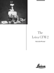
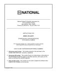
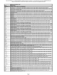
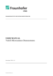
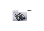
National Optical & Scientific Instruments Inc.
11113 Landmark 35 Drive
San Antonio, Texas 78233
Phone (210) 590-9010 Fax (210) 590-1104
INSTRUCTIONS FOR
MODEL DC3-163
COMPOUND BIOLOGICAL MICROSCOPE
WITH DIGITAL CAMERA
(For microscope operation only. Camera operation covered in separate
Motic Image 2000 manual included with your microscope)
HOW TO USE YOUR MICROSCOPE SERIAL NUMBERS
1. Microscope serial number: This number (etched on back arm of microscope) is the
number under which your warranty is registered.
2. Microscope DM number: This number (found on a white sticker on the bottom of the
microscope) is used for logging on the Motic web site, which gives you the ability to
download free software upgrades.
3. Motic CD DM number: This number is to be used to register the software when
loaded on the computer for the first time.
Copyright © 1/2/01
National Optical & Scientific Instrument Inc.
About the Digital Microscope
The manual for your new digital microscope is in two parts. This first part describes the basic nomenclature and
functions of the microscope, which can be used as a fully functional microscope, independent of the camera. The
second part is the Motic Images 2000 User’s Manual, which provides detailed documentation for installation and
operation of the Motic Images 2000 software. In order to achieve optimum results, it is important that you carefully
read both this and the documentation manuals before operating your microscope or camera.
UNPACKING
1. Your microscope is packed with the following components, all of which have been checked at the factory.
Carefully remove all components and check against this list. Retain styrofoam container in case microscope must
be transported or returned to factory for any reason.
A.
B.
C.
D.
E.
F.
G.
H.
I.
J.
K.
L.
M.
N.
O.
P.
Q.
Microscope body
Two WF10x eyepieces
Two rubber eyecups
Four objective lenses: DIN achromatic 4x, 10x, 40xR, 100xR oil immersion
1.25 N.A. Abbe condenser with iris diaphragm
Three filters: blue, green, yellow
Specimen holder for mechanical stage
12VDC switching power supply, operates on 100v-240v, 50H/60H
Power cord
CD Motic Images 2000 software
Two instruction manuals: this one and separate software documentation
Calibration slide
USB cable (for connecting to computer)
S cable (for connecting to high resolution video monitor)
RCA cable (for connecting to standard resolution video or projector)
Dustcover
Warranty card
2. If it becomes necessary to ship the microscope for any reason, repack it in the styrofoam container, and then pack
the styrofoam in another corrugated shipping container for optimum protection. Use of the styrofoam alone will
not provide adequate protection in transit, and will void your warranty.
A. NOTICE: To protect focus mechanism during shipment, two black plastic wedges (b) and one black plastic
block (c) are inserted at strategic points as indicated. These plastic parts MUST be removed prior to
operating microscope. Failure to do so will result in damage to focusing mechanism and will void your
warranty.
(a)
1. Remove two black velcro straps (a).
2. Remove wedge (b) by pulling apart the
two parts of wedge in opposite directions.
3. Lower stage by rotating coarse focus
knob in counter-clockwise direction.
in counter-clockwise direction
4. Remove block (c) from stand.
5. These components should be retained
with styrofoam container.
(c)
(b)
B. Carefully remove from the stand all tape and packing material used to protect microscope components during
shipment. Remove black objective plugs from nosepiece.
3
C. Unwrap components, making certain that lens surfaces do not come in contact with dust, dirt, fingerprints.
Damage to optical surfaces can result from such contaminants, and reduce image quality.
4
ASSEMBLY
Eyepiece
(4)
Objective lens
(3)
Specimen
holder
(2)
Abbe Condenser
(1)
Filter
(5)
1. Condenser: Rotate focusing knob to move stage platform to its highest position. Loosen the knurled locking
screw and insert Abbe condenser into the mounting ring. Tighten locking screw.
2. Specimen holder: Rotate coarse focusing knob to move stage platform to its lowest position. Remove two
knurled screws from mechanical stage platform. Place specimen holder on stage and using the two knurled
locking screws, attach holder to mechanical stage.
3. Objectives: With stage platform located at its lowest position. Screw all the objectives into the nosepiece,
making certain to mount them in consecutive order 4x, 10x, 40x, 100x.
4. Eyepieces: Remove the dust caps from eyepiece tubes. Avoid touching any lens surface. Insert eyepieces into
the eyepiece tubes.
5. Filters: Swing out filter holder and insert 32mm diameter blue filter.
OPERATION
1. Illumination.
A. Before operating microscope, adjust intensity control located on side of base to the minimum position. This
should be done prior to each time light is turned on or off. This will extend bulb life.
B. Insert power plug into 12VDC switching power converter, then insert plug on other end of converter into power
jack on back of microscope base. Note that the 12VDC converter will operate on either 120v or 240v current,
50 hertz or 60 hertz, eliminating the need for any other transformer.
C. Rotate intensity dial on illuminator base until image is illuminated.
D. Adjust intensity of light to match requirements of objective and specimen slide.
E. In case of equipment malfunction, see “Trouble Shooting” procedures.
5
2. Interpupillary adjustment of viewing head
A. Look through microscope and adjust distance between the two eyepiece tubes by grasping the sliding mounts
to left and right of eyepieces and sliding together or apart.
B. When a full field of view is observed through both tubes, and images blend into one, interpupillary distance is
corrected for your eyes. Check the interpupillary scale and note index reading for future reference, in case
other users will be changing this adjustment from time to time.
C. Adjust the diopter scales, located on each eyepiece tube, to the same numerical value as indicated on the
interpupillary scale. This must be done in order to maintain parfocality of objective lenses. If interpupillary
distance is changed, adjust eyepiece diopters accordingly.
3. Focusing the microscope.
A. Position the 4x objective lens into the optical path, making sure that lens is properly indexed in its click-stop
position.
B. Place standard specimen slide (cover slip up) on top of stage surface.
a) Swing moveable finger on slide holder outward. Place specimen slide against fixed side of slide holder.
Slowly release moveable finger until it makes contact with specimen slide.
C. Rotate coarse focusing controls until specimen comes into focus.
D. Adjust fine focus controls until specimen is in sharp focus.
E. Adjust diopter for difference in eyesight.
a) Using right eye, peer into the right eyepiece tube. Adjust sharpness of image by utilizing fine focus
controls.
b) Using left eye, peer into the left eyepiece tube. Adjust sharpness of image by turning diopter adjustment
located on left eyepiece tube.
F. Adjusting the aperture (opening) of iris diaphragm.
Iris diaphragm should not be used to control the brightness of illumination. Iris diaphragms are designed to
help achieve high resolution of specimen and provide contrast in the image. Smaller apertures will deliver
higher contrast to image. However, closing aperture too much will reduce resolution. Experimentation is the
best method of determining the correct opening of diaphragm. Some suggested openings for iris diaphragm
are:
OBJECTIVE
DIAPHRAGM OPENING
4x
10x
40x
100x
From fully closed to 1/8 open
1/8 to 1/4 open
1/4 to 1/2 open
1/2 to 3/4 open
G. Changing magnification.
a) Rotate revolving nosepiece to position 10x objective into optical path.
b) This microscope has been parfocalized, which allows changes from one objective to another while
requiring only a slight adjustment of the fine focus controls.
c) When changing to the 40x and 100x objective lens, care must be exercised in order to prevent damaging
the front lens element and specimen slide.
6
d) In order to obtain maximum resolution of the 100x oil immersion lens, it is necessary to apply immersion
oil between the coverglass of slide and front lens of the objective.
(1) Use of a very small amount of immersion oil is required.
(2) All air bubbles must be removed from between lens and slide by rotating nosepiece back and forth.
H. When finished viewing, all parts that come in contact with oil must be cleaned. Failure to do so could
permanently damage the 100x oil immersion objective lens. Use of xylene to clean immersion oil off lens
surfaces is recommended.
I.
Coarse focus tension adjustment.
a) Tension adjustment knob is located between stand and coarse focus knob of microscope, on the right
side.
b) To tighten tension of coarse focus knobs, turn control in a counter-clockwise direction. It is advisable to
leave controls as loose as possible, tightening only enough to keep stage from drifting down and out of
focus. To loosen tension, turn control in clockwise direction.
MAINTENANCE
WARNING: FOR YOUR SAFETY, TURN SWITCH OFF AND REMOVE PLUG FROM POWER SOURCE OUTLET
BEFORE MAINTAINING YOUR MICROSCOPE. TO AVOID SHOCK OR FIRE HAZARD, IF POWER CORD IS
WORN, CUT OR DAMAGED IN ANY WAY, HAVE IT REPLACED AT ONCE.
1. OPTICAL MAINTENANCE
A. Do not attempt to disassemble any lens component. Consult an expert technical service company when
repairs not covered by these instructions are required.
B. Prior to cleaning any lens surface, brush dust or dirt off lens surfaces using a camel hair brush. Or use air to
blow dust and lint off surfaces. Use of compressed air in a can, available at any computer supply store, is a
good source of clean air.
C. Cleaning eyepiece lenses.
Do not remove eyepiece from eyepiece tube. Clean only the outer surface. Breath on lens to dampen
surface, then wipe with lens paper. Do not wipe lens surface while dry as lenses are scratched very easily.
Wipe a circular motion from center to outer edges.
D. Cleaning objective lenses.
Do not remove objective lenses from microscope. Clean front lens element only. Using a cotton swab
saturated with distilled water, clean front lens surface. Inspect the lens using a magnifying glass to insure
that the element is clean. If immersion oil or specimen material of any kind is evident, use a cotton swab
dipped in a small amount of xylene to clean all foreign material from objective lens surface. Such material
will reduce, or totally block, image quality.
E. Cleaning condenser lens.
Clean only the top lens surface, visible when looking through hole in top of stage. Use same procedure as
used for eyepiece or objective lenses.
F. Illuminator condenser lens.
Use same procedure as used for eyepiece or objective lenses.
7
2. ELECTRICAL MAINTENANCE
WARNING: FOR YOUR SAFETY, TURN SWITCH OFF AND REMOVE PLUG FROM POWER SOURCE
OUTLET BEFORE MAINTAINING YOUR MICROSCOPE.
A. Replacement of lamp.
a) Carefully lay instrument on its side, taking care to avoid damage to the specimen slide holder located on
top of mechanical stage.
b) Loosen large chrome locking screw located on hinged door of illuminator base.
c) Swing door open to expose the halogen lamp.
d) Using a tissue or cloth to gently grasp the halogen bulb, pull straight out of lamp socket.
e) Your microscope requires a 12 volt, 20 watt halogen bulb, available from the dealer from which you
purchased your microscope. This is a common microscope bulb, Osram #64425.
f)
Make certain that new bulb is clean, as fingerprints on bulb can affect light transmission. Grasping bulb
gently with a tissue or cloth, insert pins straight into lamp socket.
g) Carefully clean lamp to assure that it is clean and free of all fingerprints.
h) Close hinged door and tighten locking screw.
TROUBLESHOOTING
PROBLEM
Light fails to operate.
Lamp flickers
Image does not remain in
focus
Poor resolution
(image not sharp)
REASON FOR PROBLEM
Outlet inoperative.
AC power cord not connected.
Lamp burned out.
Lamp loose in socket.
Cover slip on specimen slide
too thick.
Slide upside down.
Stage drops down from its own
weight.
Objective lenses dirty.
Eyepiece lens dirty.
Too much light.
SOLUTION
Have qualified service technician repair
outlet.
Plug into outlet.
Replace lamp.
Push lamp pins into lamp socket.
Use 0.17mm thick cover slip.
Place slide on stage with cover slip
facing up.
Adjust tension of coarse focus knob.
Clean objective lenses.
Clean eyepiece lenses.
Adjust intensity of light and check iris
diaphragm aperture.
Spots in field of view.
Eyepiece lens dirty.
Clean eyepiece lenses. ***
Specimen slide dirty.
Clean slide.
Condenser lens dirty.
Clean lens of condenser.
***Spots in field of view can also result from dirt on inside of eyepiece. It is recommended that you have
service technician clean inside of lens.
8
OPTIONAL ACCESSORIES AND PARTS:
#610-160
#610-160R
#704-160
#710-160
#740-160
#799-160
#704-160ASC
#710-160ASC
#740-160ASC
#799-160ASC
#704-160SP
#710-160SP
#740-160SP
#799-160SP
#704-160P
#710-160P
#740-160P
#799-160P
#800-160
#965-160
WF10X Eyepiece
WF10X eyepiece w/reticle, 10mm/100div.
DIN 4X objective lens, 0.10 N.A.
DIN 10X objective lens, 0.25 N.A.
DIN 40X objective lens, 0.65 N.A.
DIN 100X objective lens, 1.25 N.A.
DIN 4X Super High Contrast objective lens, 0.10 N.A.
DIN 10X Super High Contrast objective lens, 0.25 N.A.
DIN 40X Super High Contrast objective lens, 0.65 N.A.
DIN 100X Super High Contrast objective lens, 1.25 N.A.
DIN 4X Semi-plan objective lens, 0.10 N.A.
DIN 10X Semi-plan objective lens, 0.25 N.A.
DIN 40X Semi-plan objective lens, 0.65 N.A.
DIN 100XR Semi-plan objective lens, 1.25 N.A.
DIN 4X Plan objective lens, 0.10 N.A.
DIN 10X Plan objective lens, 025 N.A.
DIN 40X Plan objective lens, 0.65 N.A.
DIN 100X Plan objective lens, 1.25 N.A.
Replacement bulb, 12v 20 watt halogen bi-pin
Eyepiece reticle, 10mm/100 div.
WARRANTY
Microscope, 5-year limited warranty: Manufacturer warrants this instrument to be free from defects in material and
workmanship under normal use and service for 5 years from date of purchase. It does not cover damage resulting
from abuse or misuse, repairs or alterations performed by other than authorized repair technicians or damage
occurring in transit. Warranty does not cover bulbs or fuses.
Camera, 1-year limited warranty: Manufacturer warrants camera to be free from defects in material and
workmanship under normal use and service for 1 year from date of purchase. It does not cover damage resulting
from abuse or misuse, repairs or alterations performed by other than the manufacturer, or damage occurring in transit.
Software, 90-day limited warranty: Manufacturer warrants software to be free from defects in material and
workmanship under normal use and service for 90 days from date of purchase.
For warranty service, instrument should be well packed to avoid damage in transit, including a description of the
difficulty, and shipped postage prepaid to National at the address on front. National will repair or replace at no charge
and return postage prepaid. If failure was caused by misuse, alterations, accident , or abnormal conditions of
operation, an estimate for repairs will be submitted for your approval prior to work being performed.
If you have questions concerning this product or warranty, contact dealer from which it was purchased. Or contact
National, asking for warranty assistance.
(3/16/01)
9