1
MEATEST
M -150S Current Calibrator
CONTENT
1.
2.
3.
4.
5.
6.
Device Application ......................................................................................................................... 2
Content of Supply Set.................................................................................................................... 2
Technical Data............................................................................................................................... 3
Function Principle .......................................................................................................................... 5
Calibrator start ............................................................................................................................... 5
Service Instructions ....................................................................................................................... 6
6.1 Description of Control and Indication Units ............................................................................... 6
6.1.1 Front Panel ....................................................................................................................... 8
6.1.2 Rear Panel...................................................................................................................... 12
6.2 Starting the Device.................................................................................................................. 14
6.3 Control of the Calibrator .......................................................................................................... 14
6.3.1 Selection of Output Current Value.................................................................................. 14
6.3.3 Deviation Setting ............................................................................................................ 15
6.3.4 Calling Calibrator Specification....................................................................................... 15
6.3.5 Connection of Output Terminal ...................................................................................... 15
6.3.6 Tests............................................................................................................................... 16
6.4 Error Reporting........................................................................................................................ 16
6.5 System Control via GPIB bus.................................................................................................. 17
7.
Maintenance Instructions............................................................................................................. 18
8.
Calibration.................................................................................................................................... 19
8.1 Calibration Principle ............................................................................................................... 19
8.2 Calibration Procedure.............................................................................................................. 19
8.2.1
Calibrating Code............................................................................................................ 20
8.2.2
Calibration of Current Range......................................................................................... 21
8.3 Check of Parameters .............................................................................................................. 26
8.3.1 Check of Current Ranges............................................................................................... 27
8.3.2
Check of non-linear distortion....................................................................................... 28
8.3.3 Frequency Check ............................................................................................................... 28
User's manual
1
MEATEST
1.
M -150S Current Calibrator
Device Application
The current calibrator M-150S can supply very stable calibrated DC and AC currents. The
output current value can be set within one range with the resolution correct to four decimal places. The
frequency can be set in range
from 40 Hz to 120 Hz with the possibility of setting six discrete
frequencies. The very good time stability of amplitude is determined by the voltage reference of the
eighteen-bit DAC729 converter. The microprocessor used for the inner control enables easy service in
the manual control mode and secures the full compatibility with the GPIB bus. The low non-linear
distortion factor enables the device’s application for calibration of measuring instruments indicating
both the average and effective values, respectively the peak output values. The calibrator is intended
especially for calibration of analogue and digital ammeters.
2.
Content of Supply Set
Calibrator M-150S
1 pc
Supply cable
1 pc
Fuse
1 pc
Service instructions
1 pc
User's manual
2
MEATEST
3.
M -150S Current Calibrator
Technical Data
DC Current Output
Total current range:
from 9 A to 100 A
Accuracy:
% of the value + % of the range
frequency range
DC
100 A
0.1 + 0.1
range of values
from 9 A to 100 A
- valid for the reference temperature of 23 ° C ± 2 ° C during the period of 12 months.
- the range of values is valid with the ERR function put out of operation.
- voltage on load
:1V
- current resolution:
4 digit
AC Current Output
Total current range:
from 9 A to 100 A
Accuracy:
% of the value + % of the range
frequency range
from 40 Hz to 120 Hz
100 A
0.1 + 0.1
range of values
from 9 A to 100 A
- valid for the reference temperature of 23 ° C ± 2 ° C during the period of 12 months
- the range of values is valid with the ERR function put out of operation.
- non-linear distortion
0.3 % for resistance load
- frequency
40 Hz, 50 Hz, 60, 08, 100, 120 Hz
- load voltage
1 Vef
- current resolution
4 digit
- frequency accuracy
0.01 %
User's manual
3
MEATEST
M -150S Current Calibrator
DC Current Output - External Input
Total current range:
from 9 A to 100 A
Input voltage:
from ± 0.9 to ± 10 V
Accuracy:
% of value + % of range
frequency range
DC
100 A
0.1 + 0.2
range of values
from 9 A to 100 A
- accuracy does not include uncertainty of the external reference
- valid for the reference temperature of 23 ° C ± 2 ° C during the period of 12 months
- the range of values is valid with the ERR function put out of operation.
- voltage on the load:
1V
- maximum input voltage: ± 10 V
AC Current Output - External Input
Total current range:
Input voltage:
from 9 A to 100 A
from 0.9 to 10 Vef
Accuracy:
% of value + % of range
frequency range
from 40 Hz to 120 Hz
100 A
0.1 + 0.3
range of values
from 9 A to 100 A
- accuracy does not include uncertainty of the external reference
- the maximum input voltage:
10 Vef
- frequency range:
from 40 Hz to 120 Hz
- voltage on the load:
1 Vef
- current resolution:
4 digit
General Data
Warm up time:
20 minutes
Operating temperature range:
23 ± 10 ° C
Relative humidity:
45 to 75 %
Storage temperature range:
0 to 40 ° C at the relative humidity of 80 %
Reference temperature:
23 ° C
Air pressure:
86000 to 106000 Pa
Outer electric field:
inconsiderably low
Outer magnetic field:
inconsiderably low
Dimensions:
460 x 520 x 320 mm
Voltage supply:
220 V / 50 Hz
Power input:
max. 800 VA
User's manual
4
MEATEST
Control:
M -150S Current Calibrator
- manual with micro-switches on the front panel
- remote control, through GPIB bus
Indication:
2 four-digit displays indicating
- output current
- frequency
- specification
- deviation reading
- error reporting
4.
Function Principle
The calibrator is based on the stable DC voltage reference derived from the eighteen-bit
converter DAC 729. The whole range of DC and AC currents is derived from the reference voltage
value. The digital harmonic voltage generator works on the basis of the sine wave synthesis through
the step approximation by means of a 12-bit D/A converter. The D/A converter is a multiplying
converter with controlled current supplies. The feedback loop control voltage is used as the reference
voltage. Data defining the sine signal wave are saved in the fixed PROM memory. The output AC
voltage is very stable in respect of temperature and time. To reduce higher harmonic frequencies, the
sine wave is also filtered in the low-pass filter with the breaking frequency, which does not allow
exceeding of output signal distortion by more than 0.1 %. The amplitude regulation circuit is controlled
by the deviation amplifier integrator. The deviation amplifier compare the calibrator’s output voltage
with the variable direct current reference and generates the control voltage for setting up the amplitude.
Generating DC or AC voltage (according to the mode) is led to the voltage/current converter, to the
output current amplifier and to the output terminal. The amplitude feedback includes the
voltage/current converter and the output amplifier.
The microprocessor’s circuits secure a correct function of the display and the keyboard and mediate
the co-operation of single analogue blocks, the connection to the GPIB bus and carry out required
mathematical calculations.
5.
Calibrator start
If the device was stored at the temperature lower than 5 ° C, it’s necessary to acclimatise it for
2 hours under operating and working conditions. The device can be switched on by pressing the power
button (POWER) located in the front panel. The device is constructed for the power supply from the
mains 230V / 50 Hz. The exposed metal parts are connected to the protective conductor (except the
output terminal).
User's manual
5
MEATEST
6.
Service Instructions
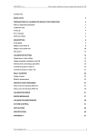
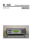
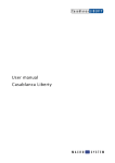
6.1
Description of Control and Indication Units
M -150S Current Calibrator
Explanation:
1 - power supply switch
2 - external input terminal
3 - protective conductor terminal
4 - output terminal
5 - MODE buttons
6 - OUTPUT buttons
7 - A display
User's manual
6
5
7
User's manual
POWER
1
OUTPUT
EXT. INPUT
MODE
2
GND
REMOTE
M-150S CURRENT CALIBRATOR
6
3
9
10
11
7
12
FRONT PANEL
4
OUTPUT
FREQUENCY
MODE
OUTPUT
FUNCTION
8
MEATEST
M -150S Current Calibrator
MEATEST
M -150S Current Calibrator
8 - LOCAL button
9 - B display
10 - FREQUENCY and MODE buttons
11 - FUNCTION buttons
12 - OUTPUT display
6.1.1
Front Panel
All control and indication units are located in the upper part of the front panel. The external
input terminal, output terminal and protective (guard) conductor terminal (GND) are placed in the lower
part of the front panel.
Function of buttons
OUTPUT
Four pairs of keys under each digit in the display can be used for setting up any output
value in the set current mode within one range with resolution correct to four decimal
places. By holding the upper key pressed for about 0.5 second, the adjusted value is
automatically increasing, by holding the lower key pressed, the adjusted value is
decreasing.
FREQUENCY
MODE
Frequency, percentage balance in the mode ERR % and calibrating code can be set
up with the four pairs of keys under each digit in the display. By holding the upper key
pressed for about 0.5 second, the adjusted value is automatically increasing; by
holding the lower key pressed, the adjusted value is decreasing.
MODE
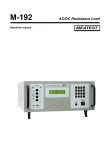
By pressing the TEST button the testing mode is called. The testing mode can be only
released, if the output terminal is disconnected (OUTPUT OFF). A LED diode above
TEST
the button will light up and the display will show ”t 0”. The required test number can be
set by the button under the digit. By pressing the TEST button once again the test is
started. Testing can be stopped by next pressing the TEST button. The device offers
the following tests:
TEST 0
finishing the testing mode
TEST 1
enables the functioning check of all display and indication units.
Particular segments and LED diodes are gradually lighted up.
TEST 2
enables checking of control buttons. After pressing any button,
the
display
shows
its
code.
Pressing
the
buttons
is
accompanied by an acoustic check. The figures below show the
button codes.
TEST
User's manual
8
MEATEST
M -150S Current Calibrator
OUTPUT
00
10
20
30
01
11
21
31
FREQUENCY MODE
02
12
22
32
03
13
23
33
43
53
64
74
MODE
72
72
63
REMOTE
61
FUNCTION
44
OUTPUT
55
62
75
TEST 3
enables to display and set up the GPIB instrument address. The
actual address is shown on the right display. The address value
can be changed by means of buttons placed under the right
display within the range from 0 to 30.
TEST 4
displays the serial number of the calibrator
TEST 5
Grounding of the L terminal can be adjusted during this test.
Adjusting is carried out with the last two keys of the keyboard for
setting current values. The display shows the existing state ”on
- oF”
TEST 6
unoccupied
TEST 7
calls the date of the last calibration. After completing a
calibration a new calibration date is recorded here.
TEST 8
setting the calibration code
(0000 to 19999). The code set
up implicitly is 0. Any calibrating code different from 0 can be set
only once. After setting any calibrating code different from 0, the
TEST 8 is no more accessible.
by pressing a key the display of calibrating jitter at a preset current value can be called
%SPEC
User's manual
9
MEATEST
M -150S Current Calibrator
on the B display.
Pressing the key enables the percentage setting of deviation (error)from the preset
ERR %
current value. The setting range is ± 5% of the preset value.
The CAL key enables access to the calibrating procedure. The calibration mode is
CAL
indicated by lighting of the LED diode above the key. The calibration mode is protected
against
encroachments by means of the calibrating code. For the calibration
procedure see the chapter 10.
By pressing the key, the forced control of the calibration supply is converted to
REM/LO
%SPEC
the local control from the front panel (on condition that the front panel is not
locked by a programme). The key is active only if the calibrator is in the remote
control mode through the GPIB bus. In the local control mode the button has
no other function. The LED diode above the button is only lighting if the device
is in the remote control mode.
FUNCTION
The EXT key is used for selection of the external input. Then the calibrator
EXT
ACI
%SPEC
works with the external voltage reference.
The ACI key is used for selection of the alternating current mode.
The DCI key enables selecting of the direct current mode.
DCI
OUTPUT
ON +
- by pressing the ON+ key the preset current is connected to the output terminal
of the calibrator in the positive polarity.
The connection is indicated by lighting a yellow LED diode above the key.
ON -
- by pressing the ON+ key the preset current is connected to the output terminal
OFF
of the calibrator in the negative polarity.
The connection is indicated by lighting a yellow LED diode above the key.
- by pressing the OFF key the preset current is disconnected from the output
terminal.
A DISPLAY
- displays the preset current value correct to four decimal places
User's manual
10
MEATEST
M -150S Current Calibrator
B DISPLAY
- displays the output current frequency, percentage balance of preset output value in ERR % mode,
specification referring to the preset value and other functions, see the chapter ”Calibration”.
POWER
- The power supply button. It enables connection of the device to the voltage supply.
EXTERNAL INPUT
The calibrator has two input terminals for connecting the external voltage reference.
H INPUT
input terminal (HIGH). The terminal is intended for connecting the signal conductor of
the external reference.
L INPUT
input terminal (LOW). The terminal is intended for connecting the common conductor
of the external reference.
Note:
The external input is connected by the L INPUT terminal with the potential of the
calibrator’s L OUTPUT terminal.
OUTPUT TERMINALS
The voltage supply has two output terminals and one terminal with the protective (guard) conductor
(GND) connected. All terminals are placed on the front panel.
H OUTPUT
- the output signal current terminal (HIGH).
CURRENT
The terminal is intended for connection of the signal current input of the checked
ammeter. The calibrator’s current output is led to this terminal
L OUTPUT
- the output current terminal of the common conductor (LOW).
CURRENT
The terminal is intended for connection of the common conductor (LOW) of the
checked ammeter current input.
GND
User's manual
- protective conductor terminal (instrument frame).
11
MEATEST
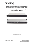
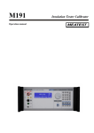
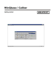
6.1.2
M -150S Current Calibrator
Rear Panel
The rear panel contains the socket for the mains voltage supply combined with the case for a cut-out
fuse and a connector for GPIB bus (IEC 625). The remaining surface of the back panel is filled with air
holes used for the forced ventilation of the calibrator inner space.
Explanation:
1 - air holes of switched supplies
2 - air holes of the current amplifiers
3 - connector of the GPIB bus
4 - mains voltage supply socket with the fuse housing
User's manual
12
M -150S Current Calibrator
1
2
3
4
MEATEST
User's manual
13
MEATEST
6.2
M -150S Current Calibrator
Starting the Device
Place the calibrator in a laboratory or in a room intended for its operation and connect it to the
mains. Make sure that the space near the ventilation holes is not covered or blocked. Poor ventilation
during operation, caused e.g. by blocking the inlet hole, can result in overheating of electronic
components that can damage the device.
Switch on the device by pressing the power button placed in the left part of the front panel.
After the device is switched on, the initial test of the calibrator is performed.
The test consists of:
- check of the display and indication units. After switching on all the units light up.
- check of the GPIB address. The display shows the actual calibrator address.
- internal memory checks (are not indicated)
After the test is completed, the following mode of the calibrator is set:
OUTPUT CURRENT
output value
10 A
FUNCTION
DCI
OUTPUT
OFF
6.3
Control of the Calibrator
6.3.1
Selection of Output Current Value
The output current value can be set up with buttons located under the A display by stepping
upward and downward. The setting range for setting up values within the 100 A range is following:
9
A to 100 A
User's manual
14
MEATEST
6.3.2
M -150S Current Calibrator
Frequency Setting
The frequency value can be set by pressing the FREQUENCY buttons located under the B
display, if the ACI function has been previously selected. The means of setting is similar to the method
of setting the output current value. Frequency can be set with two buttons by stepping upward and
downward. The display shows the selected frequency value.
6.3.3
Deviation Setting
After pressing the ERR% button, the calibrator enables to change current values in percentage
deviations from the preset value. The preset value is shown in the left A display and the percentage
deviation in the right B display. The deviation can be changed by pressing the buttons placed under
the B display The mode is suitable for calibration of analogue ammeters, where this mode enables
direct reading of errors of the calibrated instrument. This function cannot be used in the EXT mode.
6.3.4
Calling Calibrator Specification
The specifications corresponding to the preset output current value in the A display can be
called by pressing the SPEC% button. Then the calibration accuracy is displayed on the right B display.
Accuracy is not displayed in the EXT mode. The function cannot be used in the EXT mode.
6.3.5
Connection of Output Terminal
The output current can be connected to the output terminal by pressing the OUTPUT ON
button (indicated by a LED diode). The connection is always accompanied with delay. Signal cannot be
connected to the output terminal without a load connected. By pressing the OFF key the current is
disconnected from the output terminal. At the same time the yellow LED diode is turned off. If the
calibrator reports an error made by the user or the instrument (see the Chapter 6.4), the output
terminal is automatically switched off. Reconnection of the terminal is only possible after the cause of
the error is removed, by pressing the OUTPUT ON button.
Note: By pressing the ON key, the internal relay, which short-circuits the output terminals H OUTPUT
and L OUTPUT, is disconnected and the output current value is fluently increased as high as to the
preset value that is shown in the A display. Anytime during adjustment of the output current value, the
OFF function can be started.
By pressing the OFF key the preset value of output current is fluently lowered as low as to approx. 10
A. Then the internal relay, which short-circuits the output terminals H OUTPUT and L OUTPUT, is
User's manual
15
MEATEST
M -150S Current Calibrator
connected. During the OFF operation neither ACI and DCI functions can be changed nor the ON
function can be started.
For accurate calibration of DUT from the current output terminals, the load wouldn’t change its
impedance too quickly. This effect can also cause modulation of output current. This practically means
that the loads of current terminals must be properly connected and tightened under the terminals so
as the contact resistance cannot change more that by 5 % of the load value.
!!!CAUTION!!!
Before disconnecting the calibrator from the mains supply it is necessary to enter the OFF
function and wait until the LED diode located under this button is lighted up.
6.3.6
Tests
The tests are started by pressing the TEST button. The buttons placed under the display are
used for setting the test number. By pressing again the TEST button, the test number is confirmed.
The testing function is finished by pressing the TEST button. The meaning of particular tests is
mentioned in the Chapter 6.1.1.
6.4
Error Reporting
During control of the calibrator, the microprocessor checks the correctness of entered data. If
the entered data are incorrect or cannot be processed by the device, the calibrator displays the error
report to the user. The visual reporting on the display is accompanied by acoustic signalling .
Error Reporting Summary
User’s errors
Err. 00
Current overload of a current unit
Err. 01
Too high output voltage on the load (no load on terminals)
Err. 04
Attempt to recalibrate with output terminals turned off.
Err. 06
Attempt to recalibrate the device that has not been turned on minimally
30 minutes.
GPIB errors
Err. 10
Incorrect data format entered.
Err. 11
Incorrect command entered.
Err. 12
Listener is not connected.
Err. 13
Data out of reach of the instrument entered.
User's manual
16
MEATEST
M -150S Current Calibrator
Instrument errors
Err. 30
Error during data transmission between the floating and non-floating
parts of the instrument.
6.5
Err. 31
Error during recording data into EEPROM memory
Err. 32
Error during check of the EEPROM memory.
System Control via GPIB bus
The calibrator is equipped with the normalised GPIB bus. The system connector can be found
on the rear panel.
User's manual
17
MEATEST
M -150S Current Calibrator
The instrument can perform following functions:
SH1, AH1, T5, RL1, DC1
See the list of control commands in the table below:
Cx
AC/DC mode
C0 - alternating current
C1 - direct current
Ex
external reference mode
E0 - external input disconnected
E1 - external input connected
F
frequency
F - CR frequency
Ox
output
O0 - output disconnected
O1 - + output connected
O2 - - output connected
M
current amplitude
U - CR current
Vx
verification
V0 - current amplitude
V1 - frequency
V2 - status [CxExOx]
V3 - serial number
V4 - unoccupied
V5 - specification
The instrument can be programmed by the sequence of control codes A X A X A X . . . , where A is a
control code of the function and X is the function status.
Output Format of Values
If the V0 function is applied, the output data have the following format:
_ A X . X X X X E {+/-} X X A CR LF
If the V1 function is applied:
_ F X . X X X X E {+/-} X X H from CR LF
If the V2 function is applied:
_ C X E X O X CR LF
If the V3 function is applied:
_ V 1 5 0 X X CR LF
If the V5 function is applied:
_ E X X X . X X X % CR LF
Setting of Current Value
The format for value setting is as follows:
M . . . CR
(F . . . CR)
The control code is followed by a decimal number in the free format with an exponent or without it.
7.
Maintenance Instructions
User's manual
18
MEATEST
M -150S Current Calibrator
Except the button switches, power supply switch and ventilator, there are not any moveable
parts in the instrument and the instrument does not require any mechanical maintenance.
Calibrator Breakdowns
The electronic components underwent the artificial ageing by means of temperature cycling
during production and so no breakdowns should occur during operation. If after all any breakdown
occurs, it is recommended to proceed as follows:
1. If the testing procedure is not started and completed after the instrument is
switched on, check the fuse on the back panel. Unplug the mains before
unscrewing the fuse holder!
2. If the instrument reports the ERR 01 failure, check whether the calibrator is
not overloaded by the connected load.
If the breakdowns occurred during operation cannot be repaired by replacement of fuses, it is
necessary to consult with the manufacturer. The spare fuse is placed in the fuse case and it is
accessible after pulling out the plug-in part of the case.
8.
Calibration
8.1
Calibration Principle
The calibrator M-150S is a source of accurate DC and AC currents. The instrument
specification guarantees the compliance with parameters for the period of 12 months from the date of
last calibration or from the first calibration during production. The recommended recalibration interval is
12 months.
M-150S is equipped with the calibrating procedure that enables a simple recalibration. To
carry out the calibration doesn’t require setting of any mechanical setting unit (resistance or
capacitance trimmers) The calibration is carried out according to the prescribed procedure only by
entering data via the instrument keyboard. The calibrating procedure consists in setting the slope of
current range in the alternating current generating mode and in setting the slope and off-set in the
direct current mode. The recommended calibrating frequency is 60 Hz.
8.2
Calibration Procedure
To calibrate M-150S, the following instruments are required:
User's manual
19
MEATEST
M -150S Current Calibrator
1. Standard multimeter with the AC U accuracy at least of 0.03 % 40 to 120 Hz
with the DC U accuracy at least of 0.3 %
Range: from 10 to 200 mV
Recommended types: Datron 1271
Datron 1081
HP 3458A
2. Standard resistor 0.001 mOhm with the calibrating uncertainty lower than 0.02 % in the DC
frequency band up to 60 Hz
Recommended types: Tinsley 5686 0.001 Ohm (up to 150 Hz)
Burster 1281 0.001 Ohm
3. AC/DC voltage calibrator to 10 V
Recommended types: Meatest M-130
Datron 9100
Fluke 5500
Carry out the calibration only after the thermal conditions of the calibrator have been stabilised at least
30 minutes after it was switched on.
8.2.1
Calibrating Code
Access to the calibrating procedure is protected by calibrating code. The manufacturer supplies the
instrument with the calibrating code equal 0. This code is also shown on the display. The user can set
up a five-digit code that makes it possible for him to enter in the calibrating procedure only once. When
non-zero calibrating code was set, the user neither can more change this code nor read it from the
instrument. He should consider properly whether to use this function or not and record the code.
Unlocking the code can be done by the manufacturer only. The TEST 8 is used for setting up the code.
Coding Procedure:
1) Press the TEST button, select the TEST 8
2) Press again the TEST button. Right display will show ”0”. Maximally a five-digit code can be set by
means of the buttons under the right display. This code must be recorded.
3) Press the TEST button and the instrument will be returned to the previous state. Thus the coding
procedure is completed
User's manual
20
MEATEST
M -150S Current Calibrator
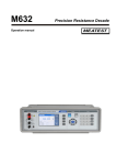
8.2.2
Calibration of Current Range
1. Connect the current terminals of the standard resistance to the calibrator output terminals; connect
standard multimeter to the voltage terminals of the standard resistance (see the figure).
Calibration of DC current range
Set the calibrator as follows:
FUNCTION
OUTPUT
OUTPUT VALUE
TEST 5
DCI
OFF
10 A
grounding of the output terminal ON
2. Select the measuring mode DC - U on the standard multimeter. Switch output terminals ON.
3. Press the CAL button. Set the code protecting the calibrating data against undesirable
manipulation by pressing the buttons under the right display. After the code is set, press the CAL
button. If the code is incorrect, the instrument is turned back on the previous mode. If the code was
correctly set, the red LED diode above the CAL button will light up.
4. Press the CAL button on M150S. The display B will show OFS. 0, the left A display will show the
correcting value of previous calibration. Set by pressing the buttons under the left display such data
so as the multimeter can indicate the 0 V value according the table POSITIVE OFF-SET
CORRECTIONS.
5. Press the CAL button. The right display will show -OFS, the left display will show the negative
correcting value of the previous calibration. By pressing the buttons under the left display set such
value that standard multimeter indicate 0 V value in the range according the table NEGATIVE
OFFSET CORRECTIONS.
6. Press the CAL button. The right display will show 100.00, which means calibration in the point 100
A of the 100 A range. Set the value of 100 x RN on the multimeter by pressing the buttons under the
left display. The RN value is the calibrating value of the standard resistance at DC current. The set
value tolerance is given in the table POSITIVE SLOPE CORRECTIONS. The value set on the
calibrator, has no direct numerical connection with the calibrated current!
7. Press the CAL button. The right display will show the value of -100.00, which means calibration of
the point -100 A of the 100 A range. Set the value of 100 x RN on the standard multimeter by
pressing the buttons under the left display. The RN value is the calibrating value of the standard
resistance at DC current. The set value tolerance is given in the table NEGATIVE SLOPE
CORRECTIONS. The value set on the calibrator has no direct numerical connection with the
User's manual
21
MEATEST
M -150S Current Calibrator
calibrated current!
Calibration of AC current range
8. Press the CAL button. Now the calibrator mode can be set again. Press the OUTPUT OFF button,
select the ACI mode and set the frequency of 60 Hz. Switch standard multimeter to the AC voltage
measuring mode and press the OUTPUT ON button.
9. Press the CAL button. The right display will show the value of 100.00, which means calibration point
100 A AC on the 100 A range. Set the value of 100 x RN on the multimeter by pressing the buttons
under the left display. The RN value is the calibrating value of the standard resistance at the AC
current 60 Hz. The set value tolerance is given in the table SLOPE CORRECTIONS. The date set
on the calibrator has no numerical connection with the calibrated current!
User's manual
22
MEATEST
M -150S Current Calibrator
10. Press following buttons: CAL, OFF, EXT, ON+ . The A display will show - E -.
11. Press the CAL button. The right display will show the value of 100.00, which means calibration
point 100 A on the 100 A range. Now connect the external DC reference in the positive polarity with
the input terminals H INPUT (+) and L INPUT (-) e.g. from the DC calibrator. Set the value of +10 V
on the external reference. Set the value of 100 x RN on the multimeter by pressing the buttons
under the left display. The RN value is the calibrating value of the standard resistance at DC current.
The set value tolerance is given in the table POSITIVE SLOPE CORRECTIONS.
12. Press the CAL, OFF and ON- buttons on M150S.
13. Press the CAL button. The right display will show the value of -100.00, which means calibration
point -100 A on the 100 A range. Now connect the external reference in the negative polarity to the
input terminals H INPUT (-) and L INPUT (+) e.g. from the DC calibrator. Set the value of -10 V on
the external reference. Set the value of 100 x RN on the multimeter by pressing the buttons under
the left display. The RN value is the calibrating value of the standard resistance at DC current. The
set value tolerance is given in the table NEGATIVE SLOPE CORRECTIONS.
User's manual
23
MEATEST
M -150S Current Calibrator
14. Press the CAL button. Now the calibrator mode can be set again. Press the OUTPUT OFF button,
select the ACI mode. Set the external reference voltage 10 V AC on AC voltage standard calibrator
and set the external reference frequency f ext in the range from 40 Hz to 120 Hz. Switch the
standard multimeter to the AC voltage measuring mode and press the OUTPUT ON button.
15. Press the CAL button. The right display will show the value of 100.00, which means calibration point
100 A on the 100 A range. The left display is showing -E-. Set the value of 100 x RN on standard
multimeter by pressing the buttons under the left display. The RN value is the calibrating value of the
standard resistance at AC current on frequency f ext. The set value tolerance is given in the table
SLOPE CORRECTIONS.
16. Press the CAL, OFF and EXT buttons. Now the calibrator is set in mode before calibration. After
the calibration is completed, press the TEST button, set 7 on the left display and record the date of
calibration by means of buttons under the display. After the date is recorded, press again the TEST
button. The TEST light indication will be turned off as well as the MODE CAL indication. The
calibration is completed.
Table of Calibrating Values Tolerance
range
100 A
DC value
AC
0 ± 10 mA
100 A ± 20 mA
100 A ± 50 mA
- 100 A ± 20 mA
100 A ext.
100 A ± 20 mA
100 A ± 50 mA
- 100 A ± 20 mA
User's manual
24
MEATEST
Note:
M -150S Current Calibrator
The previous values are set on the standard multimeter as voltage with the converting constant
of the standard resistor RN.
To review the procedure, the following table summarises the calibrating procedure, recorded displayed
indications and pressing the buttons
Button
function
I. Selection of calibrating mode
CAL
calling CAL function
setting the calibrating code
CAL
calling the calibration
II. Calibration of the range 100 A DC
RANGE 100A
setting
ON+
connection of output terminals
CAL
correction of + DC offset
”
CAL
correction of - DC offset
”
CAL
setting the slope 100 A
”
CAL
setting the slope -100 A
”
CAL
end of the calibration ± 100 A
OFF
disconnection of terminals
III. Calibration of the range 100 A AC
RANGE 100A
setting
ON+
connection of output terminals
CAL
setting the slope 100 A
”
CAL
end of the calibration 100 A
OFF
disconnection of terminals
IV. Calibration of the range 100 A +DC external input
RANGE 100A
setting
ON+
connection of output terminals
CAL
setting the slope 100 A
”
CAL
end of the calibration + 100 A
OFF
disconnection of terminals
User's manual
left
display
right
display
XYZ
XYZ
XYZ
0
*****
XYZ
100.00
100.00
2
*****
-2
*****
55000
*****
55000
*****
100.00
Note
LED
OFS. 0
OFS. 0
OFS. 0
OFS. 0
100.00
100.00
-100.00
-100.00
cor.
zero
OFF
100.00
100.00
55000
*****
100.00
60
60
100.00
100.00
OFF
-E-E55000
****
-E-
100.00
100.00
OFF
25
MEATEST
M -150S Current Calibrator
V. Calibration of the range 100 A -DC external input
RANGE 100A
setting
ONconnection of output terminals
CAL
setting the slope 100 A
”
CAL
end of the calibration - 100 A
OFF
disconnection of terminals
VI. Calibration of the range 100 A AC external input
RANGE 100A
setting
ONconnection of output terminals
CAL
setting the slope 100 A
”
CAL
end of the calibration 100 A
OFF
disconnection of terminals
VII. Closing the calibrating cycle
TEST
calling the TEST function
setting TEST 7
setting the calibration data
TEST
Closing the calibrating cycle
(LED CAL is turned off)
Note:
-E-E55000
****
-E-
-100.00
-100.00
OFF
-E-E55000
****
-E-
-F-F100.00
100.00
-FOFF
t0
t7
t7
MM.RR
**.**
origin.
new
The correcting values 550.00 are related to the first calibration. During recalibration, the real
previous correcting values will appear in these positions.
XYZ is the state of the display during the previous step.
8.3
Check of Parameters
To check the parameters, the following instruments are required:
1. Standard multimeter with the accuracy
AC U at least of 0.03 % in range 40 to 120 Hz
DC U at least of 0.03 %
Range of AC/DC voltage: from 10 to 200 mV
types:
Datron 1281
Datron 1081
HP3458A
User's manual
26
MEATEST
M -150S Current Calibrator
2. Resistance standard nominal value 0.001 .Ohm with uncertainty of calibration value better than 0.03
% in frequency range 0 to 60 Hz,
types:
Tinsley 5686 0.001 Ohm
BURSTER 1281 0.001 Ohm
The check is carried out after the temperature mode of the calibrator has been stabilised, at least 30
minutes after it was switched on.
2. Counter with period function and with accuracy at least 0.01 % in the range up to 120 Hz.
types:
TESLA BM526
BM640
3. Distortion meter for frequency range to 120 Hz
types:
TESLA BM 543
HP 8903A
8.3.1
Check of Current Ranges
1. Connect the current terminals of the standard resistance to the calibrator output terminals and
connect the multimeter to the voltage terminals of the standard resistance.
Set the calibrator as follows:
FUNCTION
DCI
OUTPUT
OFF
OUTPUT VALUE
100 A
TEST 5
grounding of the output terminal ON
2. Select the measuring mode DC U on the multimeter and OUTPUT ON+ on the calibrator.
3. Check whether the measured value is in compliance with the tolerance mentioned in the table.
4. Press ON- and do again the instructions in paragraphs 1 to 3
Switch off the calibrator output OFF
User's manual
27
MEATEST
M -150S Current Calibrator
5. Set the current calibrator.
FUNCTION
ACI
FREQUENCY
60 Hz
OUTPUT
OFF
OUTPUT VALUE
100 A
6. Select the measuring mode AC U on the multimeter and OUTPUT ON+ on the calibrator.
7. Check whether the measured value is in compliance with the tolerance mentioned in the table.
8. Repeat instructions 1 to 7 for the mode DCI EXT and ACI EXT.
9. Switch off the calibrator output OUTPUT OFF.
function
range
DCI
+100 A
- 100 A
ACI
100 V
DCIEXT
+100 A
- 100 A
ACIEXT
100 V
Table of tolerance values.
8.3.2
tolerance [ mV ]
99.8 x RN - 99.8 x RN 99.8 x RN 99.7 x RN - 99.7 x RN 99.6 x RN -
100.2 x RN
-100.2 x RN
100.2 x RN
100.3 x RN
-100.3 x RN
100.4 x RN
Check of non-linear distortion
1. Connect to the output terminals of M-150S resistance load, the value of which must be sufficient for
reaching the voltage on the load of about 0.5 Vef. For this reason you can also use the standard
resistor 0.001 Ohm, which shall be connected with longer cables with approx. resistance 0.005
Ohm. Connect the distortion meter to the H OUTPUT and L OUTPUT.
FUNCTION
ACI
FREQUENCY
60 Hz
OUTPUT
OFF
OUTPUT VALUE
100 A
2. Press OUTPUT ON and measure the non-linear distortion of the generated signal.
3. The value of distortion must not exceed 0.03 %
4. Switch off the calibrator output OUTPUT OFF
8.3.3 Frequency Check
1. Set the counter in the period measuring mode and connect it to the output terminals H OUTPUT and
L OUTPUT. Connection of the load is the same as during distortion metering.
User's manual
FUNCTION
ACI
FREQUENCY
50 Hz
OUTPUT
OFF
OUTPUT VALUE
100 A
28
MEATEST
M -150S Current Calibrator
2. Press OUTPUT ON+ and measure the output signal period. This must not exceed the range from
19.998 ms to 20.002 ms.
User's manual
29
MEATEST
M -150S Current Calibrator
CAUTION
1) Never switch off the calibrator with the output terminals switched on (ON mode) by means of the
power button (POWER).
2) Switch off the current calibrator by pressing the power button (POWER) only after the OUTPUT OFF
button was pressed and after the time-out of about 20 second.
3) Don’t switch on the calibrator by means of the power button until the time-out between the last
switch-out and the next switch-on is longer than cca. 20 seconds.
User's manual
30