1
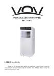
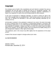
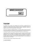
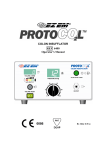
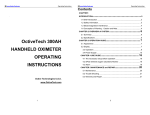
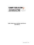
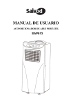
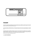
VITAL SIGNS MONITOR INSTRUCTION MANUAL MODEL: VI-200A Copyright Our company owns all rights to this unpublished work and intends to maintain this work as confidential. We may also seek to maintain this work as an unpublished copyright. This publication is to be used solely for the purpose of reference, operation, maintenance, or repair of our equipment. No part of this can be disseminated for other purposes. In the event of inadvertent or deliberate publication, we intend to enforce its right to this work under copyright laws as a published work. Those having access to this work may not copy, use, or disclose the information in this work unless expressly authorized by our company. All information contained in this publication is believed to be correct. We shall not be liable for errors contained herein nor for incidental or consequential damages in connection with the furnishing, performance, or use of this material. This publication may refer to information and protected by copyrights or patents and does not convey any license under the patent rights of our company, nor the rights of others. We do not assume any liability arising out of any infringements of patents or other rights of third parties. The illustrations used in this manual may differ slightly from the appearance of the actual product. Content of the manual is subject to changes without prior notice. ALL RIGHTS RESERVED CONTACT Venni Instruments, Inc. 535 Broadhollow Road Suite B24 Melville, NY 11747 Telephone: 1-631-223-4685 Fax: 1-631-393-2775 Email: [email protected] Web: http://www.vennimed.com - 2 - CONTENT CHAPTER 1 Introduction...................................................................................................5 1.1 About the Manual...................................................................................................5 1.3 Safety Information .................................................................................................5 1.4 Explanation of Symbols........................................................................................7 1.5 Description of Abbreviation .................................................................................7 1.6 Intended Use ..........................................................................................................8 CHAPTER 2 Overview Of Monitor.....................................................................................8 2.1 Special Feature ......................................................................................................8 2.2 Appearance of Monitor .........................................................................................8 2.3 Specification ........................................................................................................13 CHAPTER 3 Patient Safety..............................................................................................14 3.1 Environment.........................................................................................................15 3.2 Grounding ............................................................................................................15 CHAPTER 4 Getting Started............................................................................................15 4.1 Unpacking and Inspection..................................................................................15 4.2 Connect the Power Cables .................................................................................15 4.3 Power on the Monitor..........................................................................................16 4.4 Connect with Patient Sensors ............................................................................16 4.5 Check the recorder..............................................................................................16 CHAPTER 5 Measuring screen and Main menu ............................................................16 5.1measuring screens...............................................................................................16 5.2 Main menu............................................................................................................18 CHAPTER 6 Date & Time, ID Settings ............................................................................18 6.1.Time settings .......................................................................................................19 6.2. ID number setting ...............................................................................................19 CHAPTER 7 Take a Measurement ..................................................................................20 7.1 SpO2 and PR measurement ................................................................................20 7.2 NIBP Monitoring and precautions......................................................................22 7.2.1 Introduction.......................................................................................................22 CHAPTER 8 Data Management.......................................................................................25 8.1 SpO2&PR Record Review....................................................................................25 8.2 SpO2 Trend Review..............................................................................................26 8.3 PR Trend Review .................................................................................................27 - 3 - 8.4 NIBP Record Review ...........................................................................................27 8.5 NIBP Trend Review..............................................................................................27 8.6 Erase Data ............................................................................................................28 CHAPTER 9 NIBP Measurement Set...............................................................................28 CHAPTER 10 Alarm Set...................................................................................................29 10.1 Alarm priority .....................................................................................................29 10.2 Alarm set ............................................................................................................30 CHAPTER 11 Real Print Set(Optional) ...........................................................................31 CHAPTER 12 Network Set(Optional)..............................................................................32 CHAPTER 13 System Set ................................................................................................32 CHAPTER 14 System Configuration ..............................................................................33 CHAPTER 15 NIBP Operation .........................................................................................34 CHAPTER 16 System Info ...............................................................................................34 CHAPTER 17 Trouble shooting ......................................................................................34 CHAPTER 18 Maintenance And Cleaning ......................................................................35 18.1 Maintenance.......................................................................................................35 18.2 Warranty and Repair..........................................................................................37 Appendix ..........................................................................................................................38 - 4 - CHAPTER 1 Introduction 1.1 About the Manual Before using the vital signs monitor, the user must carefully read this manual so that the user can operate the monitor properly and make it reach the specific safety standard and performance index. This manual explains how to set up and use the monitor. Important safety information relating to general use of the monitor appears after this introduction. Other important safety information is located throughout the text where appropriate. Note: There requires no routine calibration, safety maintenance or in-service during the monitor’s life. 1.2 Contraindications Active patients. Intravascular dyes such as indocyanine green or methylene blue. Significant levels of dysfunctional hemoglobins (such as carbonxy-hemoglobin or methemoglobin). The presence of high ambient light. Shield the sensor area (with a surgical towel, or direct sunlight, for example) if necessary. Venous pulsations may cause erroneous low readings(e.g. tricuspid value regurgitation) Venous congestion may cause under reading of actual arterial oxygen saturation. Therefore, assure proper venous outflow from monitored site. Sensor should be not below heart level ( e.g. sensor on hand of a patient in a bed with arm dangling to the floor) Avoid placing the sensor on any extremity with an arterial catheter, intravascular line or blood pressure cuff. Do not use the monitor when the patient is in cardiac arrest or is in defibrillation. Excessive caution with low perfused patient; skin erosion and/or pressure necrosis may occur. 1.3 Safety Information Warnings alert the user to potential serious outcomes, such as death, injury, or adverse events to the patient or user. Cautions alert the user to excess care necessary for the safe and effective use of the monitor. Notes contain important information that may otherwise be overlooked or missed. Warnings The medical equipment must be manipulated by personnel who have already got relative training of operation. Do not use the monitor in a MRI or CT environment The monitor must be able to measure the pulse properly to obtain an accurate SpO2 measurement. Verify that nothing is hindering the pulse measurement before taking the SpO2 measurement. Explosion hazard: Do not use the monitor in the presence of flammable anesthetic or in an explosive atmosphere. Do not make any clinical judgments based solely on the monitor. The monitor is intended only as an adjunct in patient assessment. It must be used in conjunction with clinical signs - 5 - and symptoms. Prolonged use or the patient’s condition may require changing the sensor site periodically. The site must be checked at least every four hours to ensure adequate adhesion, circulation, skin integrity and correct optical alignment. If the circulatory condition or skin integrity is compromised, the sensor should be applied to a different site. Use only the battery, power cable and accessories appointed by manufacturer, as other accessories may cause improper performance or dangers. Connect the monitor to a three-wire, grounded, hospital-grade receptacle if necessary.. By replacing the fuse, please use the safety fuse of the same type and rated fuse. When connecting the monitor to any instrument, verify proper operation before clinical use. Refer to the other device’s manual for full instructions. Accessory equipment connected to the monitors data interface must be certified according to IEC Standard 60601-1 for electro medical equipment. All combinations of equipment must be in compliance with IEC Standard 61601-1-1 systems requirements. To avoid potentially hazardous leakage currents, always check the summation of leakage currents when several item of equipment are interconnected. Before use the equipment, inspect whether all the cables are in good condition, the damaged cables and connectors must be replaced. Operator should examine whether the system is in correct working state and operating condition. As with all medical equipment, carefully route patient cabling to reduce the possibility of patient entanglement or strangulation. Do not use a tape to secure the sensor to the site; this can restrict blood flow and cause inaccurate readings. Use of additional tape can cause skin damage or damage the sensor. Dispose of the device and its accessories according to applicable local regulations. To avoid an electrical hazard, never immerse the unit in any liquid or attempt to clean it with liquid cleaning agents. Always disconnect monitor from AC Main Power before performing cleaning of maintenance. If the monitor becomes accidentally wet during use, discontinue operation of the monitor until all affected components have been cleaned and permitted to dry completely. Contact our local representative if additional information is required. The signal output part can be only connected to the computer complying with the requirements of IEC60950. Cautions! Do not sterilize by irradiation, steam, autoclave or ethylene oxide. Operation of the monitor may be affected by the use of an electrosurgical unit (ESU). The system may not conform to all performance specifications if stored or used outside the environmental specification identified in specification. Alarm must be set up according to different situation of individual patient. Make sure that audio alarm can be activated when alarm occurs. Do not only depend on the alarm system, the doctor and nurse will not draw attention when an alarm turn down or turn off. Single-use accessories should never be reused. If the accuracy of any measurement does not seem reasonable, first check the patient’s vital signs by alternate means and then check the monitor for proper functioning. - 6 - For proper equipment maintenance, perform the service procedures at the recommended intervals as described in the manual. If the monitor needs to be used continuously long-term, please note to connect the monitor with the main power supply by the alarm of battery, otherwise, the monitor will automatically shut down, which leads to the break-off of the monitoring. The monitor can monitor only one patient synchronously. Do not place the monitor in any position that might cause it to fall on the patient. Do not lift the monitor by the power supply cord or patient connections. As to the other points for attention, please carefully read the relevant chapter in this instruction. FEDERAL LAW (U.S.A) restricts this device to sale by or on the order of a physician. 1.4 Explanation of Symbols Power on/off button Type BF applied part Alarm sound off indicator Alarm sound on indicator Battery power indicator Alarm Inhibition indicator Fuse Up/increase button USB transmission state indicator; When it is colored , it indicates USB transmission is activated;While it is grey,it indicates the USB transmission is off. NET state indicator; when it is colored, it indicates Network function is activated, While it is grey,it indicates Network function is off. Pulse beep indicator; when it is colored, it indicates the beeper on, while it turns to grey, it indicates the beeper is off. Print icon;When print is set on, it is colored, while off, t is grey. Alarm inhibition/off button or Return button Down/decrease button Confirm button Equipotential terminal 1.5 Description of Abbreviation SpO2: PR: NIBP: Arterial oxygen saturation Pulse rate Non-invasive measurement of blood pressure - 7 - grounding SYS: DIA: MAP Systolic pressure Diastolic pressure Mean arterial pressure 1.6 Intended Use The vital signs monitor is a portable device indicated for use in non-invasively measuring and displaying functional oxygen saturation of arterial haemoglobin (SpO2), pulse rate(PR), Non-invasive measurement of blood pressure(NIBP) of adult and pediatric patients in hospitals, medical facilities, and sub-acute environments. The vital signs monitor is intended for spot-checking and/or continuous monitoring of patients. CHAPTER 2 Overview Of Monitor 2.1 Special Feature Portable, compact structure LED & LCD display Display: SpO2, Pulse rate, Pulse bar, SpO2 plethysmogram, NIBP data and so on Convenient clinical operation Up to 99 patients information and 72-hour records storage Visible & 3-level audio alarm Battery-low indication Built-in rechargeable battery or AC power Built-in thermal recorder(optional) Probes suitable for adult Oscillometry method to measure NIBP and one hose cuff system. Probes suitable for pediatric or neonatal(optional) 2.2 Appearance of Monitor 2.2.1 Front panel - 8 - Fig. 1 Description of Fig.1: 1. LCD displaying screen: Display SpO2 waveform, Pulse rate, Pulse amplitude indicator (blip bar), NIBP status indicator, USB indicator, the date & time, alarm limits, system icon and ID number. 2,8. Pressure unit indication lamp: Indicate the use of mmHg or kPa when the corresponding indication lamp on. 3,4,7. LED displaying screen: Display SYS, DIA, MAP of Non-invasive measurement of blood pressure(NIBP). 5. SpO2 sensor port 6. NIBP cuff port 9.NIBP button: Press this button in any time, the cuff starts inflating and press it again, the cuff switches to deflate. 10. Down button: Press this button you can select different item and decrease the number. 11. CHG indication lamp: Battery charge indicator. If the battery is charging, the lamp will flash. When the battery is charged to full, the lamp will off. 12. Power button: Press the button for 3 seconds you can power on the monitor, or press the button for 4 seconds you can turn off the monitor. 13. Internal battery indication lamp: Battery power enough: The lamp is always on. Battery low: The lamp will be flashing. Without battery: The lamp will be closed. 14. UP button: Press this button you can select different items and increase the number. 15. MENU&OK button: Press this button to confirm your setting and enter the menu submenu. 16. Alarm silence/Return button: ONLY in the measuring screen, Press this button to silence the audio alarm for 2 minutes, and repress to restore the audio alarm; Press it for over 2 seconds to turn off the audio alarm and repress it for over 2 seconds to restore the alarm. In main menu or submenu, press this button to return to the previous screen. 2.2.2 Rear panel - 9 - Fig. 2 Description of Fig.2: 1 USB Interface: The monitor can be used as the USB device(The function is reserved.). 2 NET: The NET socket is connected with the center monitor system of our company(The function is reserved). 3 I/O:for programme upgrade(The function is reserved.). 4 Speaker 5 Power socket: AC Power supply socket. 6 Ground terminal 2.2.3 Battery installation Fig.3 Description of figure 3: 1— Fixing hole of fixing screw for fixing battery cover. 2,3,4,5—Electrodes for battery. 6—Battery cover. Unscrew the fixing screw in the battery cover of the monitor bottom panel, open the battery cover, and then place the battery into the battery box with the polarity correctly. The battery is shown in the fig.4. Make sure that the poles of the battery are playing as the following position: 2 to 2’, 3 to 3’;4 to 4’, 5 to 5’. - 10 - Fig. 4 Notes: Make sure that the polarity of the battery is correctly inserted. Otherwise the unit cannot operate normally. If the monitor is not used for a long time, please charge and discharge the Ni-MH battery thoroughly once a month. If the battery low indication icon displays during measuring, please connect the monitor to AC power socket timely, avoiding the current measuring is affected. Warning! Do not use the battery not appointed by our company. 2.2.4 Ground wire connection Connect the monitor to the ground system with ground wire (refer to Fig.5), as the following steps: Firstly, plug the part 1 to the monitor’s grounding terminal as Fig.6 shown. Fig.5 Fig.6 Fig.7 Secondly, press the clap on the other terminal of the ground wire to connect with the user’s ground system. Refer to figure 7. 2.2.5 Printer (Optional) The monitor can print the stored records and SpO2 waveforms with the configured SP-B6J printer. - 11 - Fig.8 Description of Fig.8: 1—Open button, pull the jut of cassette door, you can open the paper cassette door. 2—No paper indicator, the lamp will be lighted when there is no paper. 3—Printer power indicator, when the printer is printing records the lamp will be lighted. 4—Output of printing paper. Paper replacement Note : Record paper requirement Only standard 50(+0/-1) mm thermosensitive record paper can be used, otherwise the recorder may not function, the recording quality may be poor, and the thermosensitive print head may be damaged. Steps for paper replacement: 1. Press the open button as the Icon indication and then pull the paper cassette door towards you until it is completely open. 2. Remove the spent paper core. 3. Place a new roll of paper into the paper cassette door with a few inches of paper being unrolled. And then push slightly the roll of paper to the paper cassette (refer to the Fig.10). Ensure proper orientation of paper roll. Fig.10 4. Close the paper cassette door with a few inches of paper being kept outside of the door. NOTE When the recorder is working, the record paper goes out steadily. Do not pull the paper, or the recorder may be damaged. Do not operate the recorder without record paper. Make sure that the paper surface with the heat sensitive material towards to the heat sensitive - 12 - printing head. 2.3 Specification Power supply Main power Internal power Rated power input Fuse 100-230V AC 7.2V DC Less than 45VA 250V I max 1 A Environment The operation environment should comply with the following conditions: Operating Temperature: 5℃ to 40℃ Relative Humidity: ≤ 80%, non-condensing Standard Atmosphere Pressure : 86kPa~106kPa The transport and storage environment should comply with the following conditions: Storage Temperature: -20℃ to 55℃ Relative Humidity: 0 to 93%, non-condensing Standard Atmosphere Pressure : 50kPa~106kPa Display Type: LCD & LED Displayed Parameters Alarms: Pulse & SpO2 NIBP High and low limits selectable on patient parameters Pulse Rate, SpO2 plethysmograph, and oxygen saturation of blood hemoglobin SYS, DIA, MAP SpO2 Display range Measurement Range Accuracy LED Specifications Display Update Resolution 0 to 100% 70 to 100% 80-100%:±2%; 70-79%:±3%; 0-69% : Unspecified Wavelength Radiant Power 660±3nm RED 1.8mW 940±10nm IR 2.0mW <5s 1% Pulse Rate - 13 - Measurement Range 30 to 235bpm Display Range 0 to 254bpm Resolution 1bpm Accuracy 30-100, ±2bpm; 101-235±2%;0-29 Unspecified NIBP measurement Measurement Range SYS DIA MAP overvoltage protection of software overvoltage protection of hardware Resolution Leakage rate Pediatric 30-135 15 -110 20 -125 150mmHg Adult 30 -255 15 - 220 20 -235 280mmHg 145 5mmHg 280 10mmHg 1mmHg Less 6 mmHg/min Alarm Setting Range Parameters Upper alarm range Low alarm range SpO2(%) 71-100 70-99 PR (bpm) 31-254 30-253 SYS (bpm) 61-255 60-220 DIA (bpm) 31-220 30-180 MAP (bpm) 31-220 30-200 Outline Dimension 296mmX166mmX96mm Weight 1.8kg(including the battery) Classifications The device is BF type. Note: the device might not meet its performance specifications if stored or used outside the manufacturer's specified temperature and humidity ranges. CHAPTER 3 Patient Safety The vital signs monitor is designed to comply with the International Safety requirements for medical electrical equipment. - 14 - 3.1 Environment Follow the instructions below to ensure a completely safe electrical installation. The environment where the Monitor will be used should be reasonably free from vibration, dust, corrosive or explosive gases, extremes of temperature, humidity, and so on. For a cabinet mounted installation, allow sufficient room at the front for operation and sufficient room at the rear for servicing with the cabinet access door open. The Monitor operates within specifications at ambient temperatures between 5℃ and 40℃. Ambient temperatures that exceeding these limits could affect the accuracy of the instrument and cause damage to the modules and circuits. Allow at least 2 inches (5cms) space around the instrument for proper air circulation. Note : Make sure that during operation, the instrument is free of condensation. Condensation can form when equipment is moved from one building to another, thus being exposed to moisture and differences in temperature. 3.2 Grounding To protect the patient and hospital personnel, the cabinet of the monitor must be grounded. Accordingly, The Monitor is equipped with a detachable 3-wire cable which grounds the instrument to the power line ground (protective earth) when plugged into an appropriate 3-wire receptacle. If a 3-wire receptacle is not available, consult the hospital electrician. If the capacity of the protective ground wires is in doubt, the equipment must be operated with internal power supply. CHAPTER 4 Getting Started NOTE To ensure that the monitor works properly, please read Chapter 3, and follow the steps before using the monitor. 4.1 Unpacking and Inspection Open the package and take out the monitor and accessories carefully. Keep the package for possible future transportation or storage. Check the components according to the packing list. Check for any mechanical damage. Check all the cables, modules and accessories. If there is any problem, contact the distributor immediately. 4.2 Connect the Power Cables Connection procedure of the AC power cable: Make sure the AC power supply complies with following specification: 100-230 (VAC), 50/60 (Hz). Ensure that the AC outlet is properly grounded. - 15 - ⑴ Apply the power cable provided with the monitor. Plug the power cable into the power socket on the rear panel. ⑵ Connect the other end of the power cable to a grounded 3-line power output. NOTE Connect the power cable to the jack special for hospital usage. The battery needs to be charged after transportation or storage. If the power supply is not properly connected before turning on the monitor, it may not work properly because of insufficient power. Connect the main power supply to charge the battery. 4.3 Power on the Monitor After the probe is connected to its input cables, turn the monitor on by momentary pressure on the front-panel POWER button for 3 seconds. As audible beep feedback after pressing, the monitor is initiated. NOTE Check for all the functions that may be used to monitor and make sure that the monitor is in good status. The battery must be recharged to the full electricity after the battery low indicator appears. It is suggested to recharge the battery to the full electricity after each use of monitoring so as to reserve sufficient power in battery. WARNING If any sign of damage is detected, do not use it on any patient. Contact the biomedical engineer in the hospital or the distributor immediately. 4.4 Connect with Patient Sensors Connect the probe to the monitor (refer to 7.1 of chapter 7). 4.5 Check the recorder If your monitor is equipped with a recorder, open the recorder door to check if paper is properly installed in the output slot. If no papers present, do not press “ PRINT” function button. CHAPTER 5 Measuring screen and Main menu 5.1 measuring screens 5.1.1 Press the button for about 3 seconds to turn the monitor on, one of the following - 16 - measuring screens will display. Fig.11(1) Fig.11(2) Description of Fig.11(1) &(2): 1: The current date and time:2008-08-25 18:00; Silence audio alarm indicator :the current audio alarm status is on. Battery power indicator. 2: The current system status in fig.11: USB function indicator status:On Net function indicator status:On Print indicator status:the current status is on printing Pulse beep sound status indicator :On ID number: the current ID is 99. Bed number: the current bed number is 255. 3: Display the current measuring information of user NIBP measuring mode:the current mode is Auto and the auto mode cycle is 120 minutes. Patient type:Pediatric and the initial pressure is 70 mmHg. Remaining time for next pressure measurement in Auto mode:50 minutes NIBP measuring mode:Auto Patient type:Pediatric Remaining time for next pressure measurement in Auto mode:50 minutes - 17 - 4: The trend graphic of SpO2 in Fig.11(1); The list of the 7 NIBP records lastly measured in Fig.11(2). 5: Display of SpO2 alarm limits,PR alarm limits indication, and measurement information. The current SpO2 alarm limits: Upper alarm: 100; Lower alarm: 95. The current PR alarm limits: Upper alarm: 120; Lower alarm: 60. The current measurement status:”SpO2 measuring…” . Pulse bar. 5.2 Main menu 5.2.1 Menu 1 In measuring screen,short press the button for about 1 second to enter into menu 1, and press the button and button to look through the items. Please refer to Fig12. Fig.12 5.2.2 Menu 2 In measuring screen,press the then press the button and button for over 2 seconds to enter into menu 2 and button to look through the items. Refer to Fig.13. Fig.13 CHAPTER 6 Date & Time, ID Settings The Monitor features flexible configurations. You can configure various aspects of the monitor, including TIME, ID number, printer and so on. Always set the date and time before using the unit for the first time. Set different ID numbers for different user. Check whether the date and time are correct before using the unit, reset them if necessary. The date and time are important indicators when a measurement is taken. - 18 - 6.1. Time settings After entering into menu 2, press the the button to select “ Date And Time” item and press button to confirm your selection, you will see the following picture. Fig.14 Press the button and button to select the different data items, and press the to enter the selected item. Then increase or decrease the data by pressing the button and press the button to confirm your setting. Press the or the button to return to the previous screen. The setting ranges of the date and time are as follows: Year: 2000-2020 Month: 1-12 Day: 1-31 Hour: 0-23 Minute: 0-59 Second: 0-59 6.2. ID number setting After entering into menu 1, press the press the button to select “ Patient Info Set” item and button to confirm your setting, (refer to the Fig.15) Fig.15 Press the pressing or button to set the suitable ID number, and confirm your selection by button. Press the button to return to the previous screen. The setting - 19 - range of the ID number is 1~99. CHAPTER 7 Take a Measurement 7.1 SpO2 and PR measurement After the time and the ID number settings, connect the sensor and take a measurement according to the following pictures: Firstly, select the suitable sensor in terms of type and dimension; secondly, connect the sensor with the monitor (refer to fig.16). Clip the sensor to the rational position of the patient finger(refer to fig.17). NOTE: The sensor meets biology compatibility request. Fig.16 Fig.17 Measuring display In standard measurement condition, the monitor will display “ Searching for pulse” and “SpO2 measuring…” successively on information column. Review the measuring result displayed on the measuring screen when taking a measurement. Display “ Finger Out” when signal is inadequate or finger off. Note! DO not read the values during the signal inadequate indicator. Warnings! 1. The test methods used to establish the SpO2 accuracy is clinical testing. The monitor used to measure the arterial haemoglobin oxygen saturation levels and these levels are to be compared to the levels determined from arterial blood sampling with a CO-oximeter. 2. The measurement would not be performed if the following instances come across in operation: - 20 - Shock Low temperature of hand Have taken vascular activity medicine Anemia carboxyhemoglobin methemoglobin methylene blue Indigo carmine 3. Use only SpO2 sensors provided by manufacturers for SpO2 measurements. Other SpO2 sensors may cause improper performance. 4. Do not use a SpO2 sensor with exposed optical components. 5. Excessive patient movement may cause inaccurate measurements. 6. Tissue damage can be caused by incorrect application or use of sensor, for example by wrapping the sensor too tightly. Inspect the sensor site to ensure skin integrity and correct positioning and adhesion of the sensor. More frequent inspection should be taken depend on different patients if necessary. 7. Set the upper limit of SpO2 alarm to 100% means cut off the upper alarm. High density of oxygen will cause adverse affection to the neonates. So the upper limit of SpO2 alarm must be selected prudently according to the knowledge of clinical practice. 8. Inaccurate measurements may be caused by: Incorrect sensor application or use Significant levels of dysfunctional hemoglobins (such as carboxyhemoglobin or methemoglobin) Intravascular dyes such as indocyanine green or methylene blue Exposure to excessive illumination, such as surgical lamps (especially ones with a xenon light source), bilirubin lamps, fluorescent lamps, infrared heating lamps or direct sunlight High-frequency electrosurgical interference Venous pulsations Placement of a sensor on an extremity with a blood pressure cuff, arterial catheter, or intravascular line The patient has hypotension, severe vasoconstriction, severe anemia, or hypothermia There is arterial occlusion proximal to the sensor The patient is in cardiac arrest or in shock Loss of pulse signal can occur in any of the following situations: The sensor is wrapped too tightly. There is excessive illumination from light sources such as the surgical lamp, bilirubin lamp, or sunlight. A blood pressure cuff is inflated on the same extremity as the one to which an SpO2 sensor is attached. Note Pulse sensor should obviate the light source, e.g. radial lamp or infrared lamp. The measured record is stored automatically every four seconds. The monitor can store 72 hours records. The new record will be stored with the initial records being erased when the - 21 - stored records are full. For more information on the section, please SpO2 operator’ manual. 7.2 NIBP Monitoring and precautions 7.2.1 Introduction 1. The Non-invasive Blood Pressure (NIBP) module measures the blood pressure using the oscillometry method. 2. It is applicable for adult and pediatric usage. 3. There are three modes of measurement available: manual, Auto and STAT. Each mode displays the diastolic, systolic and mean blood pressure. WARNING You must not perform a NIBP measurement on patients with sickle-cell disease or under any condition in which the skin is damaged or expected to be damaged. For a thrombasthemia patient, it is important to determine whether measurement of the blood pressure shall be done automatically. The determination should be based on the clinical evaluation. Ensure that the correct setting is selected when performing a NIBP measurement on children. It may be dangerous for the children to use an over pressure level. Measurement limitations To different patient conditions, the oscillometry measurement has certain limitations. The measurement is in search of regular arterial pressure pulse. In those circumstances when the patient’ condition makes it difficult to detect, the measurement becomes unreliable and measuring time increase. The user should be aware that the following conditions could interfere with the measurement and avoid these to happen. Patient movement Measurements will be unreliable or may not be possible if the patient is moving, shivering or having convulsions. These motions may interfere with the detection of the aeterial pressure pulses. In addition, the measurement time will be prolonged. Cardiac arrhythmia Measurements will be unreliable or may not be possible if the patient’s cardiac arrhythmia has caused an irregular heart beat. The measuring time thus will be prolonged. Heart-lung Machine Measurements may not be possible if the patient is connected to a heart-lung machine. Pressure changes Measurements will be unreliable or may not be possible if the patient’s blood pressure is changing rapidly over the period of time during which the arterial pressure pulses are being analyzed to obtain the measurement. Severe shock If the patient is in severe shock or hypothermia, measurements will be unreliable since reduced blood flow to the peripheries will reduce pulsation of arteries. Heart rate extremes Measurements can not be made at a heart rate of less than 40 bpm and greater than 240bpm. 7.2.2. Preparation for Cuff WARNING Before starting a measurement, verify that you have selected a setting appropriate for your patient (adult or pediatric). - 22 - Do not apply the cuff to an upper arm that has an intravenous infusion or catheter in place. This could cause tissue damage around the catheter when infusion is slowed or blocked during cuff inflation. Make sure that the air hose is connected with the blood pressure cuff and the monitor is neither blocked nor tangled. It is recommended to only use the cuff and extended tube applied or appointed by our company. If you are not familiar with this monitor and NIBP parameters, then follow this chapter’ sections: 1. Plug in the extended tube and switch on the system. Ensure the luer lock to plug into the corresponding socket firmly if it is used. And when unplugging, drag its hoop backwards and pull out the luer lock. 2. Apply the blood pressure cuff to the patient’s arm. Ensure that the cuff is completely deflated. Apply the cuff of appropriate size to the patient, and make sure that the symbol “ Ф” is over the appropriate artery. Ensure that the cuff is not wrapped too tightly around the limb. Excessive tightness may cause discoloration and eventual ischemia of the extremities. NOTE The width of the cuff should be either 40% of the limb circumference (50% for paediatrics) or 2/3 of the upper arm length. The inflatable part of the cuff should be long enough to encircle 50~80% of the limb. The wrong size of cuff can cause erroneous readings. If the cuff size is in question, then use a larger cuff. Make sure that the cuff edge falls within the range of mark <->. If it does not, use a larger or smaller cuff that fits better. 3. Connect the air hose to the extended tube. The limb chosen for taking the measurement should be placed at the same level as the patient’s heart. If this is not possible you should apply the following corrections to the measured values. ① If the cuff is placed higher than the heart level, add 0.9 mmHg (0.10kPa) for each inch of different. ② If it is placed lower than the heart level, deduct 0.9 mmHg (0.10kPa)for each inch of different. ALARM: Please ensure not to inadvertently connect the extended tube to intravascular fluid systems, which allows air to be pumped into a blood vessel and threaten the patient’s life. 4. Check whether the patient mode is appropriately selected. For the detailed operation please refer to CHAPTER 9 NIBP Measurement set. 5. Select a measurement mode in the NIBP mode item. For the detailed operation please refer to CHAPTER 9 NIBP Measurement set. 6. Press the NIBP button on the front panel to start a measurement. NOTE: Once you press the NIBP button, the devices will startup the NIBP measurement after a delay of about 3 seconds, regardless of whichever screen the device is displaying, and if stopping the measuring, just press the NIBP button again. Please DO NOT press the NIBP button frequently during the delay time. 7.2.3 Blood pressure measurement - 23 - The placement of cuff Firstly select a suitable cuff in terms of type and dimension, secondly take off your coat, baring upper arm, then wrap the cuff closely to your upper arm. Make sure to keep the lower edge of cuff at 2.5 cm above elbow joint. NIBP measurement Body blood pressure is of volatility character, therefore, you should take several measurements in several days to judge whether or not the blood pressure is duratively increased. Detailed measurement requirements are as follows : 1, Taking NIBP measurement at the same time everyday. And then repeat the measurement every 2 minutes, calculating the average of the two datum. If the difference between the two measurement results for systolic pressure(SYS) or diastolic pressure (DIA) is >5mmHg , you should take another measurement to get the average of the three measurement results. 2, Precautions Before and after taking exercise; In 1 hour after meals; Before and after drinking beer,coffee or red tea; Before and after bathe; Before and after smoking 3, Relax for at least 5 minutes and keep off smokes and coffee within 30 minutes before beginning with measurement. The patient had better sit on the backed chair with upper arm bared. Keep the elbow at the same level with heart. For standing measurement,the patient should stand for 2 minutes before measuring when he/she has been ever lying . For whichever method of measurement,be sure to place the sphygmomanometer at the same level with heart. Note: The LED displays the results of the last blood pressure measurement until another measurement is completed. WARNING Prolonged non-invasive blood pressure measurement in AUTO mode may be associated with purpuric, ischemia and neuropathy in the limb wearing the cuff. When monitoring a patient, examine the extremities of the limb frequently for normal color, warmth and sensitivity. If any abnormality is observed, stop the blood pressure measurements. If you are in doubt about the accuracy of any reading(s), check the patient’ vital signs by an alternative method before checking the functioning of the monitor. The blood pressure cuff should not be applied to the limb attaching the SpO2 sensor, since cuff inflation will affect SpO2 monitoring. Do not place the cuff on an extremity being used for intravenous infusion or any area where circulation is compromised or has the potential to be compromised. During use on patients, ensure that heavy objects are not placed on the hose. Avoid crimping or undue bending, twisting, or entanglement of the hose. When the measurement is performed on the pediatric patients. Make sure that correct mode setting has been selected (refer to NIBP Measurement Set section). Higher adult NIBP doesn’t fit for pediatric patients, wrong selection of patient mode may be dangerous to them. - 24 - Inaccurate measurements may result from such causes: a. Limb’s twitch and tremble will cause inaccuracy or prolonged cycling of measurement; serious tremble will lead to the failure of measure. b. Placing the cuff too loosely or tightly on the patient. c. Leaky cuff or hose d. Insure the NIBP and pulse rate within the range of this monitor. e. Excessive patient motion will cause the inaccuracy, patient should be relax and avoid movement. 7.2.4 Pressure Safety Protection Automatic deflation will be activated when the cuff pressure exceed 280 mmHg under the adult mode and exceed 150 mmHg under the pediatric mode. You can press the NIBP button to cancel a NIBP measurement when necessary. When the monitor detect the pre-inflation pressure is not enough during measuring, the device will intellectually perform the air supplementing. The supplements will perform at most 3 times. The device applies the luer lock connector to the extended tube for tightness. 7.2.5 Maintenance and Cleaning WARNING Do not squeeze the hose of cuff. Do not allow liquid to enter the connector socket when cleaning the monitor. Do not wipe the inner part of the connector socket when cleaning the monitor. When the reusable cuff is not connected with the monitor, or being cleaned, always place the cover on the rubber tube to avoid liquid permeation. NIBP cuff disinfection The cuff can be sterilized by means of conventional autoclaving, gas, or radiation sterilization in hot air ovens or disinfected by immersion in decontamination solutions, but remember to remove the rubber sleeve if you use this method. The cuff should not be dry-cleaned. The cuff can also be machine-washed or hand-washed, the latter method may prolong the service life of the cuff. Before washing, remove the latex rubber sleeve, and for machine-washing, close the Velcro fastening. Allow the cuff to dry thoroughly after washing, and then reinsert the rubber sleeve. CHAPTER 8 Data Management The monitor contains an internal memory that can store 72-hour data records. You can review, print or erase records. If all the records are cleared, they are not available to print. 8.1 SpO2&PR Record Review In “ SpO2&PR Record Review” screen, press the down. After entering the window by pressing the review any ID’ SpO2&PR records. Press the - 25 - or button to page up or page button, you can print, delete or button to return to the previous screen. Fig.18(1) Fig.18(2) Select ID: with 1-99 IDs selectable for data reviewing. Start Print: By the item, you can print the records of the selected ID. Stop Print: By the item, you can stop the print action which is running, and several seconds later, the printer power will power off automatically. If you do not press the button, the printer will print all the records of current ID. Delete: Delete all record data of the selected ID. A prompt will appear for enquiring your confirmation. Review: Return to the record review screen of the selected ID. Note: 1. If you do not perform the “Stop Print” printing data belonging to the current ID. 2. Display of 10 records as per 1 page. command, the printer will continue 8.2 SpO2 Trend Review You can review the trend of measured SpO2 data. In “SpO2 Trend Review” screen, press the or button to page up or page down. After entering the window by pressing the button, you can review or delete the SpO2 Trend chart of any ID. Refer to fig.19(1) or fig.19.(2). Press the previous screen. button to return to the Fig.19(1) Fig.19(2) Select ID: with 1-99 IDs selectable for data reviewing. Delete: Delete the trend data of the selected ID. A prompt will appear for enquiring your confirmation. Review: Return to the trend review screen of the selected ID. - 26 - 8.3 PR Trend Review You can review the PR trend of the current ID or a different ID’ PR trend by setting manually. In menu 1, Press the button to select the “ PR Trend review” item and then press the button to enter into the submenu. The detailed operation is similar to the 8.2 SpO2 Trend Review. Fig.20(1) Fig.20(2) 8.4 NIBP Record Review In menu 1, press the button to select the “ NIBP Record Review” item and press to enter into this submenu The detailed operation is similar to the 8.1 SpO2&PR Record Review Fig.21(1) Fig.21(2) 8.5 NIBP Trend Review You can review the NIBP trend chart of the current ID or other ID by setting manually. In menu 1, Press the the button to select the “ NIBP Trend Review” item and then press button to enter into the submenu. The detailed operation is similar to the 8.2 SpO2 Trend Review (refer to section 8.2). - 27 - Fig.22(1) Fig.22(2) 8.6 Erase Data Select the “ Erase Data” item in menu 2 and then press the Erase Data screen (refer to Fig.23). Press the “, “Erase SpO2 Data” or button to enter into the button to select “ Erase NIBP Data or both of them for deleting. Then press “ OK” records, or, move to “ Cancel” item by pressing the to delete all the data button and press the button to return to previous screen. You will be taken to the previous screen by pressing the button. Fig.23 CHAPTER 9 NIBP Measurement Set Select “ NIBP Measurement Set” item in menu 1 and then press the button to enter into submenu. Refer to the following figure. Press the or button to select item to set and press to pitch on the item (the background color of the selected item will be reversed color). Press the or button to set the selected item and then press the button to confirm. - 28 - Fig.24 Description of Fig.24 NIBP mode: Auto, STAT or Manual; Auto mode:press the NIBP button on the front panel to start the first auto measuring. The device will successively measure patient’s BP after taking break for the time you set in Interval item(refer to” Auto mode cycle” ). If you press the NIBP button during Automatic mode, the measurement in progress will stop. Manual mode: under the mode, press the NIBP button, you can start a single measuring.; STAT mode: the monitor will measure the blood pressure continuously in 5 minutes. After completion of last measurement it waits 5 seconds, and then measures the pressure again. Note: During the measurement in process, the change for mode is non-effective. You should cancel the measuring currently and then reset the mode. Auto mode cycle: ONLY applied for auto mode, selected values contain 1, 2, 3, 5, 10, 30, 45, 60, 90,120, 240, 480 minutes; Patient Type: The blood pressure type monitored by the device, with two choices of Adult and Pediatric. Initial Pressure: Cuff Pre-inflation value, with the range of 140-180 mmHg in Adult type or 70-120 mmHg in Pediatric type. NOTE: Due to the air supplement function of the device, initial pressure is only indicated for the first inflation value. Pressure Unit: The blood pressure unit: mmHg or kPa, and the matching indication lamp will turn on once you make a choice. CHAPTER 10 Alarm Set 10.1 Alarm priority There are there-level priorities for alarm. High priority: the highest level alarm, indicate the patient is in the very dangerous situation. Medium priority: indicate the warning should be paid attention. Low priority: indicate the finger off or finger sensor off. Alarm of this monitor includes technical and physiological alarm. All three priorities are divided by built-in module and can not be changed by user. Assignment of priority: - 29 - High priority: NIBP (SYS, DIA and MAP) and SpO2 Medium priority: PR and battery low low priority: Other information Note: 1. The alarm sound will go on for a cycle. 2. After silencing the alarm, the corresponding icon will indicate this. 3. The power low alarm: the corresponding indication lamp will be flashing. VISUAL ALARM: If the alarm is activated through over limitation of physiological alarm, corresponding data will be flashing with striking color (red for SpO2 and yellow for PR), meanwhile, the alarm information is displayed in information column. If the alarm is activated by more than one physiological alarm, each parameter will be displayed, flashing with striking color, meanwhile, the alarm information is displayed in information column circularly. AUDIO ALARM: Audio alarms can be heard if there is no silence. The audio alarm has different tone pitch and on-off beep patterns for each alarm priority. High priority: "du-du-du-------------du-du” , beeps every 5 seconds. Medium priority: "du-du-du", beeps every 8 seconds. Low priority: "du-” , beeps every 20 seconds. NOTE: The audio alarm issues according to the highest priority when several alarm events happens simultaneity,and these visual alarm information are displayed by turns. AUDIO ALARM INHIBITION/OFF: On the measuring screen, short press the button to silence the audio alarm for 2 minutes, the audio alarm indicator icon will be covered with dashed “ ×” ; long press the button, a yellow prompt window will pop up, enquiring you whether to turn off audio alarm. Press the button to turn off the audio alarm or press any other button to exit from the operation, After pressing the button, the audio alarm indicator icon will be covered with real linear “ ×” . And long press the button again, you can activate the audio alarm again. Note: for the information on alarm printing, please refer to CHAPTER 11 Real Print Set. 10.2 Alarm set In menu 1 screen, press the press the or the button to select the “ Alarm Set” item, and then button to enter into the submenu. Refer to the Fig.25. Press the button to select the item and press the or the to pitch on the item (the background color of the selected item will be reversed color), and then choose the switch status, increase or decrease alarm value by pressing the or to the previous menu. - 30 - button. Press the button to returning Fig.25 Alarm limits setting range: SpO2: Upper alarm range: 71-100 The default SpO2 upper alarm is 100. Low alarm range: 70-99 The default SpO2 low alarm is 95. PR: Upper alarm range: 31-254 The default PR upper alarm is 120. Low alarm range: 30-253 The default PR low alarm is 50. SYS Upper alarm range: 61-255 The default PR low alarm is 160 Low alarm range: 60-220 The default PR low alarm is 90. DIA Upper alarm range: 31-220 The default PR low alarm is 95 Low alarm range: 30-180 The default PR low alarm is 60. MAP Upper alarm range: 31-220 The default PR low alarm is 110 Low alarm range: 30-200 The default PR low alarm is 60. SpO2/PR/SYS/DIA/MAP switch: ON:Turn on the alarm. Off:Turn off the alarm even though the value is out of limits. Note: 1. When the monitor is turned off, the alarm limits of the latest set are restored, so after the monitor is turned on, please set alarm limits again if necessary. 2. The alarm set should be handled by the qualified personnel. CHAPTER 11 Real Print Set(Optional) The monitor can print data by configured printer such as B6 printer. In the menu 2 screen, press the or the button to select the “ Real Print Set” item, and then press the button to enter into the item. Refer to the Fig.26. Press the or button to select the sub-items to set up. And press the button to enter. Set the selected item by pressing the or button, then press the button to confirm. Press the button to returning to the previous menu. - 31 - Fig.26 Print Duration: The time interval of printing data, with the range of 4-40s; Numbers for selection contain 4,8,12,16,20.24.28.32.36.40. Auto Print Start Print: By the button, the printer begins to print the records after about 3 seconds with the change of the button to” Stop Print” . Pressing “ Stop Print” will end the real time print, and the button returns to” Start Print” . Print Cycle: The cycle of printing automatically, with the range of 1-60 min; The default is 1min. Alarm Print: The function is activated automatically when one or more parameter alarm occur: SpO2, PR, SYS, DIA, MAP. Note: 1. It is suggested the monitor be connected to the main power supply when applying the printer for printing. 2. for the information on printing, please refer to section 2.2.5 Printer (Optional). CHAPTER 12 Network Set(Optional) The function is reserved currently. CHAPTER 13 System Set In the menu 2 screen, press the or the button to select the “ System Set” then press the button to enter into the submenu. - 32 - item, and Fig.27 Brightness Press the or button to pick the “ Brightness” sub-item and press the button to confirm (refer to Fig.27). Press the or button to adjust the degree of brightness. After that, confirm your setting by pressing the button. The button is used for returning to the previous menu. The backlight brightness level: 1-8 for selection, and default brightness is 7. USB Mode The function is reserved currently. Alarm Volume Press the or button to pick the “ Alarm Volume” sub-item and press the button to confirm. Press the or the button to increase or decrease the value of alarm volume. After that, confirm your selection by pressing the button is used for returning to the previous menu. Alarm volume range: 1-8 and the default is 7. button. The Beep Volume The detailed operation is similar to Alarm Volume. Beep Volume:0-8, off the beep when set to 0; the default is 7. Display Mode By it, you can choose the display mode for measuring screen. NIBP Record: Display the lastly 7 NIBP measurement data on the lower of measuring screen. SpO2 wave: Display the SpO2 wave on the lower of measuring screen. Language Set For setting language if necessary. Only English is available currently. CHAPTER 14 System Configuration In menu 2 screen, pick and enter “ System Configuration” shown as Fig.28. Press the or the item. Two listed options are button to choose and then press - 33 - to confirm. The button is used for returning to the previous screen. Note that only one of Factory Default and User Saved can be chosen. Fig.28 Restore selected configuration: Restore configuration you have selected . Save Current configuration: Save the current settings made by the current user. Factory Default:initial settings made by manufacturer. User Saved:the settings made by user last time. CHAPTER 15 NIBP Operation This settings are applied for production. For customers,it is not necessary to use. CHAPTER 16 System Info In the menu 2 screen, pick and enter “System Info” item. The button is used for returning to the previous screen. By this menu you can look through the software and hardware version and the remaining time for SpO2 and NIBP records. CHAPTER 17 Trouble shooting Problems Possible reason SpO2% or pulse 1. Finger is not plugged rate can not be correctly shown normally 2. Patient’s SpO2 value is too - 34 - Solution 1. Retry by plugging the finger 2. Measure more times, If you can low to be measured make sure about no problem existing in the product. Please go to a hospital timely for exact diagnosis SpO2% or pulse 1. Finger may not be plugged rate is shown deep enough unstably 2. Excessive patient movement 1. No battery or low power of battery The Monitor can not 2. Battery might be installed incorrectly be powered on 3. The Monitor might be damaged 1. SpO2 module damaged Displaying screen 2. Hang can not be refreshed 1. The body part measured is not proper Blood pressure can not be detected and displayed. 1. Retry by plugging the finger 2. Be calmness. 1. Please replace battery 2. Please reinstall the battery 3. Please contact with local customer service center 1. Contact with service center local customer 2. Re-power on (cut off the AC power and fetch out DC battery ) being 1. Make sure the body part wrapped by cuff is correct. 2. The patient is measured with coat 2. Patient should make upper arm bared, and closely touched with cuff. 3. The patient moves and speak during measurement 3. Patient should keep quiet and motionless. 4. The device is operated in EMI circumstance 4. Move to another place far away form Interference source such as bedroom. Data storage failure 1. The ID number is zero 2. The memory is damaged 1. Set the ID number in range of “ 1~99” 2. Please contact with the local customer service center Printing is in trouble. 1. Low power 1. Please change the battery or adopt the AC power supply 2. Wrong operation 2. Please refer to the instruction manual for printing. Contact the technician in Service Department of our company. Others CHAPTER 18 Maintenance And Cleaning 18.1 Maintenance Customers should be responsible for periodic maintaining of the product and its accessories. It is very important for our company to warrant the service and repairs. We reserve the rights to change the time limit of warranty and replacement if the following steps are non-implemented: ⑴An effective maintenance plan should be designed for the product and its reusable - 35 - accessories. It includes periodic inspections and cleaning. It should be accord with the policy of local infection control department or health institution. ⑵Be sure to disconnect power line from the product before cleaning and inspecting. ⑶Periodic cleaning (accordance with the policy of local infection control department or health institution). Dampen a cloth with a commercial, nonabrasive cleaner and wipe the tip, bottom, and front surfaces lightly. The following admissive liquor can be used: ● Ammonia (diluted), ● Glutaraldehyde, ● Sodium hypochlorite bleacher (diluted) ● Mildness suds (diluted). Please obey the following rules to prevent from damaging the product: ● Always use diluted liquor recommend by the manufacturer. ● Always wipe up cleaning liquor after cleaning. ● Never use cleaning matter containing wax. ● Never spray water or cleaning liquor over the product, or allows any liquid to flow into power switcher, connector, or other intake. ● Never use the following cleanser: ○ any kinds of abrasive cleaner and menstruum ○ acetone ○ ketone ○ spirituous cleanser ○ lycine. ● In order to clean display, please use clean flexible cloth and make it wet with cleanser in the glass. Never spray cleanser in the glass on the screen, or use alcohol or medical disinfector, such as glutaraldehyde or lycine. ● Please use warm wet cloth and mildness suds to clean cables. Other cleaning ways may reduce the life of cables and lead wires. Recommendation: ● Do not power on/off frequently. ● Take down and safekeep probes, extended tube after using product. ● Please hold the product in package if the product would not work for a long time. ● Do not make the product contact with chemical medicine and reagent. ● Battery Maintenance Do not squeeze the hose of cuff. Do not allow liquid to enter the connector socket when cleaning the monitor. Do not wipe the inner part of the connector socket when cleaning the monitor. When the reusable cuff is not connected with the monitor, or being cleaned, always place the cover on the rubber tube to avoid liquid permeation. - 36 - 18.2 Warranty and Repair 18.2.1 Warranty and repair content ⑴Repair response time: AM9:00 to PM17: 30 on Monday to Friday except legal holiday. Repair time: AM9:00 to PM17: 30 on Monday to Friday except legal holiday. ⑵Repair service: Including telephone support, field inspecting, fittings replacement. Telephone support: we can give guidance to customer’s engineer to inspecting the instrument when you dial our service line. Professional repair engineer online provides technical support. Field inspecting: we will send engineers to repair the instrument if necessary. Certified engineers of our company or local repair team trained by our company provide this service. Fittings replacement: if necessary, we will replace the damaged fittings according to contract. The damaged fittings should be returned to us except for special reason. ⑶ Spare machine for repair: it is used to replace the damaged machine for customer using, customer should send the damaged machine to us to repair. ⑷ Repair for sponsoring and contributing machine: customer should send the machine to us to repair. ⑸ Updating software is free. 18.2.2 Exemption and restriction: ⑴ Warranty does not apply to the damage or loss sustained due to well-known act of god, such as fire, earthquake, flood, thunder, cyclone, hail, electrical storm, blast, building collapse, commotion, etc. ⑵ Non-service items: ① The cost and insurance of dismantling and testing, overhauling, reinstall, transfer, moving the instrument or parts. ② Damage or loss sustained due to inspected or repaired by other institute that is not certified ③ Damage or alteration by anyone else who are not our company authorized service personnel. ⑶ The damage or lose sustained due to connection to peripheral equipment (such as printer, computer etc.), that are not provided by our company are not covered by the warranty. ⑷Obligation restriction: In the duration of warranty, if the operators use other fittings that are not provided by us, we reserve the right to cancel warranty. 18.2.3 Customer guarantees: ⑴ Read the user manual carefully before operation. ⑵ Operation and maintenance according to the user manual, and guarantee the requests of power and environment. 18.2.4 Non-warranty and Non-replacement Policy ● The work environment is not eligible. For example, if the relative humidity exceeds 70%, circuit boards of the instrument may be damaged due to condensate. ● If voltage of power supply is fluctuant and exceeds 240VAC, the power adapter may - 37 - be damaged. ● There is smear or marks that are not belong to the instrument and cannot be removed from the outside surface of the instrument. ● The instrument or its fittings are mechanically damaged. ● The circuit is short and damaged due to liquor or other stuff flow in the instrument or its fittings. ● All probes and accessories are not free replacement. ● Leakage of air cell of blood pressure sleeve due to improper storage or operation is not free replacement. ● The malfunction with result form improper repair by anyone other than our company authorized service personnel. ● The malfunction with result from improper use. 18.2.5 Special warranty period required by Customer We stipulate the warranty period according to the relevant electronic regulation of country, the unit’s warranty period is one year and the accessory’s is three months. When customer requires to extending the warranty period, you should consider whether it is reasonable. AS the electronic product’s quickly replacing speed, if the warranty period over three years, purchased accessories may be out of stock. In this case, we will adopt to entirely upgrade or replace the old, you should pay the minimum acceptable cost of renewed device. 18.2.6 Repackaging Remove all the detectors, leads and accessories and put them into the plastic bag. Try to use the original packaging case and materials. Any damage due to the improper packaging during the transportation shall be responsible by the user. If you are still within the period of warranty, please present the warranty card and one copy of the invoice or receipt. Please present a written note detailing all the troubles when repairing the instrument. Appendix List of Accessories The accessories list below is specified to be used in this device of our company. The user can order the various accessories according to the hospital requirements. The standard accessories: No. 1 Accessories SpO2 probe for adult(>30Kg) - 38 - Quantity 1 piece 2 3 4 5 6 7 8 Model:M-50E16CSO Power cord Standard power cord (3×0.75mm2) Ground wire(Φ6) Operator’s manual NI-MH Battery Pack Screwdriver Pressure cuff for Adult 25 cm to 35 cm 10’ NIBP extension hose 1 piece 1 piece 1 piece 1 piece 1 piece 1 piece 1 piece The optional accessories: No. 1 2 3 4 5 6 7 Accessories SpO2 probe for adult Model: M-50G19CSO SpO2 probe for adult or pediatric(Pediatric 10-50 Kg) Model: M-50D18CSO SpO2 probe for infant Model: M-50B16CSO SpO2 probe for neonate(<3Kg) Model: M-50C17CSO SpO2 probe for pediatric(Pediatric 10-50Kg) Model: M-50H15CSO Pressure cuffs: Adult 25 cm to 35 cm Child 18 cm to 26 cm Large Arm 33 cm to 47 cm Thigh 46 cm to 66 cm Thermal array recorder (including one roll paper for recorder) Model:SP-B6J - 39 - Quantity 1 piece 1 piece 1 piece 1 piece 1 piece 1 piece 1 group