1
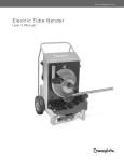
Bench Top Tube Bender User’s Manual ■ Electric and manual units ■ Bends fractional and metric tubing ■ CE compliant Bench Top Bender User’s Manual Contents Safety Instructions . . . . . . . . . . . . . . . . . . . . . . . . . . . . 2 Measuring the Bend Angle . . . . . . . . . . . . . . . . . . . . . . . 16 Technical Data . . . . . . . . . . . . . . . . . . . . . . . . . . . . . . 3 Bend Data Tables Tubing Data . . . . . . . . . . . . . . . . . . . . . . . . . . . . . . . . 3 Fractional Tubing . . . . . . . . . . . . . . . . . . . . . . . . . . . . . 17 Bend Layout . . . . . . . . . . . . . . . . . . . . . . . . . . . . . . . . 4 Metric Tubing . . . . . . . . . . . . . . . . . . . . . . . . . . . . . . . . 22 Fractional Tubing with Metric Dimensions . . . . . . . . 28 Manual Bender Product Information . . . . . . . . . . . . . . . . . . . . . . . . . . 6 Minimum Length of Last Leg Setup . . . . . . . . . . . . . . . . . . . . . . . . . . . . . . . . . . . . . 7 Fractional Tubing . . . . . . . . . . . . . . . . . . . . . . . . . . . . . 33 Calibration . . . . . . . . . . . . . . . . . . . . . . . . . . . . . . . . . . 8 Metric Tubing . . . . . . . . . . . . . . . . . . . . . . . . . . . . . . . . 34 Unloading the Bender . . . . . . . . . . . . . . . . . . . . . . . . . 9 Fractional Tubing with Metric Dimensions . . . . . . . . . 35 Operation . . . . . . . . . . . . . . . . . . . . . . . . . . . . . . . . . . . 10 Maintenance . . . . . . . . . . . . . . . . . . . . . . . . . . . . . . . . . 36 Electric Bender Replacement Parts . . . . . . . . . . . . . . . . . . . . . . . . . . . . 37 Product Information . . . . . . . . . . . . . . . . . . . . . . . . . . 11 Accessories . . . . . . . . . . . . . . . . . . . . . . . . . . . . . . . . . . 38 Setup . . . . . . . . . . . . . . . . . . . . . . . . . . . . . . . . . . . . . . 12 Troubleshooting . . . . . . . . . . . . . . . . . . . . . . . . . . . . . . . 39 Calibration . . . . . . . . . . . . . . . . . . . . . . . . . . . . . . . . . . 14 Warranty . . . . . . . . . . . . . . . . . . . . . . . . . . . . . . . . . . . . . 40 Unloading the Bender . . . . . . . . . . . . . . . . . . . . . . . . . 14 Operation . . . . . . . . . . . . . . . . . . . . . . . . . . . . . . . . . . . 15 Safety Instructions READ THIS MANUAL BEFORE USING THE BENCH TOP TUBE BENDER. WARNING Statements that identify conditions or practices that could result in death or serious injury. CAUTION Statements that identify conditions or practices that could result in minor or moderate injury or damage to property. AUTION - EYE PROTECTION C Eye protection must be worn while operating or working near equipment. AUTION - PINCH POINTS C Keep hands, loose clothing, and long hair away from moving parts. Injury can occur. Bench Top Bender User’s Manual Technical Data Bending Range 1 to 180°. Do not bend tube in excess of 180°. Dimensions (tube bender in case) Width—21 in. (53 cm) Depth—11 in. (28 cm) Height—14.5 in. (37 cm) Weight (tube bender in case, excluding tooling) Manual unit—75 lb (34 kg) Electric unit—79 lb (36 kg) Power Requirements (electric unit) MS-BTB-1—110 V (ac) 50/60 Hz; maximum current: 10 A MS-BTB-2—230 V (ac) 50/60 Hz; maximum current: 5 A Tubing Data ■The Swagelok bench top tube bender bends 1/4, 3/8, 1/2, 5/8, 3/4, 7/8, 1 in., and 1 1/4 in. and 6, 10, 12, 14, 15, 16, 18, 20, 22, 25, 28, and 30 mm outside diameter tubing in a variety of wall thicknesses. ■Tubing should be free of scratches and suitable for bending and flaring. Fractional Tubing Tube OD Approx Bend Radius Carbon Steel Wall Thickness Min/Max Stainless Steel Wall Thickness Min/Max Medium-Pressure Tubing Heavy-Wall Cold Drawn Annealed 1/8 Hard Stainless Steel Stainless Steel Wall Thickness Wall Thickness Min/Max Min/Max Dimensions, in. 1/4 3/8 0.028/0.065 1.42 0.035/0.065 1/2 1/2 2.20 0.035/0.083 0.065/0.095 0.028/0.065 0.083/0.134 0.035/0.083 0.035/0.083 0.083/0.188 0.049/0.109 0.035/0.065 — — 5/8 1.81 — — 3/4 2.20 0.035/0.095 0.049/0.109 0.049/0.095 — — 7/8 2.64 0.049/0.109 — — 1 3.23 0.049/0.120 0.065/0.120 — — 1 1/4 4.41 0.065/0.120 0.083/0.120 — — Carbon Steel Wall Thickness Min/Max Stainless Steel Wall Thickness Min/Max Suggested Tubing Ordering Information High-quality, soft-annealed, seamless carbon steel hydraulic tubing ASTM A179 or equivalent. Hardness 72 HRB (130 HV) or less. Fully annealed, high-quality (Type 304, 316, etc.) (seamless or welded and drawn) stainless steel hydraulic tubing ASTM A269 or A213, or equivalent. Hardness 80 HRB (180 HV) or less. Metric Tubing Tube OD Approx Bend Radius Dimensions, mm 6 36 0.8/1.2 10 36 1.0/1.5 12 36 14 46 15 46 16 46 1.0/2.2 1.0/2.0 1.0/2.2 1.0/2.2 1.0/2.5 1.0/2.2 18 56 1.2/2.5 20 67 1.2/2.8 22 67 25 82 1.2/ 3.0 28 112 1.8/3.0 30 112 1.2/2.8 1.8/3.0 1.8/3.0 2.0/3.0 Suggested Tubing Ordering Information High-quality, soft-annealed, carbon steel hydraulic tubing DIN‑2391 or equivalent. Hardness 130 HV (72 HRB) or less. Fully annealed, high-quality (Type 304, 316, etc.) stainless steel tubing EN ISO 1127 or equivalent. Hardness 180 HV (80 HRB) or less. Bench Top Bender User’s Manual Bend Layout This bender can be used to form single, offset, and other bends. This section contains information for measuring and marking the tube prior to bending. Note: Make all marks 360° around the tube.90 First Single Bend Bend.eps 1.Place a reference mark at the end of the tube from which you are beginning the measurements. 2.Measure from the reference mark and make a measurement mark on the tube at a distance equal to the desired bend length. This mark is the vertex of the bend. 3.Measure the bend deduction distance for the angle being bent from the measurement mark (see Bend Data Tables beginning on page 17) and make a bend mark on the tube. ■ If the bend deduction is positive, place the bend mark toward the reference mark. ■ If the bend deduction is negative, place the bend mark away from the reference mark. 4. Refer to the appropriate Operation section to bend the tube. Desired bend length Measurement mark Second 90 Bend.eps Reference mark Bend deduction Bend mark Single Bend Multiple Bends The Measure-Bend Method 1. Follow Single Bend steps 1 through 4. First desired bend length 12 in. Bend deduction 1 3/4 in. 2.Using the vertex of the previous bend as the reference mark, repeat steps 2 through 4 for the next bend. (The vertex is where the center lines of the two legs of the angle intersect.) Example: Using 5/8 in. OD tube and an aluminum bend shoe, make a 90° bend 12 inches from the reference mark followed by a 45° bend with 12 inches between bends. 1.Place a reference mark at the end of the tube from which you are beginning the measurements. 4.Place the bend mark 1 3/4 in. from the measurement mark going towards the reference mark. 5.Bend tube 90 according to the appropriate Operation section. 6.Measure 12 inches from the vertex of the 90° bend and make a second measurement mark, away from the reference mark. 7.The bend deduction distance in the Fractional Tubing Bend Data table for a 45° bend using 5/8 in. tubing and an aluminum bend shoe is 11/16 in. Vertex 5/8 in. OD tube First Bend (90°) 2.Measure 12 inches from the reference mark and make a measurement mark to indicate the first desired bend length. 3.The bend deduction in the Fractional Tubing Bend Data table for a 90° bend using 5/8 in. tubing and an aluminum bend shoe is 1 3/4 in. Center line Bend mark Reference mark Bend mark Second desired bend length 12 in. Bend deduction 11/16 in. Vertex 45° 8.Place a second bend mark 11/16 in. from the second measurement mark going towards the first bend. 9.Bend tube according to the appropriate Operation section. Second Bend (45°) Bench Top Bender User’s Manual Reverse Bends The Measure-Bend Method Sometimes a multiple bend layout will require that a bend be made in reverse. A reverse bend is made with the end of the tube opposite the reference mark inserted into the bend shoe rather than the end with the reference mark. 1. Measure from the vertex of the preceding bend and place a second measurement mark farther down the tube at a distance equal to the desired length of the leg. 2. Measuring from that measurement mark, place a bend mark on the tube at the bend allowance for the angle being bent. (See Bend Data tables beginning on page 17). ■ If the bend allowance is positive, place the bend mark away from the preceding bend. ■ If the bend allowance is negative, place the bend mark in the direction towards the preceding bend. 3. Bend tube according to the appropriate Operation section. Note: When loading the tube into the bender to make a reverse bend, ensure that the end with the reference mark is not inserted into the bend shoe. Offset Calculations O L E When offset exists, determine the length of offset (L) before calculating for the adjustment from the tube bend. To determine the length of offset, select the offset angle (E). Then, multiply the offset dimension (O) by the offset bend allowance. Angle (E) Offset Bend Allowance Offset (O) Length of Offset (L) 22.5°2.613 3 ________ = _______________ 30°2.000 3 ________ = _______________ 45° 1.414 3 ________ = _______________ 60° 1.154 3 ________ = _______________ Bench Top Bender User’s Manual Manual Bender Product Information Roller bracket assembly Roller pins Bend shoe Roller bracket lever Roller knob Carrying handle High bendspeed selector Bend degree wheel (2 1/2 increments) Medium bendspeed selector Low bendspeed selector Drill yoke support Hand crank Bend shoe Zero reference mark Hex drive shaft D pin Reference mark D roller G pin Clamp arm G roller Support bracket Bracket pin Roller bracket assembly Bracket post Bracket assembly stop Roller bracket lever Bracket post stop Roller knob Aluminum only, recommended when using 1 in. or 25 mm bend shoe. Bench Top Bender User’s Manual CAUTION 5. Install the roller bracket assembly on the bracket post. When lifting the bender, first place one hand under the bender, then pick up the unit by grabbing the carrying handle with your other hand. Note: The roller bracket assembly stop must be to the right of the bracket post stop. Setup 1. Place the hand crank on the high bend-speed selector. 2. Rotate the hand crank until the zero reference mark on the hex drive shaft is between the 2 and 3 o’clock position, when viewed from the operating position. Roller bracket assembly Bracket post Bracket post stop Roller bracket assembly stop 2 o’clock Hex drive shaft 3 o’clock Zero reference mark 6. Place the roller bracket lever on the bracket pin. Note: The lever must be fully bottomed on the pin. 3. Rotate the roller knob counterclockwise until it stops. 7. Lift the roller pins, place the appropriate rollers in the marked locations on the roller bracket, and replace the roller pins. G roller pin D roller pin D roller G roller Roller knob 4. Place the appropriate bend shoe on the hex drive shaft, aligning the zero reference marks on the shoe and the shaft. The bend shoe must be fully bottomed on the hex drive shaft. Bend shoe Roller bracket Roller bracket lever Zero reference marks Note: The roller pins must be fully engaged with the roller bracket assembly. 8. Mark tube according to Bend Layout. 9. Carefully insert the tube into the bend shoe, past the clamp arm. aution C The end of the tube must extend past the right edge of the clamp arm to prevent potential damage to the tube during bending. Hex drive shaft Tube Bend shoe Clamp arm Right edge Bench Top Bender User’s Manual 10. Align the bend mark on the tube with the reference mark on the bend shoe. Bend shoe Reference mark Tube Bend mark To decrease clearance: Rotate the roller knob clockwise while slowly rotating the hand crank counterclockwise. Note: The roller knob must be tight. Note: Do not turn the roller knob after this point or bend consistency will be affected. 11. Turn the roller bracket lever clockwise until the roller bracket assembly stop makes contact with the bracket post stop. Roller bracket lever Roller bracket assembly stop Bracket post stop Hand crank Calibration Contact 12. Hold the tube and turn the roller knob clockwise until the G and D rollers both make contact with the tube and the roller knob is tight. Note: The rollers may need to be guided onto smaller diameter tubing. 13. Ensure there is approximately 3/8 in. or 10 mm clearance between the D roller and the clamp arm of the bend shoe. Clamp arm D roller 3/8 in. To increase clearance: Rotate the roller knob counterclockwise while slowly rotating the hand crank clockwise and maintaining straight tube. Calibration is the process of positioning the bend degree wheel to accurately display the angle being generated by the bender. Calibration accounts for tube variables and mechanical play in the bender, which is typically observed as springback. Different materials, different lots of the same material, and different wall thicknesses of the same material may exhibit different bend characteristics. Once the bender has been calibrated, recalibration is recommended whenever: ■ OD or wall thickness of tube being bent is changed. ■The ■The roller knob has been turned after Calibration completed. bend degree wheel does not accurately display the bend angle. 1. Place the hand crank on the desired speed selector for the tube being bent. ■Low bend-speed selector (1) is suggested for large diameter or heavy-wall tube. ■Medium bend-speed selector (2) is suggested for intermediate size and medium-wall tube. ■High bend-speed selector (3) is suggested for small diameter and thin-wall tube. 2. Slowly rotate the hand crank until the tube begins to deflect or bend (looking to the right of the rollers). ■On low (1) and high (3) bend speeds, rotate the hand crank clockwise. ■On medium (2) bend speed, rotate the hand crank counter-clockwise. Bench Top Bender User’s Manual 3. Keep the hand crank still and rotate the bend degree wheel to zero. aution C Releasing the hand crank while tube is under load may cause the hand crank to spin, possibly leading to injury. 4. Rotate the hand crank until the bend wheel displays 5 less than the desired bend angle. This will prevent setup scrap due to overbending. Example: For a desired bend angle of 90°, rotate the hand crank until the bend degree wheel reads 85°. The bend angle indicated on the bend degree wheel will now be very close to the bend angle produced. If further adjustment is desired repeat steps 6 through 10. Note: Tube springback is cumulative. Depending on the tube variables, a smaller bend angle builds up less tube springback during the bending process than a larger bend angle. For example, if a 30° bend is attempted using a bender that was calibrated to make a 90° bend, the resulting bend may be larger than desired. Conversely, if a 150° bend is attempted on the same bender, the resulting bend may be smaller than desired. It is advised to verify each bend angle. Unloading the Bender Note: Do not turn the roller knob to unload the bender. Doing so will affect bend consistency. Caution 5. Unload the bender (see Unloading the Bender) and measure the bend angle of the tube (see Measuring the Bend Angle). Make note of this measurement as it is likely to be different than the angle displayed on the bend wheel. 6. Reload the tube into the bender, lining up the bend mark and the reference mark. 7. Rotate the hand crank until the bend degree wheel reads the angle from step 4 (in example: 85). Releasing the hand crank while the tube is under load may cause the hand crank to spin, possibly leading to injury. 1. Rotate the hand crank in the direction opposite that used to bend the tube. 2. As the hand crank is rotated, gently push the roller bracket lever counter-clockwise until the rollers swing away from the tube and the tube can be removed from the bender. Note: Do not force the roller bracket lever. Hand crank 8. Keep the hand crank still and rotate the bend degree wheel to the measurement noted in step 5 (in example: 88). This calibrates the bend degree wheel by setting it to display the actual bend angle being produced. 9. Continue to rotate the hand crank until the bend degree wheel reads the desired bend angle. 10. Unload the bender (see Unloading the Bender) and measure the bend angle of the tube. Roller bracket lever 10 Bench Top Bender User’s Manual Operation Before operating the bender mark the tube (see Bend Layout) and follow the Setup and Calibration procedures. Note: If the rollers touch the tube and prevent the stops from making contact, gently turn the roller bracket lever clockwise while rotating the hand crank. CAUTION - PINCH POINTS Hand crank 1. With the zero reference mark between the 2 and 3 o’clock position, place the hand crank on the desired speed selector. ■Low bend-speed selector (1) is suggested for large diameter or heavy-wall tube. ■ Medium ■ Roller bracket lever bend-speed selector (2) is suggested for intermediate size and medium wall tube. High bend-speed selector (3) is suggested for small diameter and thin-wall tube. 2. Insert the tube carefully into the grooved section of the bend shoe, past the clamp arm. CAUTION The end of the tube must extend past the right edge of the clamp arm to prevent potential damage to the tube during bending. 5. Check the following before continuing: ■ he bend mark remains aligned with the reference T mark on the bend shoe. ■ The tube is positioned in the correct plane for bend. ■ The tube will not contact the bender housing during the bend operation (for a multiple bend). Tube Bend shoe Right edge Clamp arm 3. Align the bend mark on the tube with the reference mark on the bend shoe. Undesired tube contact 6. Rotate the hand crank until you reach the desired bend angle on the bend degree wheel. Reference mark ■On low (1) and high (3) bend speeds, rotate the hand crank clockwise to bend the tube. Bend mark ■On medium (2) bend speed, rotate the hand crank counter-clockwise to bend the tube. 7. Unload the tube from the bender. See Unloading the Bender. 4. Turn the roller bracket lever clockwise until the roller bracket assembly stop and the bracket post stop make contact. Roller bracket assembly stop Bracket post stop Contact Note: Do not turn the roller knob or bend consistency will be affected. 8. Verify the bend angle (see Measuring the Bend Angle). Make adjustments if necessary (see Calibration). 9. Use the hand crank on the high bend-speed selector (3) to return the bend shoe to the starting position. Bench Top Bender User’s Manual Electric Bender 11 Rollerbracket assembly Roller pins Product Information Roller bracket lever Bend shoe Carrying handle Roller knob Power cord Foot switch receptacle Toggle switch Bend angle thumb wheels LED display Overload indicator Hex drive shaft Zero reference mark D pin D roller Bend shoe G pin G roller Reference mark Bracket pin Roller bracket Bracket post Bracket assembly stop Bracket post stop Roller bracket lever Roller knob Clamp arm Support bracket Aluminum only, recommended when using 1 in. or 25 mm bend shoe. 12 Bench Top Bender User’s Manual Electric bender must be operated in a safe environment to avoid risk of fire, explosion, or electric shock. 3. Rotate the roller knob counterclockwise until it stops. WARNING Voltage greater than 30 V (ac) is present. WARNING - KEEP DRY. Roller knob Do not expose the equipment to water or wet locations. WARNING - FIRE OR EXPLOSION. Do not use equipment in a combustible or explosive atmosphere. Flammable liquids or gases could ignite. Grounding and Extension Cord Information WARNING Electric bender must be grounded against electrical shock. It is equipped with a three-wire conductor and three-prong plug to fit a grounded receptacle. Never connect the green or green/yellow wire to a live terminal. 4. Place the appropriate bend shoe on the hex drive shaft, aligning the zero reference marks on the shoe and the shaft. The bend shoe must be fully bottomed on the hex drive shaft. Zero reference marks Bend shoe WARNING For safe operation of the electric bender, the extension cord wire size must meet the following specifications: For 0 to 25 ft (0 to 7.5 m), the recommended minimum wire gauge is 14 AWG or 1.5 mm. For 25 to 50 ft (7.5 to 15 m), the recommended minimum wire gauge is 12 AWG or 2.5 mm. CAUTION When lifting the bender, first place one hand under the bender, then pick up the unit by grabbing the carrying handle with your other hand. Setup It is recommended that scrap tube be used during setup and calibration of the Electric Bench Top Tube Bender. Hex drive shaft 5. Install the roller bracket assembly on the bracket post. Note: The roller bracket assembly stop must be to the right of the bracket post stop. Bracket post Bracket post stop Roller bracket assembly stop 1. Plug in the power cord. 2. Hold the toggle switch in the unload direction until the motor stops. The zero reference mark on the hex drive shaft should now be between the 2 and 3 o’clock position. Note: The toggle switch is programmed to have a safety time delay of approximately two seconds between operations. 2 o’clock Hex drive shaft Zero reference mark 3 o’clock 6. Place the roller bracket lever on the bracket pin. Note: The lever must be fully bottomed on the pin. 7. Lift the roller pins, place the G and D rollers in the marked locations on the roller bracket, and replace the roller pins. Note: The roller pins must be fully engaged into the roller bracket assembly. G roller pin D roller pin D roller G roller Roller bracket lever Bracket pin Roller bracket assembly Bench Top Bender User’s Manual 8. Carefully insert the tube into the bend shoe, past the clamp arm. CAUTION The end of the tube must extend past the right edge of the clamp arm to prevent potential damage to the tube during bending. 13 If all three conditions are met, make note of the value appearing on the three right bend angle thumb wheels and proceed to Calibration. If all three conditions are not met: a.Turn the roller knob counter-clockwise until the tube can be removed. Remove tube. b.Advance the right-most bend angle thumb wheel one digit. Bend angle thumb wheel Tube Bend shoe Right edge Clamp arm 9. Turn the roller bracket lever clockwise until the roller bracket assembly stop makes contact with the bracket post stop. c.Hold the toggle switch in the bend direction until the motor stops. Roller bracket assembly stop Bracket post stop Contact 10. Hold the tube in the bend shoe and turn the roller knob clockwise until both the G and D rollers make contact with the tube. Note: Smaller diameter tube may need to be guided into the rollers. d.Repeat steps 9 through 11 until all three conditions are met. 12.Make note of the value on the right-most bend angle thumb wheel. 11. Once the roller knob is tight, the following conditions must be met: Bend angle thumb wheel ■ The roller bracket assembly stop and the bracket post stop must maintain contact. ■ Both rollers must make contact with the tube. ■ There must be approximately 3/8 in. or 10 mm clearance between the D roller and the clamp arm of the bend shoe. Example only 13. Turn the roller knob counter-clockwise until the tube can be removed. Remove tube. Clamp arm 3/8 in. D roller 14. Advance the two right-most bend angle thumb wheels until they display 010 or higher. 15. Hold the toggle switch in the bend direction until the motor stops. Wait two seconds, then hold the toggle switch in the unload direction until the motor stops. 16. Proceed to Calibration. 14 Bench Top Bender User’s Manual Calibration Calibration is the process of accurately accounting for tube variables and mechanical play in the bender, which is typically observed as springback. Different materials, different lots of the same material, and different wall thicknesses of the same material may exhibit different bend characteristics. Once the bender has been calibrated, recalibration is recommended whenever: ■ OD or wall thickness of tube being bent is changed. ■The roller knob has been turned after Calibration has been completed. 1. Set the right-most bend angle thumb wheel to the value noted in step 12 of Setup. Hold the toggle switch in the bend direction until the motor stops (do not jog the switch). 2. Carefully insert the tube into the bend shoe, past the clamp arm. CAUTION The end of the tube must extend past the right edge of the clamp arm to prevent potential damage to the tube during bending. 5. Set the bend angle thumb wheels to the desired bend angle. 6. Hold the toggle switch in the bend direction until the motor stops (do not jog the switch). CAUTION - PINCH POINT 7. Unload the bender (see Unloading the Bender) and measure the bend angle of the tube (see Measuring the Bend Angle). If the actual bend is smaller than the desired bend angle: Subtract the actual bend angle from the desired bend angle. The difference is the amount that must be added to the desired bend angle when setting the bend angle thumb wheels for all subsequent bends made with this tube. For example: The desired bend angle entered is 90°. The resulting calibration sample measures 86°. 90 – 86 = 4. The bend angle thumb wheels must be set 4° more than the desired bend angle for subsequent bends with this size tube, i.e. for a 90° bend, the bend angle thumb wheels must be set at 94°. Bend angle thumb wheels Tube Bend shoe Right edge Clamp arm 3. Turn the roller bracket lever clockwise until the roller bracket assembly stop makes contact with the bracket post stop. Roller bracket assembly stop Bracket post stop Contact 4. Hold the tube in the bend shoe and turn the roller knob clockwise until the G and D rollers both make contact with the tube. Note: The rollers may need to be guided onto smaller diameter tubing. Note: The clearance between the D roller and the clamp arm will now be approximately 1/4 in. Note: Do not turn the roller knob after this point or bend consistency will be affected. If the actual bend is larger than the desired bend angle: Subtract the desired bend angle from the actual bend angle. The difference is the amount that must be subtracted from the desired bend angle for all subsequent bends made with this tube. For example: The desired bend angle entered is 90°. The resulting calibration sample measures 92°. 92 – 90 = 2. The bend angle thumb wheels must be set 2° less than the desired bend angle for subsequent bends with this size tube, i.e. for a 90° bend, the bend angle thumb wheels must be set at 88°. 8. Make note of this amount. Note: Tube springback is cumulative. Depending on the tube variables, a smaller bend angle builds up less tube springback during the bending process than a larger bend angle. For example, if a 30° bend is attempted using a bender that was calibrated to make a 90° bend, the resulting bend may be larger than desired. Conversely, if a 150° bend is attempted on the same bender, the resulting bend may be smaller than desired. It is advised to verify each bend angle. Unloading the Bender Note: Do not turn the roller knob to unload the bender. Doing so will affect bend consistency. 1. Hold the toggle switch in the unload position until the motor stops. While holding the toggle switch, gently turn the roller bracket lever counter-clockwise until the Bench Top Bender User’s Manual 15 5. Align the bend mark on the tube with the reference mark on the bend shoe (see Bend Layout for marking tube). rollers swing away from the tube. Note: Do not force the roller bracket lever. Roller bracket lever Reference mark Bend mark Toggle switch 2. Hold the tube until the motor stops and the tube can be removed from the bender. Operation 6. Rotate the roller bracket lever clockwise until the roller bracket assembly stop and the bracket post stop make contact. Before operating the bender mark the tube (see Bend Layout) and follow the Setup and Calbration procedures. CAUTION - PINCH POINTS Roller bracket assembly stop Bracket post stop 1. Set the bend angle thumb wheels to the value noted in step 12 of Setup. Bend angle thumb wheels Contact Note: The clearance between the D roller and the clamp arm will now be approximately 1/4 in. Example only 7. Check the following before continuing: 2. Hold the toggle switch in the bend direction until the motor stops (do not jog the switch). ■ he bend mark remains aligned with the reference T mark on the bend shoe. 3. Set the bend angle thumb wheels to the desired bend angle plus or minus the amount noted in step 8 of Calibration. ■ The tube is positioned in the correct plane. ■ The tube will not contact the bender housing during the bend operation (for a multiple bend). Bend angle thumb wheels Example only 4. Carefully insert the tube into the bend shoe, past the clamp arm. Caution The end of the tube must extend past the right edge of the tube clamp support area to prevent potential damage to the tube during bending. Tube Undesired tube contact 8. Hold the tube and push the toggle switch in the bend direction until the motor stops (do not jog the switch). 9. Unload the tube. See Unloading the Bender. 10. Verify the bend angle (see Measuring the Bend Angle). Bend shoe Clamp arm Right edge 16 Bench Top Bender User’s Manual Measuring the Bend Angle This is one of many methods that may be used to measure the bend angle. A protractor will be needed for this method. 1. Place the bent tube on a piece of paper with the vertex of the bend on the paper. Tube Vertex 2. Hold the tube against the paper, and mark the paper along one edge of each leg of the bend with a pencil. 3. Align a ruler or other straight edge on one of the marks, and extend it past the point where it will intersect with the second mark when it is extended. 4. Repeat step 3 with the second mark. The intersection point of the two marks represents the vertex of the bend. 5. Place the origin of the protractor on the intersection of the line. Rotate the protractor so the baseline of the protractor is aligned with one of the marks and the second mark intersects the scale on the protractor (extend the marks with a pencil if necessary). Origin 6. The second mark indicates the bend angle. Note: The protractor will contain two scales. Read the appropriate scale. Bench Top Bender User’s Manual Bend Data Tables The bend data provided reflects results achieved using the Swagelok bench top tube bender. Bend deduction – the distance from the vertex of the angle back to the point where the tube breaks tangent and the bend actually begins. Sometimes referred to as ‘setback’, ‘take-up’ or ‘take-off’. Bend length – the actual amount of tube consumed by the bend as measured along the centerline of the bend. Adjustment (gain) – t he difference between the actual length of tube used in a bend and the theoretical distance around a sharp corner. The information provided in these tables accounts for adjustment (gain). Bend allowance – t he bend mark distance for reverse bends. The adjustment (gain) is pushed towards the reference mark or previous bend during reverse bends. Fractional Tubing Dimensions are in inches. 1/4 in. OD, 1.42 in. Bend Radius, 36 mm Bend Shoe Carbon Steel and Stainless Steel Tubing Bend Angle Degrees 15 22 1/2 30 45 60 75 90 105 120 135 150 165 180 Aluminum Bend Shoe Bend Bend Bend Allowance Deduction Length 1/16 1/16 1/8 1/8 3/16 5/16 3/16 1/4 1/2 3/8 7/16 13/16 1/2 11/16 1 3/16 9/16 15/16 1 9/16 5/8 1 5/16 1 15/16 9/16 1 11/16 2 1/4 3/8 2 5/16 2 5/8 –1/4 3 1/4 3 –1 3/4 5 1/16 3 3/8 –6 13/16 10 9/16 3 3/4 2 13/16 1 5/16 4 1/16 Bend Allowance 5/16 3/8 7/16 5/8 3/4 13/16 7/8 13/16 1/2 –1/8 –1 5/8 –6 13/16 3 1/16 Medium–Pressure Tubing Steel Bend Shoe Bend Bend Deduction Length 5/16 5/8 7/16 13/16 1/2 1 11/16 1 5/16 15/16 1 11/16 1 3/16 2 1/16 1 9/16 2 7/16 2 2 3/4 2 5/8 3 1/8 3 5/8 3 1/2 5 1/2 3 7/8 11 4 1/4 1 9/16 4 9/16 Bend Allowance 3/8 7/16 9/16 11/16 13/16 15/16 15/16 7/8 5/8 –1/16 –1 9/16 –6 3/4 3 3/16 Steel Bend Shoe Bend Deduction 3/8 1/2 9/16 3/4 1 1 1/4 1 5/8 2 1/16 2 11/16 3 11/16 5 5/8 11 1/8 1 5/8 Bend Length 3/4 15/16 1 1/8 1 1/2 1 13/16 2 3/16 2 9/16 2 15/16 3 5/16 3 11/16 4 1/16 4 7/16 4 3/4 3/8 in. OD, 1.42 in. Bend Radius, 36 mm Bend Shoe Carbon Steel and Stainless Steel Tubing Bend Angle Degrees 15 22 1/2 30 45 60 75 90 105 120 135 150 165 180 Aluminum Bend Shoe Bend Bend Bend Allowance Deduction Length –1/16 –1/16 –1/16 0 1/16 1/8 1/8 1/8 5/16 1/4 5/16 11/16 7/16 9/16 1 1/2 13/16 1 3/8 9/16 1 3/16 1 3/4 9/16 1 9/16 2 1/8 3/8 2 1/8 2 1/2 –3/16 3 1/16 2 7/8 –1 11/16 4 7/8 3 1/4 –6 3/4 10 5/16 3 5/8 2 13/16 1 3/16 3 15/16 Steel Bend Shoe Bend Bend Allowance Deduction 1/16 1/16 1/8 3/16 1/4 1/4 3/8 7/16 1/2 11/16 5/8 15/16 5/8 1 5/16 5/8 1 11/16 3/8 2 5/16 –3/16 3 1/4 –1 11/16 5 1/16 –6 3/4 10 9/16 2 7/8 1 5/16 Medium-Pressure Tubing Bend Length 1/8 5/16 1/2 7/8 1 3/16 1 9/16 1 15/16 2 5/16 2 11/16 3 1/16 3 7/16 3 13/16 4 1/8 Bend Allowance 5/16 3/8 7/16 5/8 3/4 13/16 13/16 3/4 1/2 –3/16 –1 11/16 –6 7/8 3 Steel Bend Shoe Bend Bend Deduction Length 5/16 5/8 7/16 13/16 1/2 15/16 11/16 1 5/16 15/16 1 11/16 1 3/16 2 1 9/16 2 3/8 2 2 3/4 2 5/8 3 1/8 3 5/8 3 7/16 5 1/2 3 13/16 11 4 3/16 1 9/16 4 1/2 17 18 Bench Top Bender User’s Manual Fractional Tubing continued Dimensions are in inches. 1/2 in. OD, 1.42 in. Bend Radius, 36 mm Bend Shoe Carbon Steel and Stainless Steel Tubing Bend Angle Degrees 15 22 1/2 30 45 60 75 90 105 120 135 150 165 180 Aluminum Bend Shoe Bend Bend Bend Allowance Deduction Length –1/16 –1/16 –1/8 0 1/16 1/16 1/16 1/8 3/16 1/4 5/16 9/16 3/8 9/16 15/16 7/16 13/16 1 1/4 7/16 1 3/16 1 5/8 7/16 1 9/16 2 1/4 2 1/8 2 3/8 –3/8 3 1/16 2 11/16 –1 13/16 4 7/8 3 1/16 –6 15/16 2 5/8 10 5/16 1 3/16 3 7/16 3 3/4 –6 7/8 2 13/16 1/2 in. OD, 2.20 in. Bend Radius, 56 mm Bend Shoe Carbon Steel and Stainless Steel Tubing Bend Angle Degrees 15 22 1/2 30 45 60 75 90 105 120 135 150 165 180 Bend Allowance 5/8 3/4 7/8 1 1/8 1 5/16 1 7/16 1 1/2 1 5/16 7/8 –1/8 –2 1/2 –10 1/2 4 7/8 Steel Bend Shoe Bend Bend Deduction Length 5/8 1 1/4 13/16 1 1/2 15/16 1 13/16 1 1/4 2 3/8 1 5/8 2 15/16 2 1/16 3 1/2 2 9/16 4 1/16 3 1/4 4 5/8 4 1/4 5 3/16 5 13/16 5 3/4 8 13/16 6 5/16 17 5/16 6 7/8 2 9/16 7 7/16 Medium-Pressure Tubing Steel Bend Shoe Bend Bend Bend Allowance Deduction Length 1/8 1/8 1/4 3/16 1/4 7/16 1/4 5/16 9/16 7/16 1/2 15/16 9/16 3/4 1 5/16 5/8 1 1 5/8 5/8 1 3/8 2 9/16 1 3/4 2 3/8 3/8 2 3/8 2 3/4 –1/4 3 5/16 3 1/16 –1 3/4 5 3/16 3 7/16 10 11/16 1 3/8 3 13/16 4 1/8 Bend Allowance 1/16 3/16 1/4 3/8 9/16 5/8 5/8 5/8 3/8 –1/4 –1 11/16 –6 13/16 2 13/16 Steel Bend Shoe Bend Bend Deduction Length 1/16 3/16 3/16 3/8 5/16 9/16 1/2 7/8 3/4 1 1/4 1 1 5/8 1 5/16 2 1 3/4 2 5/16 2 5/16 2 11/16 3 5/16 3 1/16 5 1/8 3 7/16 10 5/8 1 5/16 3 13/16 4 1/8 Bench Top Bender User’s Manual Fractional Tubing continued Dimensions are in inches. 5/8 in. OD, 1.81 in. Bend Radius, 46 mm Bend Shoe Carbon Steel and Stainless Steel Tubing Bend Angle Degrees 15 22 1/2 30 45 60 75 90 105 120 135 150 165 180 Aluminum Bend Shoe Bend Bend Bend Allowance Deduction Length 3/16 3/16 3/8 5/16 5/16 5/8 3/8 7/16 7/8 9/16 11/16 1 5/16 3/4 1 1 3/4 7/8 1 3/8 2 1/4 15/16 1 3/4 2 11/16 13/16 2 5/16 3 1/8 1/2 3 1/16 3 5/8 –1/4 4 5/16 4 1/16 –2 3/16 6 11/16 4 1/2 –8 11/16 3 11/16 13 11/16 1 3/4 5 5 7/16 Bend Allowance 3/8 1/2 9/16 3/4 15/16 1 1/16 1 1/16 15/16 9/16 –3/16 –2 3/16 Steel Bend Shoe Bend Deduction 3/8 1/2 5/8 7/8 1 3/16 1 9/16 1 15/16 2 9/16 3 5/16 4 5/8 7 Bend Length 3/4 1 1 3/16 1 11/16 2 1/8 2 9/16 3 3 1/2 3 15/16 4 3/8 4 13/16 –8 3/4 3 13/16 14 1/16 1 15/16 5 5/16 5 3/4 3/4 in. OD, 2.20 in. Bend Radius, 56 mm Bend Shoe Carbon Steel and Stainless Steel Tubing Bend Angle Degrees 15 22 1/2 30 45 60 75 90 105 120 135 150 165 180 Aluminum Bend Shoe Bend Bend Bend Allowance Deduction Length 3/8 3/8 3/4 1/2 9/16 1 5/8 11/16 1 5/16 7/8 1 1 7/8 1 1/16 1 3/8 2 7/16 1 3/16 1 13/16 2 15/16 1 1/4 2 5/16 3 1/2 1 1/8 3 4 1/16 11/16 3 15/16 4 5/8 –1/4 5 7/16 5 3/16 –2 5/8 8 3/8 5 3/4 –10 9/16 16 7/8 6 5/16 4 9/16 2 5/16 6 7/8 Bend Allowance 1/2 5/8 3/4 1 1 1/4 1 3/8 1 7/16 1 1/4 13/16 –1/8 –2 1/2 –10 1/2 4 3/4 Steel Bend Shoe Bend Bend Deduction Length 9/16 1 1/16 11/16 1 5/16 13/16 1 5/8 1 3/16 2 3/16 1 1/2 2 3/4 1 15/16 3 5/16 2 7/16 3 7/8 3 3/16 4 7/16 4 1/8 5 5 11/16 5 9/16 8 5/8 6 1/8 17 3/16 6 11/16 2 7/16 7 1/4 19 20 Bench Top Bender User’s Manual Fractional Tubing continued Dimensions are in inches. 7/8 in. OD, 2.64 in. Bend Radius, 67 mm Bend Shoe Carbon Steel and Stainless Steel Tubing Bend Angle Degrees 15 22 1/2 30 45 60 75 90 105 120 135 150 165 180 Aluminum Bend Shoe Bend Bend Bend Allowance Deduction Length 1/4 1/4 1/2 3/8 7/16 13/16 9/16 5/8 1 3/16 7/8 1 1 7/8 1 1/8 1 7/16 2 9/16 1 5/16 1 15/16 3 3/16 1 3/8 2 9/16 3 7/8 1 1/4 3 5/16 4 9/16 13/16 4 7/16 5 1/4 –5/16 6 1/4 5 15/16 –3 1/16 9 11/16 6 5/8 –12 9/16 5 7/16 19 7/8 2 9/16 7 5/16 8 Bend Allowance 0 1/8 5/16 9/16 13/16 1 1 1/16 1 5/8 –7/16 –3 3/16 –12 11/16 5 1/8 Steel Bend Shoe Bend Bend Deduction Length 0 0 3/16 5/16 3/8 11/16 3/4 1 5/16 1 3/16 2 1 11/16 2 11/16 2 5/16 3 3/8 3 1/16 4 1/16 4 1/8 4 11/16 5 7/8 5 3/8 9 1/4 6 1/16 19 7/16 2 5/16 6 3/4 7 7/16 1 in. OD, 3.23 in. Bend Radius, 82 mm Bend Shoe Carbon Steel and Stainless Steel Tubing Bend Angle Degrees 15 22 1/2 30 45 60 75 90 105 120 135 150 165 180 Aluminum Bend Shoe Bend Bend Bend Allowance Deduction Length 15/16 15/16 1 13/16 1 1/8 1 1/8 2 1/4 1 5/16 1 3/8 2 11/16 1 11/16 1 13/16 3 1/2 2 2 3/8 4 3/8 2 1/4 3 5 1/4 2 5/16 3 3/4 6 1/16 2 1/8 4 13/16 6 15/16 1 1/2 6 1/4 7 3/4 1/16 8 9/16 8 5/8 –3 7/16 12 7/8 9 7/16 –15 1/8 25 7/16 10 5/16 7 7/16 3 3/4 11 1/8 Bend Allowance 1/2 11/16 7/8 1 1/4 1 9/16 1 3/4 1 13/16 1 11/16 1 1/8 –1/4 –3 11/16 –15 5/16 6 7/8 Steel Bend Shoe Bend Bend Deduction Length 1/2 15/16 11/16 1 3/8 15/16 1 13/16 1 3/8 2 5/8 1 15/16 3 7/16 2 9/16 4 5/16 3 5/16 5 1/8 4 5/16 6 5 11/16 6 13/16 7 7/8 7 5/8 12 3/16 8 1/2 24 5/8 9 5/16 3 5/16 10 1/8 Bench Top Bender User’s Manual Fractional Tubing continued Dimensions are in inches. 1 1/4 in. OD, 4.41 in. Bend Radius, 112 mm Bend Shoe Standard Tubing Bend Angle Degrees 15 22 1/2 30 45 60 75 90 105 120 135 150 165 180 Carbon Steel and Stainless Steel Tubing Bend Bend Bend Allowance Deduction Length 13/16 7/8 1 11/16 1 1/16 1 3/16 2 3/16 1 5/16 1 7/16 2 3/4 1 3/4 2 1/8 3 7/8 2 1/8 2 13/16 5 2 7/16 3 11/16 6 1/16 2 1/2 4 11/16 7 3/16 2 3/16 6 1/16 8 1/4 1 3/8 8 9 3/8 –9/16 11 1/16 10 1/2 –5 5/16 16 15/16 11 9/16 –21 5/16 9 1/8 34 4 11/16 12 11/16 13 13/16 21 22 Bench Top Bender User’s Manual Metric Tubing Dimensions are in millimeters. 6 mm OD, 36 mm Bend Radius, 36 mm Bend Shoe Carbon Steel and Stainless Steel Tubing Bend Angle Degrees 15 22 1/2 30 45 60 75 90 105 120 135 150 165 180 Aluminum Bend Shoe Bend Bend Bend Allowance Deduction Length –1 0 –1 1 2 4 4 5 8 7 10 17 11 16 26 13 23 35 14 31 45 13 41 54 7 56 63 –8 79 72 –45 126 81 –174 68 264 31 Bend Allowance 8 10 13 16 20 22 23 20 13 –3 –42 90 99 –173 77 Steel Bend Shoe Bend Bend Deduction Length 9 17 11 22 14 26 19 35 25 44 32 53 40 63 52 72 68 81 93 90 141 99 281 40 108 117 10 mm OD, 36 mm Bend Radius, 36 mm Bend Shoe Carbon Steel and Stainless Steel Tubing Bend Angle Degrees 15 22 1/2 30 45 60 75 90 105 120 135 150 165 180 Aluminum Bend Shoe Bend Bend Bend Allowance Deduction Length –1 0 –1 1 2 4 4 5 8 7 10 17 11 16 26 13 23 35 14 31 45 13 41 54 7 56 63 –8 79 72 –45 126 81 –174 264 90 68 31 99 Bend Allowance 4 6 8 11 14 16 17 14 8 –8 –47 –177 69 Steel Bend Shoe Bend Bend Deduction Length 5 9 7 13 10 18 15 26 21 35 28 44 36 53 47 61 62 70 87 79 134 88 273 96 36 105 Bench Top Bender User’s Manual Metric Tubing continued Dimensions are in millimeters. 12 mm OD, 36 mm Bend Radius, 36 mm Bend Shoe Carbon Steel and Stainless Steel Tubing Bend Angle Degrees 15 22 1/2 30 45 60 75 90 105 120 135 150 165 180 Aluminum Bend Shoe Bend Bend Bend Allowance Deduction Length -3 -2 -5 -1 0 0 2 3 4 5 8 13 9 14 22 11 21 31 12 29 41 11 39 50 6 53 59 -9 76 68 -46 123 77 -175 66 261 29 Bend Allowance 1 3 5 9 12 14 15 14 8 -7 -45 86 95 -175 69 Steel Bend Shoe Bend Bend Deduction Length 2 3 4 8 7 12 12 21 18 30 25 39 33 48 43 57 58 66 82 75 129 84 268 33 93 102 14 mm OD, 46 mm Bend Radius, 46 mm Bend Shoe Carbon Steel and Stainless Steel Tubing Bend Angle Degrees 15 22 1/2 30 45 60 75 90 105 120 135 150 165 180 Aluminum Bend Shoe Bend Bend Bend Allowance Deduction Length 5 6 11 8 9 17 11 12 23 16 19 35 20 26 47 24 35 58 25 46 70 23 59 82 15 79 94 –4 110 106 –53 171 118 –219 348 130 96 46 142 Bend Allowance 8 11 13 18 22 25 25 22 13 –7 –57 –224 94 Steel Bend Shoe Bend Bend Deduction Length 9 17 12 23 15 29 22 40 30 52 38 63 49 74 63 86 84 97 116 108 177 120 355 131 49 143 23 24 Bench Top Bender User’s Manual Metric Tubing continued Dimensions are in millimeters. 15 mm OD, 46 mm Bend Radius, 46 mm Bend Shoe Carbon Steel and Stainless Steel Tubing Bend Angle Degrees 15 22 1/2 30 45 60 75 90 105 120 135 150 165 180 Aluminum Bend Shoe Bend Bend Bend Allowance Deduction Length 4 5 9 7 8 15 10 11 21 15 18 32 19 25 44 22 34 56 23 45 68 21 58 80 14 78 91 –6 109 103 –54 169 115 –220 94 347 45 Bend Allowance 8 11 14 19 23 27 28 25 17 –3 –52 127 139 –218 99 Steel Bend Shoe Bend Bend Deduction Length 9 17 12 23 15 29 22 41 29 53 38 64 49 76 63 88 83 100 115 112 176 124 354 49 136 148 16 mm OD, 46 mm Bend Radius, 46 mm Bend Shoe Carbon Steel and Stainless Steel Tubing Bend Angle Degrees 15 22 1/2 30 45 60 75 90 105 120 135 150 165 180 Aluminum Bend Shoe Bend Bend Bend Allowance Deduction Length 5 6 11 8 9 16 10 12 22 15 19 34 19 26 46 22 35 57 23 46 69 21 59 80 13 79 92 –7 110 104 –56 171 115 –222 348 127 93 46 139 Bend Allowance 6 8 11 16 20 23 24 22 14 –6 –55 –221 95 Steel Bend Shoe Bend Bend Deduction Length 6 12 9 18 12 23 19 35 27 47 35 59 46 70 60 82 80 94 111 105 172 117 349 129 46 141 Bench Top Bender User’s Manual Metric Tubing continued Dimensions are in millimeters. 18 mm OD, 56 mm Bend Radius, 56 mm Bend Shoe Carbon Steel and Stainless Steel Tubing Bend Angle Degrees 15 22 1/2 30 45 60 75 90 105 120 135 150 165 180 Aluminum Bend Shoe Bend Bend Bend Allowance Deduction Length 8 8 16 11 12 23 14 16 30 20 24 44 25 33 58 28 44 72 29 57 86 26 74 101 16 98 115 –8 137 129 –68 211 143 –270 114 427 57 Bend Allowance 14 17 20 27 32 35 36 33 22 –3 –64 157 171 –268 122 Steel Bend Shoe Bend Bend Deduction Length 14 28 18 35 22 42 30 57 39 71 50 85 63 99 81 114 106 128 146 142 221 156 438 63 171 185 20 mm OD, 67 mm Bend Radius, 67 mm Bend Shoe Carbon Steel and Stainless Steel Tubing Bend Angle Degrees 15 22 1/2 30 45 60 75 90 105 120 135 150 165 180 Aluminum Bend Shoe Bend Bend Bend Allowance Deduction Length 3 4 7 7 8 15 11 13 24 18 23 41 24 34 57 28 46 74 29 62 91 27 81 108 16 109 125 –12 154 142 –83 242 159 –324 500 176 130 62 192 Bend Allowance 1 5 9 17 23 28 29 27 17 –10 –80 –321 132 Steel Bend Shoe Bend Bend Deduction Length 2 3 6 12 11 20 21 38 32 55 44 72 60 89 79 106 107 124 151 141 238 158 496 175 60 192 25 26 Bench Top Bender User’s Manual Metric Tubing continued Dimensions are in millimeters. 22 mm OD, 67 mm Bend Radius, 67 mm Bend Shoe Carbon Steel and Stainless Steel Tubing Bend Angle Degrees 15 22 1/2 30 45 60 75 90 105 120 135 150 165 180 Aluminum Bend Shoe Bend Bend Bend Allowance Deduction Length 9 10 19 13 14 27 17 19 36 24 29 53 30 40 69 34 52 86 35 68 103 32 88 120 20 117 137 –9 163 154 –81 252 171 –323 136 511 68 Bend Allowance 7 11 15 22 29 33 35 32 21 –8 –78 188 204 –320 138 Steel Bend Shoe Bend Bend Deduction Length 7 14 12 23 16 31 26 49 37 66 50 83 66 100 86 117 114 135 160 152 248 169 506 66 186 203 25 mm OD, 82 mm Bend Radius, 82 mm Bend Shoe Carbon Steel and Stainless Steel Tubing Bend Angle Degrees 15 22 1/2 30 45 60 75 90 105 120 135 150 165 180 Aluminum Bend Shoe Bend Bend Bend Allowance Deduction Length 24 25 49 29 30 60 34 36 70 43 48 91 51 61 113 57 77 134 59 96 155 53 123 176 36 161 197 –1 219 218 –90 329 239 –388 649 260 186 96 282 Bend Allowance 12 16 21 29 37 41 43 38 23 –13 –101 –397 166 Steel Bend Shoe Bend Bend Deduction Length 13 24 18 35 24 45 36 65 49 86 65 106 84 127 109 147 145 168 201 188 309 209 627 229 84 250 Bench Top Bender User’s Manual Metric Tubing continued Dimensions are in millimeters. 28 mm OD, 112 mm Bend Radius, 112 mm Bend Shoe Carbon Steel and Stainless Steel Tubing Bend Angle 15 22 1/2 30 45 60 75 90 105 120 135 150 Bend Allowance 11 18 24 36 46 53 55 50 30 –17 –136 165 180 –541 224 Degrees Steel Bend Shoe Bend Bend Deduction Length 12 23 20 37 28 51 44 80 62 108 83 136 110 164 143 193 191 221 267 249 414 277 846 110 306 334 30 mm OD, 112 mm Bend Radius, 112 mm Bend Shoe Carbon Steel and Stainless Steel Tubing Bend Angle Degrees 15 22 1/2 30 45 60 75 90 105 120 135 150 165 180 Bend Allowance 9 15 22 34 44 51 53 48 29 –18 –136 –540 223 Steel Bend Shoe Bend Bend Deduction Length 10 18 17 32 25 47 41 75 60 103 81 132 107 160 140 188 187 217 263 245 410 273 842 302 107 330 27 28 Bench Top Bender User’s Manual Fractional Tubing with Metric Dimensions Tube OD is in inches. Bend radius, bend shoe, and bend dimensions are in millimeters. 1/4 in. OD, 36 mm Bend Radius, 36 mm Bend Shoe Carbon Steel and Stainless Steel Tubing Bend Angle Degrees 15 22 1/2 30 45 60 75 90 105 120 135 150 165 180 Aluminum Bend Shoe Bend Bend Bend Allowance Deduction Length 1 2 3 3 4 7 5 6 12 9 12 21 13 18 30 15 25 40 16 33 49 15 43 58 9 58 67 –6 82 76 –44 129 85 –174 71 268 33 Medium-Pressure Tubing Steel Bend Shoe Bend Bend Bend Allowance Deduction Length 8 8 16 10 10 20 12 13 25 16 18 34 19 24 43 21 31 52 22 39 62 20 51 71 13 67 80 –3 92 89 –42 140 98 95 104 –173 77 280 39 107 117 Bend Allowance 9 12 14 18 21 24 25 22 15 –1 –40 –171 81 Steel Bend Shoe Bend Bend Deduction Length 10 19 12 24 14 28 20 38 26 47 33 56 41 66 53 75 69 84 94 93 143 103 283 41 112 121 3/8 in. OD, 36 mm Bend Radius, 36 mm Bend Shoe Carbon Steel and Stainless Steel Tubing Bend Angle Degrees 15 22 1/2 30 45 60 75 90 105 120 135 150 165 180 Aluminum Bend Shoe Bend Bend Bend Allowance Deduction Length –1 –1 –2 1 2 3 3 4 7 7 9 17 11 15 26 13 22 35 14 31 45 14 41 54 8 55 63 –6 79 73 –43 125 82 –173 264 91 70 31 101 Steel Bend Shoe Bend Bend Bend Allowance Deduction Length 1 2 3 4 4 8 6 6 12 10 12 22 13 18 31 16 25 40 17 33 50 16 43 59 10 58 68 –5 82 77 –43 129 87 –172 268 96 73 33 105 Medium-Pressure Tubing Bend Allowance 7 10 12 15 19 21 21 19 12 –4 –43 –174 76 Steel Bend Shoe Bend Bend Deduction Length 8 15 10 20 13 25 18 34 24 43 31 52 39 61 51 70 67 79 92 88 140 97 280 106 39 115 Bench Top Bender User’s Manual Fractional Tubing with Metric Dimensions continued Tube OD is in inches. Bend radius, bend shoe, and bend dimensions are in millimeters. 1/2 in. OD, 36 mm Bend Radius, 36 mm Bend Shoe Carbon Steel and Stainless Steel Tubing Bend Angle Degrees 15 22 1/2 30 45 60 75 90 105 120 135 150 165 180 Aluminum Bend Shoe Bend Bend Bend Allowance Deduction Length –2 –2 –4 0 1 1 2 3 5 6 9 14 9 14 23 11 21 32 12 30 42 11 40 51 6 54 60 –9 78 69 –46 124 78 –176 66 262 30 87 96 1/2 in. OD, 56 mm Bend Radius, 56 mm Bend Shoe Carbon Steel and Stainless Steel Tubing Bend Angle Degrees 15 22 1/2 30 45 60 75 90 105 120 135 150 165 180 Bend Allowance 16 19 22 28 33 37 38 34 23 –2 –63 –267 124 Steel Bend Shoe Bend Bend Deduction Length 16 32 20 39 24 46 32 60 41 74 52 89 65 103 83 117 109 131 148 146 223 160 441 174 65 189 Medium-Pressure Tubing Steel Bend Shoe Bend Bend Bend Allowance Deduction Length 3 3 6 5 6 10 7 8 15 11 13 24 14 19 33 16 26 42 17 35 51 15 45 60 9 60 69 –6 85 78 –45 132 87 –175 71 271 35 96 105 Bend Allowance 2 4 6 10 13 16 17 15 9 –6 –44 –174 72 Steel Bend Shoe Bend Bend Deduction Length 2 4 5 9 7 14 13 23 18 32 25 41 34 50 44 59 59 69 84 78 131 87 270 34 96 105 29 30 Bench Top Bender User’s Manual Fractional Tubing with Metric Dimensions continued Tube OD is in inches. Bend radius, bend shoe, and bend dimensions are in millimeters. 5/8 in. OD, 46 mm Bend Radius, 46 mm Bend Shoe Carbon Steel and Stainless Steel Tubing Bend Angle Degrees 15 22 1/2 30 45 60 75 90 105 120 135 150 165 180 Aluminum Bend Shoe Bend Bend Bend Allowance Deduction Length 6 6 10 8 8 16 10 12 22 15 18 33 19 26 45 22 34 57 23 45 68 21 59 80 13 79 92 –7 110 103 –56 170 115 –221 93 348 45 Bend Allowance 9 12 15 19 23 26 27 24 15 –5 –55 126 138 –222 96 Steel Bend Shoe Bend Bend Deduction Length 10 20 13 25 16 31 23 43 31 54 39 66 50 77 65 89 85 100 117 112 178 123 357 50 135 146 3/4 in. OD, 56 mm Bend Radius, 56 mm Bend Shoe Carbon Steel and Stainless Steel Tubing Bend Angle Degrees 15 22 1/2 30 45 60 75 90 105 120 135 150 165 180 Aluminum Bend Shoe Bend Bend Bend Allowance Deduction Length 9 10 19 12 14 26 16 17 33 22 26 47 27 35 61 30 45 75 31 58 89 28 76 104 18 100 118 –7 139 132 –67 213 146 –269 429 160 116 58 174 Bend Allowance 13 17 20 26 31 35 36 32 21 –4 –64 –267 121 Steel Bend Shoe Bend Bend Deduction Length 14 27 18 34 21 41 30 56 39 70 49 84 62 98 80 112 105 127 145 141 219 155 436 169 62 184 Bench Top Bender User’s Manual Fractional Tubing with Metric Dimensions continued Tube OD is in inches. Bend radius, bend shoe, and bend dimensions are in millimeters. 7/8 in. OD, 67 mm Bend Radius, 67 mm Bend Shoe Carbon Steel and Stainless Steel Tubing Bend Angle Degrees 15 22 1/2 30 45 60 75 90 105 120 135 150 165 180 Aluminum Bend Shoe Bend Bend Bend Allowance Deduction Length 6 6 12 10 11 21 14 16 30 22 25 47 28 36 64 33 49 82 34 65 99 32 85 116 21 113 134 –7 158 151 –78 246 168 –320 138 505 65 186 203 Bend Allowance 0 4 8 15 21 26 27 25 15 –12 –82 –322 130 Steel Bend Shoe Bend Bend Deduction Length 0 0 5 8 9 17 19 34 30 51 43 68 58 86 77 103 105 120 149 137 236 154 494 58 171 189 1 in. OD, 82 mm Bend Radius, 82 mm Bend Shoe Carbon Steel and Stainless Steel Tubing Bend Angle Degrees 15 22 1/2 30 45 60 75 90 105 120 135 150 165 180 Aluminum Bend Shoe Bend Bend Bend Allowance Deduction Length 23 23 47 28 29 57 34 35 68 43 47 90 51 60 111 57 76 133 59 95 154 54 122 175 38 159 197 2 217 218 –87 327 240 –385 646 261 188 95 283 Bend Allowance 12 17 22 31 39 45 47 43 29 –6 –93 –389 174 Steel Bend Shoe Bend Bend Deduction Length 12 24 18 35 24 46 36 67 49 88 65 109 84 130 109 152 144 173 200 194 309 215 626 236 84 258 31 32 Bench Top Bender User’s Manual Fractional Tubing with Metric Dimensions continued Tube OD is in inches. Bend radius, bend shoe, and bend dimensions are in millimeters. 1 1/4 in. OD, 112 mm Bend Radius, 112 mm Bend Shoe Carbon Steel and Stainless Steel Tubing Bend Angle 15 22 1/2 30 45 60 75 90 105 120 135 150 Bend Allowance 20 27 33 45 54 61 63 56 35 –15 –136 165 180 –154 231 Degrees Steel Bend Shoe Bend Bend Deduction Length 22 42 29 56 37 70 53 98 72 126 93 154 119 182 154 210 203 238 281 266 430 294 864 119 322 350 Bench Top Bender User’s Manual 33 Minimum Length of Last Leg During bending, both rollers must remain on the tube until the desired bend angle is achieved. If the length of tube is too short, the bend may not reach its desired angle or the end of the tube may be damaged. Specifying a final leg length equal to or greater than the minimum length of last leg length in the following tables will ensure a sufficient amount of tube exists to allow the final bend to be made correctly. Minimum Length of Last Leg Tables Fractional Tubing Dimensions are in inches. Aluminum Bend Shoe 1/4 3/8 1/2 5/8 3/4 7/8 1 1.42 2 9/16 1.42 2 1/2 1.42 2 11/16 1.81 3 1/2 2.20 4 1/4 2.64 3 11/16 3.23 4 11/16 2 11/16 2 3/4 2 15/16 2 5/8 2 3/4 2 15/16 2 13/16 2 7/8 3 3/16 3 7/16 3 13/16 4 3/16 4 13/16 5 3/4 7 9/16 13 1/16 3 13/16 3 3/16 3 7/16 3 3/4 4 3/16 4 3/4 5 11/16 7 1/2 12 15/16 3 3/4 3 1/16 3 5/16 3 9/16 3 15/16 4 5/16 4 7/8 5 13/16 7 5/8 13 1/16 3 15/16 3 5/8 3 3/4 4 4 5/16 4 11/16 5 1/16 5 5/8 6 3/8 7 5/8 10 17 5 1/16 4 7/16 4 9/16 4 7/8 5 1/4 5 11/16 6 3/16 6 7/8 7 13/16 9 5/16 12 1/4 20 3/4 6 3/16 3 7/8 4 1/16 4 7/16 4 7/8 5 3/8 6 6 3/4 7 7/8 9 11/16 13 1/8 23 5/16 6 4 7/8 5 1/8 5 9/16 6 1/8 6 3/4 7 1/2 8 9/16 10 12 5/16 16 5/8 29 3/16 7 1/2 3/8 3/8 Medium Pressure 1/2 1/2 Medium Pressure 1/2 5/8 1.42 3 5/8 3 3/4 3 13/16 4 4 1/4 4 1/2 4 7/8 5 1/4 5 7/8 6 13/16 8 5/8 14 1/8 4 7/8 1.42 3 1/2 3 5/8 3 11/16 3 7/8 4 1/8 4 3/8 4 3/4 5 3/16 5 13/16 6 13/16 8 11/16 14 3/16 4 3/4 1.42 3 3/8 3 1/2 3 9/16 3 3/4 4 4 1/4 4 5/8 5 5 5/8 6 9/16 8 7/16 13 15/16 4 5/8 1.42 3 5/16 3 7/16 3 9/16 3 3/4 4 4 1/4 4 9/16 5 5 9/16 6 9/16 8 3/8 13 7/8 4 9/16 2.20 4 1/4 4 7/16 4 9/16 4 7/8 5 1/4 5 11/16 6 3/16 6 7/8 7 7/8 9 7/16 12 7/16 20 15/16 6 3/16 1.81 3 11/16 3 13/16 3 15/16 4 3/16 4 1/2 4 7/8 5 1/4 5 7/8 6 5/8 7 15/16 10 5/16 17 3/8 5 1/4 Bend Angle, Degrees Tube OD Bend Radius 15 22 1/2 30 45 60 75 90 105 120 135 150 165 180 Steel Bend Shoe 1/4 Bend Radius 15 22 1/2 30 45 60 75 90 105 120 135 150 165 180 1.42 3 7/16 3 9/16 3 5/8 3 13/16 4 1/16 4 5/16 4 11/16 5 1/8 5 3/4 6 3/4 8 5/8 14 1/8 4 11/16 1.42 3 1/2 3 5/8 3 11/16 3 7/8 4 1/8 4 3/8 4 3/4 5 3/16 5 13/16 6 13/16 8 3/4 14 1/4 4 3/4 Bend Angle, Degrees Tube OD 1/4 Medium Pressure 3/4 7/8 1 1 1/4 2.20 2.64 3.23 4.41 4 5/16 4 7/16 5 1/4 5 3/4 4 7/16 4 5/8 5 7/16 6 1/16 4 9/16 4 13/16 5 11/16 6 5/16 4 15/16 5 3/16 6 1/8 7 5 1/4 5 5/8 6 11/16 7 11/16 5 11/16 6 1/8 7 5/16 8 9/16 6 3/16 6 3/4 8 1/16 9 9/16 6 15/16 7 1/2 9 1/16 10 15/16 7 7/8 8 9/16 10 7/16 12 7/8 9 7/16 10 5/16 12 5/8 15 15/16 12 3/8 13 11/16 16 15/16 21 13/16 20 15/16 23 7/8 29 3/8 38 7/8 6 3/16 6 3/4 8 1/16 9 9/16 34 Bench Top Bender User’s Manual Minimum Length of Last Leg Tables Metric Tubing Dimensions are in millimeters. Aluminum Bend Shoe 6 10 12 14 15 16 18 20 22 25 Bend Radius 15 22 1/2 30 45 60 75 90 105 120 135 150 165 180 36 63 65 68 73 79 86 94 104 119 142 189 327 36 65 67 70 75 81 88 96 106 121 144 191 329 36 69 71 74 79 85 92 100 110 124 147 194 332 94 96 100 46 88 91 94 101 108 117 128 141 161 192 253 430 128 46 87 90 93 100 108 116 127 141 160 191 252 429 127 46 89 92 95 102 109 118 129 142 162 193 254 431 129 56 102 106 110 118 127 138 151 168 192 231 305 521 151 67 89 93 98 108 119 131 147 166 194 239 327 585 147 67 96 100 105 115 126 138 154 174 203 249 338 597 154 82 122 128 133 145 159 174 194 221 258 316 427 746 194 Bend Angle, Degrees Tube OD Steel Bend Shoe 6 10 12 14 15 16 18 20 22 25 28 30 36 87 89 92 97 103 110 118 130 146 171 219 36 80 82 85 90 96 103 111 122 137 162 209 36 83 85 88 93 99 106 114 124 139 163 210 46 91 94 97 104 112 120 131 145 166 198 259 46 91 94 97 104 112 120 131 145 166 197 258 46 89 92 95 102 110 118 129 143 163 194 255 359 118 348 111 349 114 437 131 436 131 432 129 56 108 112 116 124 133 144 157 175 200 240 315 532 157 67 112 116 121 131 142 154 170 189 217 261 348 606 170 67 118 123 127 137 148 161 177 197 225 271 359 617 177 82 130 136 141 153 167 182 202 227 262 318 427 744 202 112 141 149 157 173 191 212 239 272 320 396 543 975 239 112 140 147 155 171 190 211 237 270 317 393 540 972 237 Bend Angle, Degrees Tube OD Bend Radius 15 22 1/2 30 45 60 75 90 105 120 135 150 165 180 Bench Top Bender User’s Manual 35 Minimum Length of Last Leg Tables Fractional Tubing with Metric Dimensions Tube OD is in inches. Bend radius and length are in millimeters. Aluminum Bend Shoe 1/4 3/8 1/2 5/8 3/4 7/8 1 36 65 67 70 75 81 88 96 107 121 146 193 36 64 66 69 74 80 87 95 105 120 144 190 36 69 71 74 79 85 92 100 110 124 148 194 46 89 92 95 102 110 118 129 143 163 194 254 56 108 112 116 124 133 144 157 174 199 237 311 67 94 98 103 112 123 136 152 172 200 245 334 82 119 125 130 142 156 171 190 217 255 313 423 332 329 96 95 333 100 432 129 528 157 592 152 742 190 1/4 Medium Pressure 3/8 3/8 Medium Pressure 1/2 1/2 Medium Pressure 1/2 5/8 3/4 7/8 1 1 1/4 36 89 91 94 99 105 112 120 132 148 174 222 362 120 36 92 95 97 103 108 115 124 134 149 173 220 359 124 36 89 91 94 99 105 112 120 132 148 173 221 361 120 36 85 88 90 96 102 108 117 128 143 167 214 354 117 36 85 87 90 95 101 108 116 127 142 166 213 352 116 56 108 112 116 124 133 144 157 175 201 241 316 534 157 46 94 97 100 107 115 123 134 149 169 201 262 441 134 56 109 113 117 125 134 145 158 176 201 240 315 532 158 67 113 118 122 132 143 156 172 190 218 262 349 607 172 82 133 139 144 156 170 185 204 229 265 321 429 746 204 112 146 153 161 177 196 217 243 278 327 405 554 988 243 Bend Angle, Degrees Tube OD Bend Radius 15 22 1/2 30 45 60 75 90 105 120 135 150 165 180 Steel Bend Shoe 1/4 Bend Radius 15 22 1/2 30 45 60 75 90 105 120 135 150 165 180 36 87 90 92 Bend Angle, Degrees Tube OD 97 103 110 119 130 146 171 219 359 119 36 Bench Top Bender User’s Manual Maintenance All Models Using the supplied grease gun, grease the two points on the upper gearbox of the bender after every 24 hours of operation. Grease points 3. Using a flat screwdriver or a similar tool, rotate the spring away from the motor brush and remove the motor brush from the housing. Note: Complete replacement of one brush, then replace the second brush. Spring Releasing motor brush The grease must be a high-grade, multipurpose grease meeting Castrol® Molub-Alloy‑860/220-1 ES or Tribol 4020/220-1 specifications. Electric bender motor brush replacements are available for use in the field. Any other repairs to the electric or manual tube bender are to be made by a Swagelok authorized service center. Swagelok reserves the right not to make repairs in situations where the bender has been altered. Electric Models Inspect components for wear or damage periodically. Motor Brush Inspection, Removal, and Replacement Removing motor brush 4. Inspect the brushes for wear. Replace when the length is 1/4 in. (6.4 mm) or less. 1/4 in. The motor brushes should be inspected for wear after every 800 hours of operation, or every six months, and replaced when their length is 1/4 in. (6.4 mm) or less. WARNING Remove unit from power source. CAUTION The motor brushes are under spring tension. CAUTION Serious damage may occur to the motor if brushes are not replaced when worn. 1. Turn the bender over. Remove the four socket-head cap screws using a 5 mm hex key. Socket-head cap screws Socket-head cap screws Replace brush New brush 5. Reverse steps 1 through 3 to install the new motor brush. Ensure that the brush spring is secured properly in the housing. Proper brush installation 2. Remove the bottom cover. Motor brushes Improper brush installation Bench Top Bender User’s Manual Replacement Parts Tube Bender Components Description Metal box with trays (manual model) Metal box with trays (electric model) Roller bracket➀ G pin D pin Roller-bracket lever Support bracket Hand crank (manual models only) Grease gun Power cord (electric models only) Tooling kit carrying case (aluminum bend shoes only) Ordering Number MS-BTB-CC-M MS-BTB-CC-E MS-BTB-RS MS-BTB-GR-PIN MS-BTB-DR-PIN MS-BTB-RAH MS-BTB-B-SB MS-BTB-HC MS-BTB-A-GG MS-BTB-CORD-➁ MS-BTB-M Basic Manual Model Qty 1 1 1 1 1 1 1 1 1 1 MS-BTT-CC MS-BTB-1 or MS-BTB-2 Basic Electric Model 1 ➀ Does not include pin and pivot. ➁ See Tools and Accessories, MS-01-169, for country and voltage designators. Tooling Sets Ordering Number Description Bend shoe set Guide/deformation rollers set Bend shoes and guide/ deformation rollers kit Bend shoes and guide/ deformation rollers kit with carrying case Fractional (1/2 to 1 1/4 in.) MS-BTT-B-FSET MS-BTT-R-FSET Metric (12 to 25 mm) MS-BTT-B-MSET MS-BTT-R-MSET MS-BTT-K-F MS-BTT-K-M MS-BTT-K-F-CASE MS-BTT-K-M-CASE Individual Tools Bend Shoe Ordering Information Ordering Information 1. Select a basic ordering number Material Aluminum Steel Example: MS-BTT-B-XX 2. Replace XX with a size designator. Example: MS-BTT-B-8 Description G roller D roller Bend shoe and guide/ deformation roller set Fractional Size in. 1/4 3/8 1/2 5/8 3/4 7/8 1 1 1/4 Size Designator 4 6 8 10 12 14 16 20 ➀ Fractional and Metric Sizes Basic Ordering Number MS-BTT-R-XXG MS-BTT-R-XXD MS-BTT-K-XX (aluminum) MS-BTT-K-SXX (steel) Metric Size mm 6 10 12 14 15 16 18 20 22 25 28 30 Size Designator 6M 10M 12M 14M 15M 16M 18M 20M 22M 25M 28M 30M Fractional and Metric Sizes Basic Ordering Number MS-BTT-B-XX➀ MS-BTT-B-SXX➀ he following sizes require an additional designator be T added to the basic ordering number: Size 6 mm 10 mm 14 mm 15 mm 1/2 in. OD, 56 mm bend radius (steel only) 1 1/4 in. (steel only) Designator -R36 -R36 -R46 -R46 -R56 -R112 Example: MS-BTT-B-10M-R36 Steel bend shoes are required for bending the following: Tube Material Carbon steel, stainless steel Carbon steel, stainless steel Carbon steel, stainless steel Carbon steel, stainless steel Carbon steel, stainless steel Heavy-walled stainless steel Cold drawn 1/8 hard stainless steel SAF 2507 Alloy 625 Tube OD 1 in. 1 1/4 in. 25 mm 28 mm 30 mm All Wall Thickness > 0.095 in. All > 2.4 mm All All All All All All All All All 37 38 Bench Top Bender User’s Manual Accessories Manual Model MS-BTB-A-TC MS-BTB-A-SA Torque Clutch: Support Arm: Allows 1/2 in. electric or pneumatic drill motor to be used in place of hand crank on manual bender. Must be used with torque clutch to support drill motor. All Models Electric Model MS-BTB-A-FS MS-BTB-A-TP Foot Switch Collapsible Tripod Operates the electric bender in place of the toggle switch. Description Tripod Torque clutch Support arm Foot pedal CAUTION Ordering Number MS-BTB-A-TP MS-BTB-A-TC MS-BTB-A-SA MS-BTB-A-FS Torque clutch and support arm must be used together for safe operation. Manual bender using torque clutch, support arm, and collapsible tripod with customer electric drill motor. Bench Top Bender User’s Manual Achieving Quality Bends ■Always use the correct size bend shoes and rollers for the tube you are bending. ■Make sure the correct radius bend shoe is used for the wall thickness of the tube that you are bending. Tube with less than the recommended wall thickness can be bent properly using a bend shoe with a larger radius. ■The pressure between the bend shoe and the rollers must be correct. You must apply sufficient pressure to avoid wrinkles on the inside bend of the tube, but too much will leave heavy roller forming marks on the back of the bend. Troubleshooting Problem Wrinkles occur on inside surface of the bend. Cause Solution Forming pressure is insufficient. Apply more pressure on the tube by turning the roller knob clockwise, then recalibrate. Bend shoe is contacting roller. Bend shoe may be worn. Rollers or bend shoe may be the wrong size for the tube. Bend shoe radius may be too small. Change to a larger-radius bend shoe. Excessive tube deformation occurs on back surface of the bend Forming pressure is excessive. Reduce forming pressure by turning the roller knob counterclockwise, then recalibrate. Bend angle is not consistent from bend to bend. Roller knob has been rotated between bends. Do not rotate the roller knob after Setup is completed. Tube ovality is not acceptable. Forming pressure is either too high or too low. Adjust the pressure to achieve proper results by turning the roller adjustment knob. Check bend shoe for proper size. Check bend shoe for excessive wear. Tube kinks. Machine fails to bend tube; overload indicator illuminates. (electric model only) Machine makes excessive noise. Both rollers do not remain on tube or end of tube is damaged during last bend. Excessive gap between the clamp arm and rollers. Bend with gap of approximately 3/8 in. or 10 mm between clamp arm and rollers. Tube wall thickness or hardness is beyond the capacity of the machine. Use suitable material for proper machine operation. Tube wall thickness is beyond the capacity of the machine. Use suitable material for proper machine operation. Gearbox requires lubrication. Lubricate gearbox. Last leg of bend is too short See Minimum Length of Last Leg 39 SWAGELOK COMPANY 29500 Solon Road, Solon, Ohio 44139-3492 U.S.A. Telephone: +1.440.248.4600 FAX: +1.440.349.5970 The Swagelok Limited Lifetime Warranty Swagelok and its authorized distributors hereby warrant to the purchaser of their Products that the nonelectrical components shall be free from defects in material and workmanship for the life of the Products. All electrical components installed in or on the Product are warranted to be free from defects in material and workmanship for twelve months from the date of purchase. The purchaser’s remedies shall be limited to replacement and installation of any parts that fail through a defect in material or workmanship. All customer-specified components carry the applicable manufacturer’s warranty. ALL OTHER REPRESENTATIONS, EXPRESS OR IMPLIED, WARRANTY, OR LIABILITY RELATING TO THE CONDITION OR USE OF THE PRODUCT ARE SPECIFICALLY DISAVOWED, AND IN NO EVENT SHALL SWAGELOK AND ITS AUTHORIZED DISTRIBUTORS BE LIABLE TO PURCHASER, OR ANY THIRD PARTY, FOR ANY DIRECT OR INDIRECT CONSEQUENTIAL OR INCIDENTAL DAMAGES. Swagelok—TM Swagelok Company Castrol — TM BP Lubricants USA Inc. © 2007 Swagelok Company Printed in U.S.A., OM July 2007, R5 MS-13-145