1
Appendix C
Digital Control
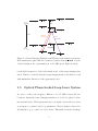
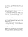
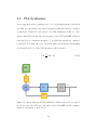
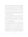
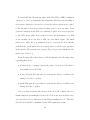
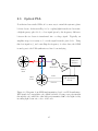
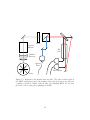
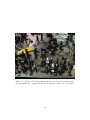
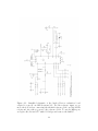
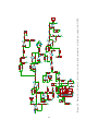
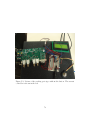
We designed a microcontroller-based solution for the programming of the current controller board, see Sec. 5. An ATmega328 microcontroller was used
for this board. The rotary encoder is attached to an external interrupt of the
microcontroller, allowing it to probe PB6 right away to check if the rotation
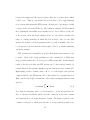
was clockwise or counterclockwise. A similar concept is used for reading out
the buttons. Each button press generates a hardware interrupt, which is when
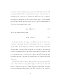
the microcontroller reads the status of the buttons to discover which one was
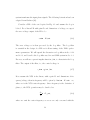
pressed. An LED display provides messages to the user through a Universal
Asynchronous Receiver/Transmitter (UART) protocol.
76