1
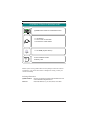
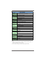
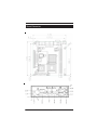
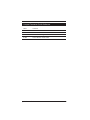
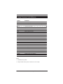
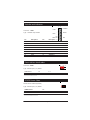
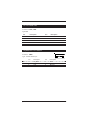
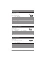
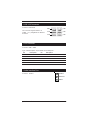
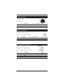
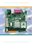
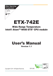
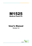
Quick Installation Guide
Version 1.0
(R)PEB-4702VLA
FORM FACTOR
CPU
CHIPSET
Mini-ITX
μFPGA 478
Pentium M
2.26 GHz
Intel 915GM
ICH6M
MEMORY
IDE
I/O
DDR2 2GB
1 x UDMA 100
2 x SATA
USB/Serial/LPT
Expansion Bus
LAN
AUDIO
PCI-Express x 16
Mini PCI
Dual Intel
PCI-Express
Giga LAN
AC'97 Codec
Copyright© 2005
All Rights Reserved.
The information in this document is subject to change without prior notice in
order to improve the reliability, design and function. It does not represent a
commitment on the part of the manufacturer.
Under no circumstances will the manufacturer be liable for any direct, indirect,
special, incidental, or consequential damages arising from the use or inability to
use the product or documentation, even if advised of the possibility of such
damages.
This document contains proprietary information protected by copyright. All rights
are reserved. No part of this manual may be reproduced by any mechanical,
electronic, or other means in any form without prior written permission of the
manufacturer.
About this Quick Installation Guide
This Quick Installation Guide provides general information and installation
instructions about the SBC. This User's Manual is intended for experienced
users and integrators with hardware knowledge of personal computers. If you
are not sure about any description in this User's Manual, please consult your
vendor before further handling.
2
Quick Installation
Warning
Single Board Computers and their components contain very delicate
Integrated Circuits (IC). To protect the Single Board Computer and its
components against damage from static electricity, you should always
follow the following precautions when handling it :
1. Disconnect your Single Board Computer from the power source when you
want to work on the inside
2. Hold the board by the edges and try not to touch the IC chips, leads or
circuitry
3. Use a grounded wrist strap when handling computer components.
4. Place components on a grounded antistatic pad or on the bag that came with
the Single Board Computer, whenever components are separated from the
system
Replacing the lithium batter
battery
Incorrect replacement of the lithium battery may lead to a risk of explosion.
The lithium battery must be replaced with an identical battery or a battery type
recommended by the manufacturer (BR2032).
Do not throw lithium batteries into the trashcan. It must be disposed of in
accordance with local requlations concerning special waste.
T echnical Suppor
Support
Please do not hesitate to call or e-mail our customer service when you still can
not find out the answer.
http://www.portwell.com
E-mail:[email protected]
Quick Installation
3
Warranty
This product is warranted to be in good working order for a period of two years
from the date of purchase. Should this product fail to be in good working order
at any time during this period, we will, at our option, replace or repair it at no
additional charge except as set forth in the following terms. This warranty does
not apply to products damaged by misuse, modifications, accident or disaster.
Vendor assumes no liability for any damages, lost profits, lost savings or any
other incidental or consequential damage resulting from the use, misuse of, or
inability to use this product. Vendor will not be liable for any claim made by any
other related party.
Vendors disclaim all other warranties, either expressed or implied, including but
not limited to implied warranties of merchantibility and fitness for a particular
purpose, with respect to the hardware, the accompanying product's manual(s)
and written materials, and any accompanying hardware. This limited warranty
gives you specific legal rights.
Return authorization must be obtained from the vendor before returned merchandise will be accepted. Authorization can be obtained by calling or faxing the
vendor and requesting a Return Merchandise Authorization (RMA) number.
Returned goods should always be accompanied by a clear problem description.
4
Quick Installation
(R)PEB-4702VLA PACKING LIST
(R)PEB-4702VLA Mini ITX Embedded board
1 x I/O Bracket
1 x CPU cooler or Heat Sink
1x ATX Power Cable 300mm
1 x CD-ROM (System Driver)
Quick Installation Guide
Warranty card
Before up and running, please make sure the package contains all of above
accessories. If any of the above items is damaged or missing, contact your
vendor immediately.
Ordering Information
(R)PEB-4702VLA
Cable Kit
Quick Installation
Mini-ITX Intel Pentium M socket 478 Embedded board with
CRT/LCD/DVI/Dual Gigabit Ethernet
IDE; USB; K/B-M/S; TV_Out; Print; SATA; LPT to FDD
5
Specification
(R)PEB-4702VLA
Product Name
Form Factor
Mini-iTX Embedded Board Size (170mm x 170mm)
Processor
μ FC-PGA478 pin Pentium-M Dothan Up to 2.26GHz(533MHz FSB)
Chipset
NB : Intel 915GM SB: Intel ICH6M
System Memory
Support Two 240Pin DDRII SDRAM DIMM Socket Up to 2GB
VGA/LCD Controller
UMA 915GM Video Controller with DVI, LVDS, TV-out and CRT support
(Support Dual Independent display)
Ethernet
Dual Intel 82573V Gigabit Ethernet
I/O Chips
WINBOND W83627HG
BIOS
Phoenix-Award PnP Flash BIOS
Audio
AC'97 Codec, supports MIC-In/ Line-In/ Line-out
Serial ATA
2 x Serial ATA with 150MB/s transfer rate
ATA / IDE
1 x Ultra DMA 100, support 2 IDE devices
Flash Disk
1 x Type II Compact Flash Disk Socket (Share IDE Resource)
Serial Port
COM 1: RS-232
2 x COM ports
COM 2: RS232/422/485 Select
Parallel Port
Supports SPP/ EPP/ ECP mode
K/B and Mouse
1 x PS2 K/B and Mouse
USB Port
8 x USB 2.0
DIO
8 bit programmable Digital I/O
TV out
6 pin mini wafer
LCD
18/36 bit LVDS
Expansion Interface
PCI-Express x 16 slot for High-Performance Graphics Card or PCI-Express
x1 Device
1 x Mini PCI socket
Hardware Monitor
Chip
RTC
Integrated in W83627HG
Support Real Time Clock
Power Input
Connector
ATX 12V Power Connector
Operation Temp.
0ºC ~ 60ºC
Watchdog Timer
255-level Reset
Dimension (L x W)
170 x 170 mm (6.7" x 6.7")
DC-IN 12V Power Adapter
Note:
1. Recommend use ATX power to instead of 12V DC-IN if there's a PCI
Express x16 Graphics card on the board
2. DC-12V Output: Strongly recommend output upper then 80W
6
Quick Installation
Board Layout
JFSB1
Quick Installation
7
Board Dimension
8
Quick Installation
Jumper/Connector Quick Reference
Label
Function
JBAT1
Clear CMOS
JRS1
COM2 RS-232/422/485 Select
JVLCD1
LVDS1 LCD Voltage select
JFSB1
Front side bus clock select
Quick Installation
9
Jumper/Connector Quick Reference
Label
Function
ATX12V1
ATX 12V DC Input
PWR1
4P Auxilary Power Connector (for output only)
AUDIO1
Audio interface Port
CPUF1
CPU FAN Connector
SYSF1
System FAN Connector
DIMM1,2
240 Pin DDR2 DIMM Socket
DIO1
Digital I/O Connector
IDE1
Primary IDE Connector
PCIE1
PCI Express x 16 Interface Slot
MPCI1
Mini PCI Interface
LVDS1
LVDS LCD Panel Connector
INV1
LCD Inverter Connector
IR1
Infrared (IR) Connector
TV1
TV-out Connector
SATA 1, 2
Serial ATA 1, 2 Connector
LPT1
Parallel Port or Floppy
CON1
RS-422 / 485 USB Connector
USB1, 2
USB Connector
KBM1
PS/2 Keyboard and Mouse
VGA1
CRT Display & DVI Connector
LAN1, LAN2
Ethernet ConnectorUSB1/2 + LAN1, LAN2 Connector
DCIN1
DC-12V Power Adapter In
JFRT1
Front Panel (Switches and Indicators)
CFD1
Compact Flash Socket
JPWR1
AT/ATX Power Type Selection
VGA1
CRT SVGA Connector
Note:
1. LPT/FDD select by BIOS
2. Compact Flash share by IDE1 resources,can not Hot swap
10
Quick Installation
CMOS Jumper Settings
CMOS Setup (JBAT1)
1 2 3
Type : JBAT1: Onboard 3-pin header
JBAT1
JBAT1
CMOS Setup (JBAT1)
Keep CMOS
1-2
ON
Clear CMOS
2-3
ON
Default setting
1-2
COM2 RS-232 / 422 / 485 Select
Connector: JRS1
5 3 1
Type: onboard 6-pin (2*3) header
JRS1
6 4 2
Mode Selection
1-2
3-4
5-6
RS-232
ON
OFF
OFF
RS-422
OFF
ON
OFF
RS-485
OFF
OFF
ON
Default setting RS-232
LCD Voltage Selection
1 2 3
Type : JVLCD1: Onboard 3-pin header
JVLCD1
The voltage of LCD panel could be selected by JVLCD1 in 5V or 3.3V.
Mode
3.3V
JVLCD1
2-3
5V
Default setting
1-2
2-3
Quick Installation
11
Switches and Indicators
1
PLED
Connector : JFRT1
Type : Onboard 16-pin header
HLED
2
+
+
-
-
-
+
+
-
-
+
CLK
SMB DAT
+
G
-
Pin
Description
Pin
1
Power LED+
2
Description
PWRBTN+
3
GND
4
PWRBTN-
5
GND
6
RESET+
7
HDD LED+
8
RESET-
9
HDD LED-
10
SPEAKER+
11
SMBCLK
12
SPEAKER+
13
SMBDATA
14
SPEAKER-
15
GND
16
SPEAKER-
-
PWRBTN
RESET
SPK
Front side bus clock select
1
Connector: JFSB1
Type: onboard 3-pin (1*3) header
2
3
JFSB1
JFSB1Select
1-2
2-3
Front side bus
400MHz
533MHz
Default setting:400MHz
AT/ATX Power Select
AT/ATX Power Selection(JPWR1)
Type: onboard 2-pin (1*2) header
JPER11Select
1-2
AT-MODE
SHORT
ATX-MODE
OPEN
JPWR1
Default setting:ATX MODE
12
Quick Installation
RS-232 Serial Port
Connector: COM1, COM2
Type: DB9
Pin
Description
Pin
Description
1
DCD1
2
RXD1
3
TXD1
4
DTR1
5
GND
6
DSR1
7
RTS1
8
CTS1
9
RI1
Keyboard & PS/2 Mouse
Connector : KBM1
6
1
Type : onboard waver 6-pin
Pin
Description
Pin
Description
1
3
5
KB_DATA
MS_DATA
VCC
2
4
6
GND
KB_CLK
MS_CLK
Quick Installation
13
TV-out Connector
Connector : TV1
1
6
Type: Onboard 6-pin wafer
Pin
Description
1
TV-CVBS
2
GND
3
TV_Y
4
GND
5
TV_C
6
GND
LCD Inverter Connector
Connector : INV1
1 2 3 4 5
Type : Onboard 5-pin wafer
Pin
Description
Pin
Description
1
+12 V
2
GND
3
Backlight on/off
4
Brightness control
5
GND
Infrared Connector
Connector : IR1
Type : onboard 2.54pitch 5-pin header
14
Pin
Description
1
+5v
2
NC
3
IRRX
4
GND
5
IRTX
1 2 3 4 5
IR1
Quick Installation
LVDS LCD Connector
Connector : LVDS1
30
2
29
1
Type : Onboard DF-13-30DP-1.25V
Pin
Description
Pin
1
VDD
2
Description
VDD
3
TX1CLK+
4
TX2CLK+
5
TX1CLK-
6
TX2CLK-
7
GND
8
GND
9
TX1D0+
10
TX2D0+
11
TX1D0-
12
TX2D0-
13
GND
14
GND
15
TX1D1+
16
TX2D1+
17
TX1D1-
18
TX2D1-
19
GND
20
GND
21
TX1D2+
22
TX2D2+
23
TX1D2-
24
TX2D2-
25
GND
26
GND
27
NC
28
NC
29
NC
30
NC
VDD could be selected by JVLCD1 in +5V or +3.3V
RS422/485 Output Connector
1 2 3 4
Connector: CON1
Type: onboard 2.0 pitch 4-pin wafer
Pin
RS-422
RS-485
1
TX+
DATA+
2
TX-
DATA-
3
RX+
N.C
4
RX-
N.C
CON1
RS-422/RS-485 Select by JRS1, share COM2 resource.
Quick Installation
15
Parallel Port Connector
Connector: LPT1
Type: onboard 2*10pin 2.0mm Box header
19
1
2
Pin
Description
Pin
20
Description
1
STROBE
2
AFD
3
PTD0
4
ERROR
5
PTD1
6
INIT
7
PTD2
8
SLIN
9
PTD3
10
GND
11
PTD4
12
GND
13
PTD5
14
Key(N/C)
15
PTD6
16
BUSY
17
PTD7
18
PE
19
ACK
20
SELECT
Floppy Drive Connector
LPT1 can be configured as a connector of floppy disk drive interface through
BIOS setup
Type: onboard 20-pin 2.0mm Box header
Pin
Description
Pin
Description
1
NC
2
RWC-
3
RINDEX-
4
HEAD-
5
TRAK0-
6
DIR-
7
WP-
8
STEP-
9
RDATA-
10
GND
11
DSKCHG-
12
GND
13
NC
14
Key(N/C)
15
PE
16
MOB-
17
DSA-
18
WD-
19
DSB-
20
WE-
16
Quick Installation
USB/ LAN Connector
Connector: LAN1/LAN2
LAN2
This connector supports USB 2.0 x4
(USB0, 1, 2, 3) & Gigabit RJ-45 Ethernet
Connector.
LAN1
USB
USB
USB
USB
USB Connector
Connector: USB1 / USB2
Type: onboard 2.54pitch 10-pin header for two USB ports
Pin
Description
Pin
Description
1
+5V
2
+5V
3
USBD-
4
USBD-
5
USBD+
6
USBD+
7
GND
8
GND
9
GND
10
N.C
Audio Interface Port
Connector : AUDIO1
Audio-In
Audio-Out
MIC-In
Quick Installation
17
DC Power Input
1
Connector : DCIN1
Type : Mini DIN
2
4
3
Pin
Description
Pin
Description
1
+12V
2
+12V
3
GND
4
GND
Power Connector
3
ATX Power Connector: ATX12V1
Type:12V 4-pin (2*2) Power Connector
Pin
Description
Pin
Description
4
+12V
2
GND
3
+12V
1
GND
4
Output Power Connector
PW R 1
Connector : PWR1 (Output Only)
Type : Onboard 4-pin Wafer connector
18
Pin
Description
1
+12V (2A)
2
GND
3
GND
4
+5V (3.5A)
+5 V
GND
GND
+12 V
Quick Installation
CPU / System Fan Connector
123
Connector : CPUF1 / SYSF1
Type : Onboard 3-pin wafer connector
Pin
CPUF1
Description
1
GND
2
+12V
3
Fan_Detect
Digital I/O Connector
Connector: DIO1
Type: onboard 2.54pitch 2*5-pin header
Pin
Description
Pin
Description
1
DIO1
2
DIO2
3
DIO3
4
DIO4
5
DIO5
6
DIO6
7
DIO7
8
DIO8
9
+5V
10
GND
Serial ATA
Connector: SATA1 / SATA2
High speed transfer rates (150MB/sec), support SATA RAID function.
Type: Standard 7-pin SATA Connector
Pin
Description
1
GND
2
TX+
3
TX-
4
GND
5
RX+
6
RX-
7
GND
Quick Installation
19
IDE Connector
Connector : IDE1
Type: onboard standard 2.54pitch
(2*20) 40-pin holes
Pin
Description
Pin
Description
1
IDE RESET
2
GND
3
DATA7
4
DATA8
5
DATA6
6
DATA9
7
DATA5
8
DATA10
9
DATA4
10
DATA11
11
DATA3
12
DATA12
13
DATA2
14
DATA13
15
DATA1
16
DATA14
17
DATA0
18
DATA15
19
GND
20
N.C
21
REQ
22
GND
23
IO WRITE
24
GND
25
IO READ
26
GND
27
IO READY
28
IDESEL
29
DACK
30
GND
31
IRQ14
32
N.C
33
ADDR1
34
ATA66 DETECT
35
ADDR0
36
ADDR2
37
#CS0
38
#CS1(#HD SELET1)
39
IDEACTP
40
GND
20
Quick Installation
Compact Flash Connector
Conntecor: CFD1
Pin
Description
Pin
Description
1
GND
26
GND
2
DATA3
27
DATA11
3
DATA4
28
DATA12
4
DATA5
29
DATA13
5
DATA6
30
DATA14
6
DATA7
31
DATA15
7
CS#1
32
CS#3
8
GND
33
GND
9
GND
34
IO READ
10
GND
35
IO WRITE
11
GND
36
+5V
12
GND
37
IRQ15
13
+5V
38
+5V
14
GND
39
CSEL
15
GND
40
N/C
16
GND
41
IDE RESET
17
GND
42
IO READY
18
ADDR2
43
N/C
19
ADDR1
44
+5V
20
ADDR0
45
DASP
21
DATA0
46
DIAG
22
DATA1
47
DATA8
23
DATA2
48
DATA9
24
N/C
49
DATA10
25
GND
50
GND
Note:
Compact Flash share by IDE1 resources, can not Hot swap
Quick Installation
21