1
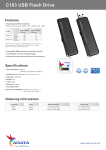
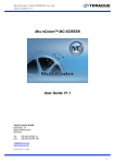
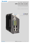
ArgoNavis QA/QC Decoder
User Manual and Installation Guide
ArgoNavis
Decoder
Installation
and
User Guide
Version 10.0.12.x
Page | 1
ArgoNavis QA/QC Decoder
User Manual and Installation Guide
Introduction ........................................................................................................................ 4
Special Notes on the Touch Screen .................................................................................... 4
Physical Connections .......................................................................................................... 4
Decoder Pro Model Rear Panel label .............................................................................. 4
Decoder Pro Model Connection Diagram ....................................................................... 5
Decoder Pro Model Connector Table ............................................................................. 5
Decoder Pro Model Breakout Cable Pinout.................................................................... 6
Decoder SDI Model Rear Panel Label ............................................................................. 7
Decoder SDI Model Connection Diagram ....................................................................... 7
Decoder SDI Model Connector Table ............................................................................. 7
Decoder Analog and HDMI Model Rear Panel Label ...................................................... 8
Decoder Analog and HDMI Model Connection Diagram ................................................ 8
Decoder Analog and HDMI Model Connector Table ...................................................... 8
System Specifications.......................................................................................................... 9
ArgoNavis Operations ....................................................................................................... 10
Launching the Application ............................................................................................ 10
Some Basic Settings ...................................................................................................... 11
Configuring the Output Resolution ........................................................................... 11
Playlist Operations ........................................................................................................ 12
Add a Clip to the Playlist ........................................................................................... 12
Creating a Playlist ...................................................................................................... 13
Saving a Playlist ......................................................................................................... 13
Clearing the Listview ................................................................................................. 13
Recalling a Saved Playlist .......................................................................................... 13
Decoder Controls and Keyboard Shortcuts .................................................................. 14
Stop
.................................................................................................................. 14
Play / Pause
Frame Advance
......................................................................................... 14
................................................................................................ 14
Frame Reverse
.................................................................................................. 14
Track Bar ................................................................................................................... 14
Jump
............................................................................................................ 15
Local Audio Rendering .............................................................................................. 15
Special Controls............................................................................................................. 16
Audio Display Window .............................................................................................. 16
Alarm Details Window .............................................................................................. 17
File Information/Parse .............................................................................................. 19
Closed Captioning Display Window .......................................................................... 20
Playback Properties and Graphics Overlay Settings ..................................................... 21
Page | 2
ArgoNavis QA/QC Decoder
User Manual and Installation Guide
608 Captioning Overlay............................................................................................. 21
708 Captioning Overlay............................................................................................. 22
Video Background Color ........................................................................................... 22
Action\Title Safe Area Overlay.................................................................................. 22
Timecode Overlay ..................................................................................................... 22
Use 1080P not 1080PsF ............................................................................................ 22
Use Alternate SD MPEG Decoder ............................................................................. 23
Deinterlacing Mode HD............................................................................................. 23
Enforce Field Ordering for HD Source....................................................................... 23
Deinterlacing Mode SD ............................................................................................. 23
Enforce Field Ordering for SD Source ....................................................................... 24
Enable VANC Insertion .............................................................................................. 24
Use Drop Frame for Timecodes ................................................................................ 24
Use GOP Header Time Code on location bar ............................................................ 24
AC3 Bitstream Out Enabled ...................................................................................... 24
Disable .info Files ...................................................................................................... 25
Append .SLT Files if Available.................................................................................... 25
Duration Between Clips ............................................................................................ 25
Enable LKFS Checks in the Playlist ............................................................................ 25
Clear All Values When Media Starts ......................................................................... 26
Exclude LKFS Measurement on Silence .................................................................... 26
Reset Integrated Value on Silence ............................................................................ 26
Exiting the Application .................................................................................................. 27
Page | 3
ArgoNavis QA/QC Decoder
User Manual and Installation Guide
Introduction
Vela Research is pleased to introduce the ArgoNavis Decoding System. The ArgoNavis
provides advanced, multiformat decoding and playback capabilities supporting MPEG-2,
h.264 (AVC) and other video compression technologies contained within many different
multiplexed containers, such as MPEG-2 TS, MPEG-2 PS, MP4 and QT formats.
Special Notes on the Touch Screen
If equipped with a Touch Screen, after unit power up, please allow several seconds for
the Touch Screen drivers to load prior to ‘touching’ the Touch Screen.
The Touch Screen is controlled via USB. Included with the Touch Screen is a USB cable.
Connect the USB cable from the Touch Screen to any available USB connector on the
ArgoNavis unit.
Physical Connections
Note that the ArgoNavis platform can be configured as an encoder or decoder and the
inputs and outputs will be enabled/disabled based upon the configuration of the unit.
For example, an encoder only unit will have only the inputs enabled. Likewise, the
decoder only configuration will have only the outputs enabled.
The ArgoNavis system comes in three different input/output configurations:
Decoder Pro Model Rear Panel label
4000-xxxx-3 ArgoNavis Decoder Pro
A
B
A – HD/SD SDI IN
B – HD/SD SDI OUT
HDMI IN
Page | 4
MULTI I/O
PORT
HDMI OUT
ArgoNavis QA/QC Decoder
User Manual and Installation Guide
Decoder Pro Model Connection Diagram
Decoder Pro Model Connector Table
Connectors
SDI Video Output
Component Video Output
Composite Video Output
S-Video Output
HDMI Video Output
Analog Audio Output
AES/EBU Audio Output
SDI Audio Output
HDMI Audio Output
Sync Input
Device Control
Page | 5
HD/SD Switchable 75 ohm BNC
Y, Pb, Pr on 3 BNC
BNC
S-Video Connector
HDMI type A Connector
4 Channels via ¼” jack connectors. Jack connector is
TRS (Tip, Ring, Sleeve) Balanced 110 ohm at +4 dBm
reference level.
2 Channels Unbalanced 75 ohm BNC
8 Channels Embedded in HD or SD
2 Channels Embedded in HD or SD
75 ohm BNC. Blackburst in PAL and NTSC formats or
Tri Level Sync in any format.
Sony compatible RS422 deck control.
ArgoNavis QA/QC Decoder
Decoder Pro Model Breakout Cable Pinout.
Page | 6
User Manual and Installation Guide
ArgoNavis QA/QC Decoder
User Manual and Installation Guide
Decoder SDI Model Rear Panel Label
4000-xxxx-2 ArgoNavis Encoder HD/SD SDI
A
B
C
A – GEN LOCK IN
B – SD SDI
C – HD/SD SDI
MULTI I/O
PORT
Decoder SDI Model Connection Diagram
Decoder SDI Model Connector Table
Connectors
SDI Video Output
Sync Input
Device Control
Page | 7
HD/SD Switchable 75 ohm BNC
75 ohm BNC. Blackburst in PAL and NTSC formats or
Tri Level Sync in any format. Not Used on the Encoder.
Sony compatible RS422 deck control.
ArgoNavis QA/QC Decoder
User Manual and Installation Guide
Decoder Analog and HDMI Model Rear Panel Label
4000-xxxx-1 ArgoNavis Encoder Analog and HDMI
A
B
A – HDMI IN
B – HDMI OUT
MULTI I/O
PORT
Decoder Analog and HDMI Model Connection Diagram
Decoder Analog and HDMI Model Connector Table
Connectors
Component Video Output
Composite Video Output
Analog Audio Output
HDMI Video Output
HDMI Audio
Page | 8
3 x RCA Connector
1 x RCA Connector
2 x Unbalanced RCA Connector. 1 Stereo Pair
1 x HDMI Type A Connector
2 Channels Embedded in HDMI
ArgoNavis QA/QC Decoder
User Manual and Installation Guide
System Specifications
Chassis
Model: 4000-2187-x (1.5 U Rackmount)
Dimensions: (WxHxD) 16.8 x 2.6 x 13 in. (427 x 66 x 330 mm)
Weight
Gross Weight: 19.6 lbs. (8.9 kg.)
System Input Requirements
AC Input Voltage: 100-240V AC auto-range, 5A, 50 – 60 Hz
Power Supply
Rated Output Power: 220W
Rated Output Voltages: +3.3V (0 to 10A), +5V (12A), +12V (16A), -12V (0.3A), +5Vsb (0
to 2A), +5V and +3V total 80W max.
Operating Environment
Operating Temperature: 10° to 35° C (50° to 95° F)
Non-operating Temperature: -40° to 70° C (-40° to 158° F)
Operating Relative Humidity: 8% to 90% (non-condensing)
Non-operating Relative Humidity: 5 to 95% (non-condensing)
Drive Bays
2 x 3.5” Internal SATA drive bays
Note: The following items are subject to change based on configuration, part
availability/obsolescence, and technological advances.
Motherboard
MSI Model: H67MA-E35
Supports LGA1155 processors
Supports RAID 0, 1, 5, 10 on MotherBoard
Processor (s)
1 Intel i5 2400 3.1 GHz Quad Core Processor (can be upgraded)
HDD
1 x 2 TB 3.5” 7200 RPM SATA (can be upgraded)
OS
Windows 7 Professional 32 Bit
Page | 9
ArgoNavis QA/QC Decoder
User Manual and Installation Guide
ArgoNavis Operations
Launching the Application
The application can be launched from the Vela Toolbar (shown below) which will launch
automatically at startup and be positioned on the right hand side of the desktop.
Or the application can be launched from the Windows Start menu by selecting the start
icon
Decoder’.
Page | 10
, then select ‘All Programs’, ‘Vela Research’, ‘ArgoNavis’, ‘ArgoNavis
ArgoNavis QA/QC Decoder
User Manual and Installation Guide
Some Basic Settings
Configuring the Output Resolution
By default the Output Resolution is set to Auto-Scale mode. In Auto-Scale mode the
output resolution is automatically set to the native resolution of the file being played
back.
If you wish to take the unit out of Auto-Scale mode, select the Output Resolution drop
down menu and ‘uncheck’ Auto-Scale. Then select the Output Resolution you desire.
When in any resolution other than Auto-Scale the output resolution of the decoder is
constant regardless of the resolution of the file being played back. For example if the
‘Output Resolution’ is set to 1920 x 1080i then any file played back will be output as
1920 x 1080i.
Auto-Scale On
File Resolution
1920x1080i
720x480i
Output Resolution
1920x1080i
720x480i
Auto-Scale Off with Resolution set to 1920 x 1080i
File Resolution
Output Resolution
1920x1080i
1920x1080i
720x480i
1920x1080i
Page | 11
ArgoNavis QA/QC Decoder
User Manual and Installation Guide
Playlist Operations
Add a Clip to the Playlist
1. Select one of the ‘Browse’ buttons (see above) and browse for the file.
2. Once in the ‘Browse’ window the file can be added using the ‘Open’ button or
individual or multiple files can be ‘dragged and dropped’ into the playlist.
3. Repeat steps 1 and 2 as necessary.
4. Keyboard Shortcut to load a clip: CTRL + L
5. Keyboard Shortcut to unload a clip: CTRL + U
Page | 12
ArgoNavis QA/QC Decoder
User Manual and Installation Guide
Creating a Playlist
Playlist Controls from left to right are:
Load List
Save Playlist
Clear Playlist
Remove Clip from Playlist
1. Select the ‘Add Clip’ button to add clips to the Playlist
2. The file browser will allow you to select multiple clips at once for import into the
playlist.
3. Once imported clips can be repositioned within the list by dragging them up or
down the list.
4. To remove a clip highlight one or multiple clips and select ‘Remove Clip’.
Saving a Playlist
1. Select the ‘Save List’ button
2. A file save browser will open. Save the playlist file.
3. Playlist files are saved in an XML format. We recommend that you do not use
spaces in playlist file names. Use underscores where spaces would be. For
example instead of List 1.xml, use List_1.xml.
4. Playlist files can be edited outside of PlayAdvantage using a simple text editor
such as notepad.
Clearing the Listview
1. Individual Clips can be removed from the playlist listview using the ‘Remove Clip’
button.
2. The entire playlist listview can be cleared using the ‘Clear List’ button.
Recalling a Saved Playlist
1. Select ‘Load List’
2. Browse for and open the saved playlist.
3. Once loaded the list can be played or modified.
Page | 13
ArgoNavis QA/QC Decoder
User Manual and Installation Guide
Decoder Controls and Keyboard Shortcuts
Stop
1. Stops decoder Playback.
Play / Pause
1. Initiates playback.
2. When playing, Pauses playback
3. Keyboard Shortcut: Space bar
Frame Advance
1. Advances the clip one frame.
2. Keyboard Shortcut: Right Arrow
Frame Reverse
1. Rewinds the clip one frame.
2. Keyboard Shortcut: Let Arrow
Track Bar
1. Allows you to quickly jump/move around within the file.
2. Displays the current position of playback.
3. Displays the current Timecode and the total duration of the file.
Page | 14
ArgoNavis QA/QC Decoder
User Manual and Installation Guide
Jump
Allows you to jump to a particular timecode within the file.
1.
2.
3.
4.
Click ‘JUMP’ to open the jump menu (or Keyboard Shortcut: CTRL+J)
Input a valid timecode in HH:MM:SS:FF format
Click ‘Jump To:’ to execute the jump (or Keyboard Shortcut: Enter)
Click ‘JUMP’ to close the jump menu
Keep window open after jump: If checked the Jump window will remain open after the
jump has been executed. If unchecked the window will automatically close on jump.
Local Audio Rendering
The Local Audio Rendering allows you to select from up to eight (8) audio channels and
render the audio to local speakers (computer speakers) connected to the PC or an HDMI
monitor connected to the PC portion of the system. Select the channel(s) you wish to
hear by clicking on Ax.
Note that since the computer system or HMDI typically has only two speakers all of the
channels are downmixed in the following order:
A1
Left
A2
A3
Right Left
Page | 15
A4
A5
Right Left
A6
A7
Right Left
A8
Right
ArgoNavis QA/QC Decoder
User Manual and Installation Guide
Special Controls
CC:
LED:
Loop:
Info:
Opens the CC decode window (this window is opened by default on app
launch)
Opens the Alarm Details window (this window is opened by default on
app launch)
Loops the file
Opens the File Information/Parse window (this window is opened by
default on app launch)
Audio Display Window
The Audio Display Window contains the following elements:
1. Amplitude for each of up to eight channels
2. LKFS for each of two logical audio streams (up to six channels per stream)
a. MNT: The instantaneous/momentary LKFS measurement
b. SHR: The short term average measurement (3 second average per EBU
spec)
c. INT: The realtime integrated measurement. If the clip is played through
completely this value will be the integrated measurement for the entire
clip.
d. True Peak: The peak measurement obtained from all channels with a
logical audio stream.
3. Graph of Audio Amplitude for each channel over time
Page | 16
ArgoNavis QA/QC Decoder
User Manual and Installation Guide
Alarm Details Window
The Alarm Details window is designed to allow the operator to configure set points on
the following parameters:
Audio Levels for each channel
Audio LKFS for up to two logical audio streams (up to six channels each)
Closed Captioning detection
Sequential Black Frame detection
Configuring Audio Level and LKFS Alarm Set Points
Audio Level and LKFS alarm set points can be configured by performing the following.
1.
2.
3.
4.
5.
Click on the parameter you wish to configure such as
Set the High Threshold (in dBFS)
Set the Tolerance (how long the High Threshold must be exceeded in seconds)
Set the Low Threshold (in dBFS)
Set the Tolerance (how long the Low Threshold must be exceeded in seconds)
Once set the LED will indicate the current state of the alarm.
Green = No Alarm
Red = Alarm
Yellow = Alarm History
Page | 17
ArgoNavis QA/QC Decoder
User Manual and Installation Guide
Configuring Black and Closed Captioning Alarm Set Points
Black Frame detection and Closed Captioning Packet detection alarm set points can be
configured by performing the following.
1. Select the parameter you wish to configure
2. Set the number of frames before an alarm is declared
3. Optionally, set the Mark-In and Mark-Out where you wish to monitor for this
parameter. If no Mark-In and Mark-Out are set, then the entire file will be
monitored.
Page | 18
ArgoNavis QA/QC Decoder
User Manual and Installation Guide
File Information/Parse
This feature will display information about the file in the list. Once opened you can
select which file to show information about by selecting the drop down menu in the File
Information/Parse window (see below).
The types of information provided include:
Type of wrapper
Type of video compression
Video resolution
Chroma sampling
Video bitrate
GOP Structure
Type of audio compression
Audio sampling and bitrates
Number of Audio Channels
ATSC Closed Captioning information
Page | 19
ArgoNavis QA/QC Decoder
User Manual and Installation Guide
Closed Captioning Display Window
The Closed Captioning Display show 608, 708, and Line 21 closed captioning data while
providing an unobstructed view of the video display and audio level meters during
playback.
To Launch the CC viewer select the CC button, which is one of the Special Controls
buttons on the front panel of the ArgoNavis user interface. Note that this window is
launched automatically when the decoder application is launched
Page | 20
ArgoNavis QA/QC Decoder
User Manual and Installation Guide
Playback Properties and Graphics Overlay Settings
608 Captioning Overlay
The ArgoNavis can decode Line 21/608 closed captions and overlay them onto all video
outputs as open captions. Select the ‘608 Closed Captioning Overlay’ checkbox and then
select the Service Type to display (CC 1 is default)
Note: No other graphics overlay options can be selected when ‘Line 21 Closed
Captioning Overlay’ is enabled.
Page | 21
ArgoNavis QA/QC Decoder
User Manual and Installation Guide
708 Captioning Overlay
The ArgoNavis can decode 708 closed captions and overlay them onto all video outputs
as open captions. Select the ‘708 Captioning Overlay’ checkbox and then select the DTV
Service Type to display (Primary Caption Service is default)
Note: No other graphics overlay options can be selected when either ‘Closed Captioning
Overlay’ option is enabled.
Video Background Color
This tool allows the user to set a background color for the local video (PC) renderer.
This can be useful in viewing the differences between active and inactive video.
Note: The background color is only changed on the local video (PC) renderer. None of
the ‘decoder’ outputs such as SDI, Component, etc. are affected.
Action\Title Safe Area Overlay
The ArgoNavis can provide a graphic overlay of the Action and Title Safe areas. These
areas can be used to determine if video or graphics will be cutoff on CRT monitors.
By default these values are set to 5% and 15% respectively, but are user settable.
Note: Line 21 (608) and DTV (708) graphics overlay options cannot be selected when
the Action\Title Safe Area Overlay is enabled.
Timecode Overlay
The ArgoNavis can provide a graphic overlay of the current Timecode while playing a file
back
Note: Line 21 (608) and DTV (708) graphics overlay options cannot be selected when
the Timecode Overlay is enabled.
Use 1080P not 1080PsF
When ‘checked’ this setting forces the physical output to 1080P. When not checked the
physical output is forced to 1080PsF.
Page | 22
ArgoNavis QA/QC Decoder
User Manual and Installation Guide
Use Alternate SD MPEG Decoder
When ‘checked’ this setting uses a different MPEG decoder design to perform decoding.
This setting is ‘Unchecked’ by default. This setting provides an alternate decode
platform which can be useful in certain troubleshooting or debugging scenarios.
Deinterlacing Mode HD
Selects which Deinterlacing filter to use. Options are:
1.
2.
3.
4.
5.
Auto (Automatic deinterlace if picture type is field or MBAFF)
Weave (Do not deinterlace – output interleaved fields)
Vertical Filter Deinterlace (Vertical deinterlace)
Field Interpolation (Deinterlace by interpolation)
Rederer (No deinterlacing on the physical output)
Auto is the default setting.
Enforce Field Ordering for HD Source
This setting swaps the Field Ordering on the physical outputs and can be used to find
‘Field Ordering’ issues that result in a ‘jittery’ output. This setting should be used in
conjunction with:
1. Deinterlace Mode HD set to ‘Renderer’
2. Enable VANC Insertion ‘Checked’
Deinterlacing Mode SD
Selects which Deinterlacing filter to use. Options are:
1.
2.
3.
4.
5.
Auto (Automatic deinterlace if picture type is field or MBAFF)
Weave (Do not deinterlace – output interleaved fields)
Vertical Filter Deinterlace (Vertical deinterlace)
Field Interpolation (Deinterlace by interpolation)
Renderer (No deinterlacing on the physical output)
Auto is the default setting.
Page | 23
ArgoNavis QA/QC Decoder
User Manual and Installation Guide
Enforce Field Ordering for SD Source
This setting swaps the Field Ordering on the physical outputs and can be used to find
‘Field Ordering’ issues that result in a ‘jittery’ output. This setting should be used in
conjunction with:
1. Deinterlace Mode SD set to ‘Renderer’
2. Enable VANC Insertion ‘Checked’
Enable VANC Insertion
When ‘checked’ this 608/708 VANC data is inserted on the specified line.
HD VANC Line
Specifies the line to insert the CC data. Valid values are 9 through 16.
SD VANC Line
Specifies the line to insert the CC data. Valid values are 12 through 16.
Use Drop Frame for Timecodes
When ‘checked’ this drop frame timecodes are used for the trackbar and Time Code
Overlay.
Use GOP Header Time Code on location bar
When ‘checked’ the GOP Header timecode is used on the trackbar. If ‘unchecked’
timecode starts from 00:00:00:00
AC3 Bitstream Out Enabled
When ‘checked’ this setting bypasses decoding AC-3 and outputs the AC-3 embedded in
the SDI.
Page | 24
ArgoNavis QA/QC Decoder
User Manual and Installation Guide
Disable .info Files
By default the decoder creates a file that contains the mpeg parameters of media file
under test. This file is stored in the same location as the media file under test and is
used to ‘pre-configure’ the decoder if the file is loaded into the player again. Creating
and retaining this file is not required for decoder operations and can be disabled using
this setting.
Append .SLT Files if Available
For advertisements or spots that have slate files associated with them (.SLT) this feature
allows to the .SLT file to be loaded with the spot automatically.
Duration Between Clips
Sets the duration the decoder will wait between playback of clips in the playlist in
seconds.
In ‘Auto Detect’ mode the decoder resets the physical outputs to match the timing and
resolution of the file under test for each clip in the list. How long it takes for peripheral
SDI/HDMI monitors to resync after the switch can vary by manufacturer. This setting
allows you to extend the delay to allow more time for peripheral equipment to resync
after each resolution change.
Enable LKFS Checks in the Playlist
This feature allows the decoder to launch a file based, faster than realtime process in
background to analyze the loudness of media files loaded into the playlist per the ATSC
A/85 CALM Act specification.
LKFS Upper Limit:
Failure occurs above this value
LKFS Lower Limit:
Failure occurs below this value
LKFS True Peak Limit: Failure occurs above this value
Results are displayed in the Playlist below the clip name. A green check mark indicates
pass. A red X indicates fail.
Page | 25
ArgoNavis QA/QC Decoder
User Manual and Installation Guide
Clear All Values When Media Starts
When checked the final Realtime LKFS values will persist until the next clip is played.
Exclude LKFS Measurement on Silence
When checked silence will not be included in the Realtime LKFS Integrated
measurement.
Reset Integrated Value on Silence
When checked the Realtime LKFS value is reset whenever silence is encountered.
Page | 26
ArgoNavis QA/QC Decoder
User Manual and Installation Guide
Exiting the Application
Under normal conditions, shutdown the application using the windows x button.
Under abnormal conditions, select the Soft Reset option on the Vela Toolbar. This will
forcibly shutdown all Vela applications and threads and clear the programs from
memory.
Page | 27
ArgoNavis QA/QC Decoder
User Manual and Installation Guide
www.vela.com
5540 Rio Vista Drive
Clearwater, FL 33760-3107
727 507 5344
Copyright 2014 Vela Research LP. All rights reserved. Vela and
PlayAdvantage are trademarks or registered trademarks of Vela
Research LP.
Page | 28