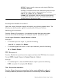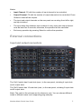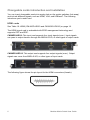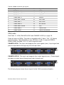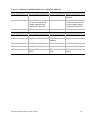
1
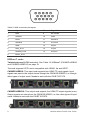
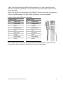
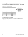
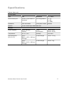
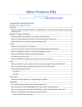
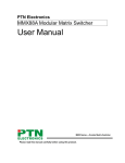
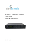
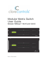
Modular Matrix Switch
User Guide
Models HDBaseT 16x16 and 32x32
2014-11-753 • Rev 01
Copyright
© 06NOV14 Clare Controls, Inc. All rights reserved.
This document may not be copied in whole or in part or
otherwise reproduced without prior written consent from
Clare Controls, Inc., except where specifically permitted
under US and international copyright law.
Trademarks and
patents
Modular Matrix Switches, Models CM-MM161610-HD and
CM-MM323210-HD name is a trademark of Clare
Controls, Inc.
Other trade names used in this document may be
trademarks or registered trademarks of the manufacturers
or vendors of the respective products.
Manufacturer
Version
Contact information
Clare Controls, Inc.
7519 Pennsylvania Ave., Suite 104
Sarasota, FL 34243, USA
This document applies to HDBaseT 16x16 and 32x32
Matrix Switches Models CM-MM161610-HD and
CM-MM323210-HD Rev 01.
For contact information, see www.clarecontrols.com.
Content
Important information...ii Limitation of liability...ii Introduction...1 About the switch system...1 Features...1 Package contents...2 Switcher models...2 Signal cards...2 Front panel...3 Front panel button control...4 External connections...5 Input and output connectors...5 Changeable cards introduction and installation...6 Connecting with the RS-232 communication port...10 Connecting with a computer...10 System diagram...11 IP and RS-232 control protocol...12 Detailed examples...15 Specifications...17 Changeable cards...18 Troubleshooting and maintenance...20 Safety operation guide...21 After-sales service...22 Modular Matrix Switch User Guide
i
Important information
Limitation of liability
To the maximum extent permitted by applicable law, in no event will Clare
Controls, Inc. be liable for any lost profits or business opportunities, loss of use,
business interruption, loss of data, or any other indirect, special, incidental, or
consequential damages under any theory of liability, whether based in contract,
tort, negligence, product liability, or otherwise. Because some jurisdictions do
not allow the exclusion or limitation of liability for consequential or incidental
damages the preceding limitation may not apply to you. In any event the total
liability of Clare Controls, Inc. shall not exceed the purchase price of the
product. The foregoing limitation will apply to the maximum extent permitted by
applicable law, regardless of whether Clare Controls, Inc. has been advised of
the possibility of such damages and regardless of whether any remedy fails of
its essential purpose.
Installation in accordance with this manual, applicable codes, and the
instructions of the authority having jurisdiction is mandatory.
While every precaution has been taken during the preparation of this manual to
ensure the accuracy of its contents, Clare Controls, Inc. assumes no
responsibility for errors or omissions.
ii
Modular Matrix Switch User Guide
Introduction
About the switch system
The HDBaseT 16x16 and 32x32 matrix switches are high-performance video and
audio modular matrix switches. Various changeable cards make matrix switches
flexible and an all-in-one solution for different projects. The matrix switches can
support different video signals with cross switching. Every video or audio signal is
transmitted and switched independently; this will cause the least signal attenuation,
so that the output signal keeps its high fidelity.
Two series of changeable cards work with matrix switches, input card MOD-4I series
and output card MOD-4O series. All the cards support hot plug-and-play. Users can
choose the right card for different applications. Different signal cards are used for
processing different video signal, including HMDI, VGA, and HDBaseT.
The matrix switches can be used for different projects, because of the changeable
card design. It is the combination solution for multimedia conference rooms, control
rooms, broadcasting rooms, and shopping centers. The matrix switches can handle
all the audio and visual management, including the switching, driving, and scaling.
Features
•
Modular chassis with configurable I/O slots, ranging from 16x16 to 32x32
•
Various I/O cards, includes HDMI, VGA, and HDBaseT cards (compatible with
YUV, YC and CVBC) to configure any matrix
•
True cross-point switching for any input to any output, regardless signal format
•
Advanced EDID management, three ways to guarantee maximum compatibility
•
Supports HDMI 1.4a and 3D
•
Integrated HDBaseT technology
•
I/O cards works directly with CATx or a fiber optic extender
•
Ultra-switching for an instantaneous display, ensuring the transition runs
smoothly
•
Unique pixel-accurate and re-clocking technology provides exceptional output
transmission and accurate timing
•
Controlled via buttons, RS-232, TCP/IP, IR, also compatible with third-party
controls
•
Field-upgradeable and hot-swappable, friendly to use and maintain
•
HDCP compliant
•
LCD display
Modular Matrix Switch User Guide
1
Package contents
•
1 x modular matrix switch (with empty slots and empty covers)
•
1 x RS-232 cable
•
1 x IR remote (battery is not included)
•
2 x power cord
•
4 x plastic cushions
•
1 x user manual
Switcher models
Table 1: Title of the table
Model
Height
Maximum slot
Power
supplies
RS-232
control
Network
control
16x16
3U
4 input card slots and
4 output card slots
Dual
√
Optional
32x32
5U
8 input card slots and
8 output card slots
Dual
√
Optional
Signal cards
To meet different situation and users, the signal cards are classified into the
following models.
Input cards
Table 2: Input cards
Models
Inputs
Signal Format
CM-MOD-HDI10
4
HDMI
CM-MOD-VGI10
4
VGA
CM-MOD-HDBI10
4
HDBaseT
2
Modular Matrix Switch User Guide
Table 3: Output cards
Models
Outputs
Signal Format
CM-MOD-HDO10
4
HDMI
CM-MOD-VGO10
4
VGA
CM-MOD-HDBO10
4
HDBaseT
Front panel
The 16x16 and 32x32 switches share the same function buttons, but only differ in
case height.
(1)
(2)
(3)
(4)
(5)
(6)
(1)
Power indicator
Power 'on' indicator light.
(2)
IR receiver
IR receive window.
(3)
LCD indicator
Shows real-time system status.
(4)
INPUTS
Allows direct selection of the input channel from 1 to 16 or
1 to 32.
(5)
OUTPUTS
Allows direct selection of the output channel from 1 to 16 or
1 to 32.
(6)
FUNCTION
GLOBAL: Used to transfer video and audio signal (HDMI) of an
input channel to all output channels.
Example: To transfer HDMI signal from input channel 7 to all
output channels, press the buttons as follows: Input “0” “7” +
“GLOBAL” + “Select”.
EDID: Used to manually control EDID management.
Example: To learn the EDID data of the display on output
channel 2 to input channel 3, press the buttons as follows:
"EDID" + Input "0" "3" + Output "0" "2".
Modular Matrix Switch User Guide
3
SELECT: Used to transfer video and audio signal (HDMI) from
an input to an output.
Example To transfer both the video and audio signals from input
channel 3 to output channel 4, press the buttons as follows:
Input “0” "3" + Output “0” "4" + "SELECT".
CLEAR: Clear an operation, such as switching output channel,
studying EDID data before it comes into effect. Meanwhile, the
switcher returns to the previous state.
Front panel button control
Users can control the switch rapidly and directly using its front panel buttons. The
following is a brief operation guide to operating the front panel buttons.
Switching I/O connection
Function: Switch I/O connection. It is important to know that input and output
channels should be double-digit. For example, input 01 represents input 1.
Format: Input Channel + Output Channel + Select
Examples
•
To transfer input 1 to output 11, press the following.
(input) 0 1 + (output) 1 2 + Select.
•
To transfer signals from input 1 to all output channels, press the following.
0 1 + Global + Select.
EDID Management
Function: Enable the input channel to capture and learn the EDID data of an output.
Format: EDID + Input Channel + Output Channel + Select
Example
•
To enable input 1 to learn the EDID data of output 2, press the following.
EDID + (input) 0 1 + (output) 0 2 + Select.
Clear the previous operation
Function: Clears the previous operations before pressing Select to enforce it.
Pressing Clear only erases the operations not confirmed by pressing Select.
4
Modular Matrix Switch User Guide
Notes
•
Input Channel: Fill with the number of input channel to be controlled,
•
Output Channel: Fill with the number of output channels to be controlled. Press
Global to select all the outputs.
•
The input and output channels on the rear panel are counting from left to right,
and top to bottom.
•
The input delay time between two numbers of every input and output channel
must be less than 5 seconds; otherwise, the operation will be cancelled.
•
End every operation by pressing Select to confirm the operation.
External connections
Input and output connectors
The 16x16 switch has 8 card slots (max.) in the rear panel, including 4 input slots
and 4 output slots.
The 32x32 switch has 16 card slots (max.) in the rear panel, including 8 input slots
and 8 output slots.
Note: The cards in the pictures are for reference, only. You can choose different
cards in different cases, each supporting plug-and-play.
Modular Matrix Switch User Guide
5
Changeable cards introduction and installation
You can insert changeable cards into empty slots on the matrix switches (hot-swap)
and include different signals, such as HDMI, VGA, and HDBaseT. The following
introduces you to each card.
HDMI cards
See Table 10: HDMI (CM-MOD-HDI10 and CM-MOD-HDO10) on page 18.
The HDMI signal card is embedded with EDID management technology and
supports CEC and DDC.
CM-MOD-HDI10: This input card supports four input signals (max.). Input signals
can pass to output devices through the MMX-4O-HD, or other types of output cards.
CM-MOD-HDO10: This output card supports four output signals (max.). Output
signals can come from MMX-4I-HD, or other types of input cards.
The following figure shows the pin layout for the HDMI connectors (female).
6
Modular Matrix Switch User Guide
Table 4: HDMI connector pin layout
Pin
Signal Name
Pin
Signal Name
1
TMDS Data 2+
20
SHELL
2
TMDS Data 2 Shield
19
Hot Plug Detect
3
TMDS Data 2-
18
+5V Power
4
TMDS Data 1+
17
Ground
5
TMDS Data 1 Shield
16
DDC Data
6
TMDS Data 1-
15
DDC Clock
7
TMDS Data 0+
14
No Connect
8
TMDS Data 0 Shield
13
CEC
9
TMDS Data 0-
12
TMDS Clock-
10
TMDS Clock+
11
TMDS Clock Shield
VGA cards
See Table 11: VGA (CM-MOD-VGI10 and CMMOD-VGO10) on page 18.
Scale all inputs to 1080p. The card is compatible with C-Video, YUV, YC (factory
preset function). The bandwidth is up to 350 MHz (-3 dB). It supports RGBHV,
RGsB, RGBS, RsGsBs, YUV, YC and Composite video.
CM-MOD-VGI10: This input card supports four input signals (max.). Input signal can
pass to output device through any kind of output card.
CM-MOD-VGO10: This input card supports four output signals (max.). Output signal
can pass to output device through any kind of output card.
The following figure shows the pin layout for the VGA connectors (female).
Modular Matrix Switch User Guide
7
Table 5: VGA connector pin layout
Pin
Signal Name
Pin
Signal Name
1
RED
9
KEY/PWR
2
GREEN
10
GND
3
BLUE
11
ID0/RES
4
ID2/RES
12
ID1/SDA
5
GND
13
HSync
6
RED_RTN
14
VSync
7
GREEN_RTN
15
ID3/SCL
8
BLUE_RTN
HDBaseT cards
Twisted pair card (HDMI extender). See Table 12: HDBaseT (CM-MOD-HDBI10
and CM-MOD-HDBO10) on page 19.
The card supports HDTV and is compatible with HDMI 1.4a and HDCP.
CM-MOD-HDBI10: This input card supports four HDMI TP input signals. Input
signals can pass to the output device through the CM-MOD-HDBO10, or through
other types of output cards. Needs to work with the CM-BT10-TX70.
CM-MOD-HDBO10: This output card support four HDMI TP output signals (max.).
Output signals can come from the CM-MOD-HDBI10, or from other types of input
cards. Needs to work with the CM-BT10-RX70.
8
Modular Matrix Switch User Guide
Table 6 lists the pin layouts of the RJ45 connectors. You can choose from two
different connection standards. The connectors of the same cable should use the
same standard.
Note: The Cat5e/Cat6 terminations for HDBaseT devices should be a straight thru
TIA/EIA T568B standard. TIA/EIA T568A standard is not recommended.
Table 6: T568A and T568B cable standards
TIA/EIA T568A
TIA/EIA T568B
Pin
Cable color
Pin
Cable color
1
green white
1
orange white
2
green
2
orange
3
orange white
3
green white
4
blue
4
blue
5
blue white
5
blue white
6
orange
6
green
7
brown white
7
brown white
8
brown
8
brown
Note: Cable connectors must be metal, and the shielded layer of cable must be
connected to the connector’s metal shell to share the grounding.
Modular Matrix Switch User Guide
9
Connecting with the RS-232 communication port
You can control the switch from the front panel, IR, or RS-232. The pin definitions
are listed in the table below.
Table 7: RS-232 connection definitions
No.
Pin
Function
1
N/u
Unused
2
Tx
Transmit
3
Rx
Receive
4
N/u
Unused
5
Gnd
Ground
6
N/u
Unused
7
N/u
Unused
8
N/u
Unused
9
N/u
Unused
Connecting with a computer
When the MMX matrix connects to the RS-232 port of a computer with control
software, users can control it by that computer. To control the switch, users need to
use RS-232 control software.
10
Modular Matrix Switch User Guide
System diagram
The following figure shows a typical system setup.
Figure 1: System diagram
Modular Matrix Switch User Guide
11
IP and RS-232 control protocol
Use this command system to operate and control the matrix switch remotely with
RS-232 software.
Communication protocol: RS-232 communication protocol
Baud rate: 9600 Data bit: 8
Stop bit: 1
Parity bit: none
Table 8: RS-232 command types and codes
Command
Type
Command Code
Function
System
Command
/*Type
Returns the switch model information.
/%Lock
Lock the front panel buttons on the switch.
/%Unlock
Unlock the front panel buttons on the switch.
/^Version
Returns the firmware version installed.
/:MessageOff
Turn off the feedback command from the COM port. It
displays “switch OK”.
/:MessageOn
Turn on the feedback command from the com port.
Demo
Puts the switch into Demo mode.
Undo
Cancels the prior command.
All#.
Transfer all input signals to the corresponding output
channels respectively.
All$.
Switch off all the output channels.
[x]#.
Transfer signals from the input channel [x] to the output
channel [x].
[x]$.
Switch off the output channel [x].
[x1] V[x2].
Transfer the video signals from the input channel [x1] to
the output channel [x2].
[x1] B[x2].
Transfer signal from the input channel [x1] to the output
channel [x2].
Status[x].
Inquire the input channel to the output channel [x].
Status.
Inquire the input channel to the output channels one by
one.
Save[Y].
Save the present operation to the preset command [Y].
[Y] ranges from 0 to 9.
Recall[Y].
Recall the preset command [Y].
Clear[Y].
Clear the preset command [Y].
PWON.
Work normally.
Operation
Command
12
Modular Matrix Switch User Guide
PWOFF.
Enter Standby mode.
All@.
Switch on all the outputs.
[x]@.
Switch on output [x].
HDCPON.
Turn on the HDCP output.
HDCPOFF.
Turn off the HDCP output.
HPDNormal
Verify the hot-plug of output channels are working
normally.
HPDBypass
Ignore the hot-plug check for the output channels.
/V00.
Inquire the version of the backboard software.
/V1[x].
Inquire the software version of the input signal card [x].
/V2[x].
Inquire the software version of the output signal card [x].
EDIDUpgrade[x].
Upgrade EDID data via the RS232 port
[X] is the input port. When the value of X is 5, it means to
upgrade to all input ports. When the switch receives the
command, it displays a message to send the EDID file
(.bin file). Operations will be canceled after ten seconds.
UpgradeIntEDID[x].
Upgrade the built-in EDID data. It supports six types of
EDID data. When the switch receives the command, it will
show a message to send EDID file (.bin file). When X is 1
to 4, it means to upgrade the four built-in EDID data.
When X is 5 or 6, it means to upgrade the saved EDID
data of the DVI. Operations will be canceled after ten
seconds.
EDID/[x]/[y].
Set the EDID data of input port [x] to the built-in EDID
data of type [y].
The value of [y] is 1, 2, 3, and 4. The EDID data types are
same as mentioned above.
EDIDG[x].
Get EDID data from the output channel X and display the
data on the serial port control software. Where [x] is the
output port number.
EDIDMInit.
Recover the factory default EDID data for each input
channel.
EDIDM[X]B[Y].
Manual EDID switching. Enable input [Y] to learn the
EDID data of output[X]. If there is problem learning the
EDID data, it automatically sets the default EDID data for
input [Y].
Modular Matrix Switch User Guide
13
USER/[Y]/[X]:*****;
Custom command for VGA signal cards. Where:
[Y] = I/O
[X] = port number
***** = User-definable command (e.g., 0623%)
AUDIO[X]I[Z].
Select audio source from audio inputs or AV signal inputs.
This is only available for input signal cards that provide
audio source selection.
Notes
•
[x] is the channel of the matrix switch, but not the channel of the card. It must be
two bytes.
•
[x1], [x2], [x3] and [x4] are the symbols of the input or output channels ranged
according to the model of the matrix switch. If the symbols exceed the effective
range, it will be interpreted as a wrong command.
•
Remember to end the commands with the ending symbols “.” and “;”.
•
Type the command carefully. It is case-sensitive.
14
Modular Matrix Switch User Guide
Detailed examples
Example 1
Transfer signals from an input channel to all output channels: [x1]All.
e.g., “3All.” to transfer signals from the input 3 to all output channels.
Example 2
Transfer all input signals to the corresponding output channels respectively: All#.
e.g., The status of matrix switch will be: 1 > 1, 2 > 2, 3 > 3, 4 > 4…… 8 > 8.
Example 3
Switch off all the output channels: All$.
e.g., After running this command, there will be no signals on any of the outputs.
Example 4
Switch off the detail feedback command from the COM port: /:MessageOff;
e.g., It will leave the “switch OK” as the feedback, when you switch the matrix.
Example 5
Switch on the detail feedback command from the COM port: /:MessageOn;
e.g., It will show the detail switch information when it switches. When switch 1 > 2, it
will feedback “AV01 to 02”.
Example 6
Transfer signals from an input channel to the corresponding output channel: [x]#.
e.g., “5#.” to transfer signals from the input5 to the output5.
Example 7
Switch off an output channel: [x]$.
e.g., “5$.” to switch off the output 5.
Example 8
Switch signal: [x1] B[x2].
e.g., “12B12,13,15.” to transfer signal from the input12 to the output No.12,13,15.
Modular Matrix Switch User Guide
15
Example 8
Inquire the input channel to the output channel [x]: Status[x].
e.g., “Status23.” to inquire the input channel to the output23.
Example 10
Inquire the input channel to the output channels one by one: Status.
e.g., “Status.” to inquire the input channel to the output channels one by one.
Example 11
Save the present operation to the preset command [Y]: Save[Y].
e.g., “Save7.” to save the present operation to the preset command No.7.
Example 12
Recall the preset command [Y]: Recall[Y].
e.g., “Recall5.” to recall the preset command No.5.
Example 13
Clear the preset command [Y]: Clear[Y].
e.g., “Clear5.” to clear the preset command No.5.
Example 14
EDID management command:. EDIDM[X]B[Y].
e.g., “EDIDM5B3.” to copy the EDID data of the display on output5 to input3.
16
Modular Matrix Switch User Guide
Specifications
Table 9: Main unit
Control parts
Gain
0 dB
Bandwidth
6.75 Gbit/s
Serial control port
RS-232, 9-pin female D
connector
Pin configurations
2 = TX
3 = RX
5 = GND
Installation
Rack-mountable
Front panel control
Buttons
Options
TCP/IP control by a web-based GUI
General
Power supplies
100 to 240 VAC,
50/60Hz
Power
consumption
16x16: 84 W
32x32: 200 W
Temperature
-20° to +70°C
Humidity
10 to 90%
Case dimension
(W × H × D)
16x16:
Product weight
482.6 × 132.5 × 320 mm
(3U high)
16x16: 3.5 Kg
32x32:
Product weight
482.6 × 221.5 × 320 mm
(5U high)
32x32: 5 Kg
Modular Matrix Switch User Guide
17
Changeable cards
Table 10: HDMI (CM-MOD-HDI10 and CM-MOD-HDO10)
Input
Output
Input
4 HDMI
Input
4 HDMI
Input connector
Female HDMI
Input connector
Female HDMI
Input level
T.M.D.S. 2.9 V / 3.3 V
Input level
T.M.D.S. 2.9 V / 3.3 V
Input impedance
75Ω
Input impedance
75Ω
Gain
0 dB
Gain
0 dB
Video signal
HDMI 1.4a full digital
T.M.D.S signal
Video signal
HDMI 1.4a full digital
T.M.D.S signal
Switching speed
200 ns (max.)
Switching speed
200 ns (max.)
EDID and DDC
Supports Extended Display Identification Data (EDID) and Display Data
Channel (DDC) data using HDMI standards. EDID and DDC signals are
actively buffered
HDCP
Compliant with HDCP using HDMI 1.4a standards
General
Table 11: VGA (CM-MOD-VGI10 and CMMOD-VGO10)
Input
Input
4 VGA, (Female 15 pin
HD); 0.5 to 2.0 Vp-p;
75Ω 4 stereo audio,
3P captive screw
(3.81mm); >10kΩ
Output
4 VGA, (Female 15
pin HD); 0.5 to
2.0 Vp-p; 75Ω 4
Stereo audio (3.5 mm
jack)
Input signal
VGA-UXGA, RGBHV,
RGBS, RGsB, RsGsBs,
component video,
S-video and C-video,
stereo audio
Output signal
RGBHV, stereo audio
Input coupling
AC coupling only
Input level
AC coupling only
Input impedance
0.5 to 2.0 Vp-p
Output impedance
75Ω
Gain
0 dB
Gain
0 dB
Bandwidth
350 MHz (-3 dB)
Bandwidth
350 MHz (-3 dB)
Crosstalk
<-50 dB at 5 MHz
Crosstalk
<-50 dB at 5 MHz
Switching type
Vertical interval
Switching type
200 ns (max.)
Resolution
1920*1080p; XGA, 1024*768; 1280*720p; WXGA, 1280*800
General
18
Modular Matrix Switch User Guide
Table 12: HDBaseT (CM-MOD-HDBI10 and CM-MOD-HDBO10)
Video Input
Video Output
Input
4 RJ45, 4IR and RS-232
Output
4 RJ45, 4IR and
RS-232
Input connector
Female RJ45
3.5 mm mini jack for IR
3 poles captive screw
connector for RS-232
Output connector
Female RJ45
3.5mm mini jack for IR
3 poles captive screw
connector for RS-232
Input impedance
75Ω
Output impedance
75Ω
Gain
0dB to 10dB at 100 MHz
Bandwidth
6.75 Gbps
Resolution range
800x600 to 1920x1200
Transmission
distance
100 m (max.)
SNR
>70dB at 100 MHz-100 m Return loss
<-30dB at 5KHz
THD
<0.005% at 1 KHz
Min to max. level
<0.3 V to 1.45 Vp-p
HDMI standard
Support HDMI1.4a and
HDCP
Differential Phasic
Error
±10° at 135 MHz
100 m
Video General
Modular Matrix Switch User Guide
19
Troubleshooting and maintenance
•
When there is a color loss or no video signal output, the cables may be broken
or are not well connected.
•
When EDID management does not work normally, the HDMI cable may be
broken at the output end.
•
When switching, there is a blank screen on the displayer, the displayer may not
support the resolution of the video source. Switch again or manage the EDID
data manually to make the resolution of the video source automatically comply
with the output resolution.
•
When a user cannot control the switch by computer through its COM port, check
the COM port number in the software. Make sure the COM port is in good
condition and the communication protocol is correct.
•
When switching and there is no output image:
• Check that there is a signal at the input and the output.
• Check if the output port number is the same with the controlled one.
• Check that the input/output cables are not broken, nor the connectors are
loose. Try another cable.
•
20
It is not uncommon for any switch device to experience trouble when learning
3D EDID signal from a source device, such as a Blu-ray player. If your switch
cannot learn the 3D EDID signal, connect the source device directly to the
display device (TV) and play the movie. Once the movie begins playing,
reconnect the source device to the switch and relearn the EDID data.
Modular Matrix Switch User Guide
Safety operation guide
To guarantee the reliable operation of the equipment and safety of the staff, please
follow the procedures listed below.
•
The system must be grounded properly. Do not use two blades plugs. Ensure
the supply voltage is in the correct range of 100 to 240 V and from 50 to 60 Hz.
•
Do not locate the device in a place that is abnormally hot or cold or does not
have proper temperature control and ventilation.
•
The device generates heat when running. Its environment should be well
ventilated to prevent damage caused by overheating.
•
Disconnect power in humid weather, or when left unused for long periods.
•
Before making or removing any connections to the device, ensure that the power
supplies have been disconnected.
•
Do not attempt to open the enclosure of the equipment. Do not attempt any
repairs. There are no user-serviceable parts inside. Any attempt to open the
equipment will result in a complete void of any warranty and may result in
serious injury or death.
•
Do not splash any chemical substances or liquids on or around the equipment.
Modular Matrix Switch User Guide
21
After-sales service
•
If there appears to be problems when running the device, refer to the
“Troubleshooting and maintenance” section in this manual. Return shipping
costs are not covered by this warranty.
•
You can contact Customer Support at http://support.clarecontrols.com. Please
be ready to provide the following information.
•
Product model number, version and serial number.
•
Detailed description of the trouble issues.
•
Description of all connections and third-party equipment being used.
•
We offer this product with a three-year warranty, which starts from the first day
you purchase this product.
•
If, during the warranty period, the unit cannot be repaired, a suitable
replacement will be issued. Replacement units will be comparable to the
original. However, due to potential design changes over time, replacement units
may not be identical to the unit replaced.
•
Items not covered by this warranty.
•
22
•
Damage caused due to incorrect usage and/or connections.
•
Damage caused due to installation by person(s) not adequately trained in
the installation of this equipment.
•
Any attempt to open this unit and access internal components shall
immediately void this warranty.
•
Damage caused by any physical force (dropping the unit or dropping an
object upon the unit, etc.).
•
Damage caused by voltage/cycle fluctuations outside acceptable range.
•
Damage caused by over-current, voltage spikes or lightning damage due to
inadequate surge protection.
A valid invoice of purchase via an authorized dealer shall be required for any
warranty coverage.
Modular Matrix Switch User Guide