1
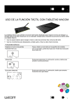
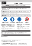
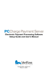
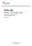
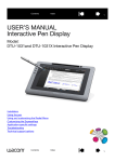
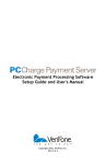
Liberator™
Credit Card System
User Manual
Ver 4.1
©2009 GinSan Industries
Security Notice
It is IMPERATIVE that you take steps to safeguard your business and your customers
from fraud! Don’t be a victim of cyber crime! Protect your sensitive data!
You will be storing sensitive merchant information and consumer credit card information on your computer.
Although VeriFone has gone to great lengths to secure PCCharge™, it is the merchant’s responsibility to
secure the system on which PCCharge resides and the environment in which it is used. Criminals continuously
find new ways to commit fraud, and therefore it is crucial that you take an ongoing and layered approach to
security. Use multiple tools and protect all areas (your network, individual PCs, laptops, servers, databases,
backup data, etc.) that contain or transmit sensitive data.
At a minimum, VeriFone recommends that you read and implement the following suggestions:
1. If your computer has any kind of Internet connection, install a firewall prior to processing financial
transactions. Even if you already have a firewall, check for new versions to ensure that you have
the most up-to-date firewall available. Follow industry standards for hardening your firewall prior
to processing financial transactions.
2. Hard copy documentation containing sensitive merchant information, such as your Merchant ID (MID) and
Terminal ID (TID), should be safeguarded.
3. Keep software up to date, including Operating Systems (ex. Windows®), Email Programs
(ex. Outlook), and Internet Browsers (ex. Internet Explorer). You can download Microsoft security
updates and patches by visiting www.microsoft.com.
4. Control access to your computer equipment during open and closed hours.
5. If a remote user accesses your computer through a program such as pcAnywhere™, take
measures to lock the program down (see pcAnywhere Manual). You must set up user names
and passwords or change the settings to allow for Windows-based security. You should also
disable the default users “Guest” and “Anonymous”.
6. For more information related to security, visit the following sites.
http://usa.visa.com/business/merchants/cisp_index.html
http://www.sans.org/resources
http://www.microsoft.com/security/default.asp
Document version 5.7.1 – last updated 7/26/2005
Copyright VeriFone, Inc. 2005
PCCharge Security Notice
Warranty Policy
ExpressKey, GinSan, IVS, & Trusco Group of Companies (Company) provides a limited one year warranty on
components and piece of equipment produced by the Company to be free from defects in material and
workmanship. Electrical assemblies see Appendix A, have a limited two year warranty on the controller to be
free from defects in material and workmanship. This limited warranty does not cover equipment that has been
damaged due to misuse, misapplication, modification, altered, neglected, attempted theft, vandalism,
connection to improper voltage supply, modification, or such parts that are commonly recognized to be subject
to wear in normal usage. Normal use products are, but not limited to, those listed on Appendix B; which are
warranted for 90 days. Every component and piece of equipment is packaged to assist in safe handling of the
product.
Claims must be submitted in writing within the appropriate coverage period as covered by this warranty, from
date of shipment, to the Company’s warranty/repair department. If the return is approved an RMA and labeling
instructions will be issued and the product can be returned. Returned product without the appropriate RMA and
label will be issued to scrap and all warranties/replacements will be considered null and void. A testing fee of
$15.00 will be applied, if the product passes all tests related to the written claim, then the fee will be applied and
paid prior to return of the product. If the product fails the test then the fee will not be applied. The Company
may charge a 20% restocking fee for returned product and/or an order, which is canceled, and material has
already been ordered and/or received to fill such order.
The Company’s warranty/repair department will inspect all components, submitted under warranty. Warranty
replacement will be based solely on the analysis and confirmation that the product defect was caused by
material and/or workmanship. The company reserves the right to change the design of the product without
assuming any obligation to modify any product previously manufactured or to replace warranted product other
than with redesigned product.
In some cases it is easier for the customer to send a Company purchased product direct to the manufacturer for
replacement. In those cases the customer will be notified that their product falls under that process and should
work with that manufacturer directly. Appendix C shows the purchased parts that falls under this case.
This warranty covers the product replacement only; charges for damages, freight and/or labor will not be
accepted. There are no warranties expressed or implied which extend beyond this Limited Warranty. The loss
of use of the product, loss of time, inconvenience, commercial loss, incidental or consequential damages is not
covered. The Company shall not be liable for incidental, special, or consequential damages including without
limitation damages resulting from personal, bodily injury or death or damages to or loss of use of property.
APPENDIX A
2-Year Warranty Controllers
Sensortron
Multitron
Touchtron
Timers
Liberator
APPENDIX B
90-Day Warranty Components
Pressure Hoses
Swivels
Nozzles
Seals
O-Rings
Shop Vac
Safety Shut-off Guns
APPENDIX C
Purchased Products that are Handled Direct with the Manufacturer
Shop Vac
Bill Acceptors
PcCharge Software
Introduction and System Operation
Congratulations on your purchase of the GinSan Liberator© Credit Card System, the most versatile credit card
system available for your car wash.
The Liberator© System does not replace your timer. It works in conjunction with your timer in much the same
way as a coin acceptor or bill acceptor. When a card is accepted the Credit Card Device Control (CCDC) will
pulse the timer according to how you have configured the CCDC to operate.
You can configure the CCDC to operate in one of two ways, Running Charge with Stop or Charge per Swipe
using the Liberator© Credit Card Device control software.
In the “Running Charge with Stop” mode you configure your CCDC to give the timer the number of pulses it
takes to start if the customer was using cash or coin. When the time runs down to approximately one second left
the CCDC will give the timer another pulse to keep it running. This will continue until the customer either
presses the “End Transaction” button or the amount of the charge reaches the preset maximum charge.
In the “Charge per Swipe” mode, the CCDC is configured to give the timer a pre-determined number of pulses
per swipe. Once the card is approved the customer will have thirty seconds to swipe their card additional times
to increase the amount of time they have purchased. This will then be processed as one transaction. If the
customer swipes their card after the thirty seconds has expired, it will be treated as a new transaction.
To provide maximum flexibility to the Carwash owner the Liberator© Credit Card System employs PCCharge
Payment Server Software as it’s processing software. A list of licensed processors can be found at
http://www.pccharge.com/products/pccharge_certs.asp . You will need to set up a merchant account with one of
the processors before you can use this system. A convenient worksheet for setting up your PCCharge software
can be located at http://www.verifone.com/PDF/ActivationWorksheet.pdf
For security reasons, GinSan Industries cannot provide technical assistance with your PCCharge
Payment Server software. For technical assistance please contact Verifone at (877) 659-8981.
Please review any applicable Federal, State and local laws relating to the acceptance of Electronic
Payments before activating this or any other Electronic Payments system. The Liberator must be used
in compliance with all Federal, State and Local requirements.
PCI Compliance:
As of June 2008, PCCharge Version 5.7.1 SP8 ships with your liberator system. This
version is PCI certified and compliant. The Liberator software reads the card data and
passes it directly to the PCCharge software, no card data is retained by the Liberator
software. For more information on PCI compliance go to:
https://www.pcisecuritystandards.org
Parts and Tools:
Provided:
a)
b)
c)
d)
Credit Card Device Control (CCDC) – one per access point
Liberator Credit Card Device Control Software (CCS)
PCCharge Payment Server Software
User Manual
Not provided:
a) Shielded CAT5 cable
b) RJ45 connectors for shielded CAT5 cable
c) Broadband router (must provide DHCP server function)
a. Linksys model BEF1SR4
b. Or compatible device
d) Multiport Ethernet switch (necessary if you will be using 4 or more CCDCs)
a. Linksys model SD216
b. Or compatible device
e) Windows PC
Windows Vista Business Edition (32-bit), XP Professional, 2000,
• 512MB minimum of RAM, 1GB preferred
• 125 MB of available hard-disk space, 1GB preferred
• A high speed Internet connection (strongly suggested) OR a Hayes compatible
modem (capable of 56K or more) and an analog phone line
• CD-ROM drive
• 1.2 GHz or higher processor
• Latest Microsoft service pack updates installed
• Merchant Account with a PCCharge-certified processor
• SSL updates if required
• Latest version of Microsoft's Internet Explorer (version 6 or later)
**NOTE: IT IS STRONGLY RECOMMENDED THAT ANY COMPUTER RELATED
DEVICE BE PLUGGED INTO A HIGH QUALITY SURGE SURPPRESSOR OR
UPS.
NOTE: Installation of the Liberator© software and hardware will involve setting up and configuring
computer network devices and making connections to them. If you are unsure of taking on these
activities, you should seek out and retain the services of a local computer networking services provider.
Look in your local telephone book under “Computers” or visit your local computer store such as Best
Buy.
ATTENTION: Do not install the Liberator© software until instructed to do so.
Hardware Installation:
***NOTE*** Shielded CAT5 cable is required. This is not provided.
Run your shielded CAT5 cable from your access point (i.e. bay, vacuum, etc) back to the location in your
equipment room where the PC will be placed. These must be direct runs. They cannot be a daisy chain
configuration. Terminate the cable(s) in the equipment room with a male RJ45 connector. The cables should be
wired as a direct connection, NO CROSSOVER. You will want to label what access points these cables came
from (i.e. Bay 1, Vac 4, etc.)
DO NOT PLUG THESE IN UNTIL INSTRUCTED.
For some helpful tips on installing CAT5 cable see Appendix E in the back of this manual.
Terminate the shielded CAT5 cable using the connector provided on the Ethernet cable extending out from the
CCDC.
Unscrew the black end from the round 4 pin circular connector on the CAT5 cable from the CCDC to reveal the
insulation displacement connection points. Connect your CAT5 wires as follows:
Pin 1 on RJ45 to Brown on circular connector
Pin 2 on RJ45 to Black on circular connector
Pin 3 on RJ45 to Blue on circular connector
Pin 6 on RJ45 to White on circular connector
RJ45 Jack and Plug Pinout
NOTE: Pins 1 & 2 and 3 & 6 need to be twisted pairs
1. Remove the conductor sheath to
approximately 1.5”
2. Slide into the connector as far as it
will go.
3. Snap the wires into the marked
entry points
4. Cut off the projecting wire so that
there is no overhang.
5. Push the union nut onto the contact
carrier and tighten.
Wire the CCDC into your equipment using the wiring diagram provide is Fig 3:
Fig 3:
**Note: If you purchased your equipment prewired from the factory this step will not be necessary.
When power is properly applied to the CCDC, a red LED on the circuit board will be illuminated and slowly
flashing and a green led will be on steady. The CCDC will be displaying “Credit Card Not Available”
F) Computer setup
**NOTE: You must have the following for the system to operate properly:
• PC with Windows Vista Business Edition (32-bit), Windows XP Professional,
2000, or 2003
• 512 MB minimum of RAM, 1GB preferred
• 125MB of available hard-disk space, 1GB preferred
• A high speed Internet connection (strongly suggested) OR a Hayes compatible
modem (capable of 56K or more) and an analog phone line(A dialup connection may
take 60 seconds or longer to obtain an authorization.)
• CD-ROM drive
• 1.2GHz or higher processor
• Latest Microsoft service pack updates installed
• Merchant Account with a PCCharge-certified processor
• SSL updates if required
• Latest version of Microsoft's Internet Explorer (version 6 or later)
• Latest DotNet Framework updates
**NOTE: IT IS STRONGLY RECOMMENDED THAT ANY COMPUTER RELATED DEVICE BE PLUGGED
INTO A HIGH QUALITY SURGE SURPPRESSOR OR UPS.
Section 1: Hardware and software installation:
****NOTE: Due to the limitations of consumer grade Ethernet devices,
for CAT5 cable runs in excess of 130 feet the installer/owner should
consult with a computer networking professional for assistance in
planning and/or installing the Ethernet network for the Liberator.
If your Liberator will need to co-exist with other wash control systems, such as a PDQ Laserash, please
refer to the diagram in Appendix D page 23.
Install your broadband router per manufacturer’s instructions. You may need an active internet connection to
initialize this device. This router must provide DHCP server function.
Most broadband routers only come equipped with 4 available ports. If you will be connecting more than 3
CCDCs to this system you will need to use a Multiport Ethernet switch (not provided). The switch must be
installed between the CCDCs and the router (Fig 4)
Figure 4
To Internet
Modem
Router
WAN
Computer
LAN
Switch
CCDC
CCDC
CCDC
CCDC
CCDC
CCDC
CCDC
CCDC
CCDC
CCDC
*NOTE: The router must provide the DHCP function
**NOTE: The switch is optional and only used in instances where you
have more devices to connect than available ports on your router.
Install and configure your PCCharge Payment Server software per manual. You MUST have your merchant
service account established and active. For a list of PCCharge licensed processors go to:
http://www.verifone.com/PDF/ActivationWorksheet.pdf
NOTE: This software takes some time to load, both at install and when starting the program. Please be
patient.
NOTE: During the installation you may be prompted by a window entitled “User Account Control”. This
is a new Vista feature that helps to maintain the integrity of your operating system. If this window
appears, select “Continue” and proceed with the installation process.
PCCharge Payment Server Setup Requirements:
- Must be installed to the default directory
- Must be configured with ONLY ONE user
- Must be configured with ONLY ONE card processor
- Must be configured to “use default card processor” and Merchant ID
NOTE: For security reasons, GinSan Industries does not provide technical support for PCCharge
software. For technical support please contact VeriFone at (877) 659-8981. For questions related to your
merchant account and PCCharge software please contact your merchant service account provider.
Place the CD labeled Liberator Control Software in your CD drive. The CD will autorun. If it does not, browse to
your CD drive and double left click on the GinSanSetup.exe file.
Follow the onscreen prompts.
Click
Please read carefully before clicking
Please read the License Agreement, Choose
, and then click
Highlight “Program Files\GinSan\” and delete. Click
.
This will ensure that the software is installed in the proper directory.
Click
to begin installation.
The software will now be installed.
Click on
to end the installation session.
Section 2 Software setup and system operation
***NOTE*** IT IS IMPORTANT THAT YOUR COMPUTER POWER MANAGEMENT PROPERTIES ARE SET
SO THAT THE HARD DRIVE AND OPERATING SYSTEM ARE SET TO NEVER SHUT DOWN, HIBERNATE
OR SLEEP.
To access your power management settings in Windows XP or 2000:
a) Right click on an open space on your desktop and choose “Properties”
b) Click on the “Screen Saver” tab
c) Click on
button on the lower right corner of the window and set all your
settings to “Never”. Be sure to apply your settings.
Click “Ok”
Double click on the Liberator software icon or your desktop:
Create a master password. This must be 6 to 10 characters in length.
**Note: Password is case sensitive. It is recommended that you document your passwords
and keep them in a secure location. PCI Standards Compliance has specific requirements
regarding passwords and software access. Review these requirements to ensure your
compliance at:
https://www.pcisecuritystandards.org
Re-enter password to confirm and select
You will need to enter your “Maximum 24 hour Max Charge” This is the maximum that can be
charged to one card over 24 hours. Click
when finished.
An operator password can be created to allow limited access to the system. An operator
password will allow someone to view, but not change, settings. It will also not allow access to
any reports. If you do not wish to set an operator password at this time, skip this section.
If desired, once setup the Liberator software will operate without anyone being logged into
the system.
Select
Enter operator password. This must be 4 to 10 characters in length and is case sensitive.
Re-enter password to confirm. Select
If you wish to create more operator passwords select
If you wish to enter to the main system select
You are now able to start setting up your devices.
Plug in the cable from your first CCDC into the router (or switch if present)
The software should automatically recognize your device and display a box indicating such.
This box will be yellow until your device is setup.
Now you need to define how the CCDC is going to operate. Select
Select
to label your device. The label is the location that the particular CCDC is
installed (i.e. Bay 1, Vacuum 5, etc).
Next you need to decide how you want your system to charge customers. You have two options:
If you choose this option, when the customer swipes their card, the system will preauthorize the Maximum
Charge per session and then pulse the timer the correct amount of pulses to start. The amount of coins and
time per coin must match your timer**. As the time counts down and nears shutoff, the CCDC will continue to
pulse the timer to keep it running until one of two actions occur: the customer selects the “End Transaction”
button or the maximum running charge is reached.
**Note: In the event your Liberator credit card system is set up for running charge and you have customers
using it for prolonged periods of time you may experience a timing tolerance issue where the timer times out
before the Liberator gives the next pulse to keep going. If you are experiencing this problem the solution is very
simple. Set the Liberator time cycle for 1 second less than the timer cycle. If the timer is set for 8 coins for 4
minutes, set the Liberator for 8 coins for 3 minutes 59 seconds.
The customer will still receive full value as the timer controls the bay or vacuum, not the CCDC
If you choose this option the customer will be charged a set price for each swipe of their card. For example, if
the customer swipes their card the CCDC will charge the card $5 for each swipe and pulse the timer 20 times.
With this option, after the card is authorized, the customer will have 30 seconds to re-swipe their card one or
more times to add addition time. This will be processed as one transaction.
Now you need to select how your system timer works.
Used in most bays and standard vacuums. The customer needs to deposit a certain amount of money to start
up the timer. Time is given on a per coin basis.
Multi price:
This option is used in combination vacuums and requires the use of a multi price timer.
After choosing how your bay or vacuum timer works, you need to define your pricing.
:
Start up Charge – This is how much a customer would have to deposit to start your timer if they were using
cash. You can set this to be higher but your time per coin must the time per coin of your timer
Minutes to Start – This is how much time the customer would receive when starting the timer using cash. This
can be set higher but your time per coin must match the time per coin of your timer.
Charge per minute – This is automatically calculated by the software.
Maximum charge per session – This is the maximum charge that can be applied to a card at one time. This is
for those situations where a customer swipes their card, washes their vehicle, and forgets to push the “End
Transaction” button when finished.
Running Charge with Stop (Multi price timer):
Select the first function.
Set your Start up Charge
Set your Minutes to Start
Repeat for each additional function
When finished, verify your selections
Charge per swipe:
If this is the option you choose, all you will need to enter is your charge per swipe.
**Note: If you have your system set up as a “Charge per swipe” the customer will have a 30 second window to
swipe their card to add more time and still have it count as one transaction.
When you complete the setup of your device, select
The function box will flash red signifying the settings have been transferred to the CCDC and the box will turn
white.
Once the device is properly setup the CCDC will display “Please Swipe Card”
Repeat the above steps for each CCDC. ONLY PLUG IN AND CONFIGURE ONE CCDC AT A TIME.
When completed, each CCDC will be shown in its own block on the main screen of the interface software.
These blocks will be have one of four backgrounds:
White: Communicating – No charge
Teal: Communicating- Authorizing
Green: Communicating – Running Charge
Red: No Communication
If you wish to delete a device, click on the “Details” button for the selected device.
Disconnect the CCDC you wish to delete and select the
You will receive a confirmation screen:
Select
to delete the device.
button:
Section 3: CCDC Operation
While at idle the CCDC will display “Please Swipe Card”
When a customer swipes their card the CCDC will read the their name from the card and display a personalized
greeting “Welcome John Smith”
The next thing the customer will see is “Authorizing”. This is displayed for 2 seconds and then alternate with
“One Moment”
If the card is authorized the CCDC will display “Authorized” for 2 seconds.
**Note: If you have your system set up as a “Charge per swipe” the customer will have a 30 second window
after the display reads “Authorized” to swipe their card to add more time and still have it count as one
transaction. At the end of 30 seconds the CCDC will display “Final Charge $XX.XX”
If the card is not read, for any reason, the CCDC will display “Card Read Error” for 1½ seconds and then return
to displaying “Please Swipe Card”
If the card is not authorized, the CCDC will display “Authorization Failed”.
After 2 seconds the CCDC will alternate every 1½ seconds between “Press Cancel to End” and “Accumulated
charge, $XX.XX”.
When the customer is finished and pushes the “End Transaction” button, the CCDC will display “Final Charge.
$XX.XX” for 5 seconds before returning to it’s idle message of “Please Swipe Card”.
Troubleshooting
Symptoms
“Card Read Error”
No Communication
“Authorization Failed”
Bay shuts off and cc still running
Display blank
Issue
The head on the reader is dirty
Resolution
Clean head of reader – The manufacturer
recommends that the reader be cleaned
weekly using a card reader cleaning card or
soft cloth with rubbing alcohol.
Contact GinSan Technical Support
Reader has failed
1-800-446-7267
Contact GinSan Technical Support
Loose connections on 8 pin plug.
1-800-446-7267
Inspect and repair all connections on
Wiring is bad
shielded CAT5 cable
Make sure network is setup properly
See Fig 4
PCCharge Payment Server is not running Start PCCharge Payment Server
PCCharge cannot access internet
Check internet connection
Bad credit card
Use different card
24 hour maximum charge reached
Use different card or wait 24 hours
Set your startup time to 1 or 2 seconds
Timing issue between CCDC and timer
less than the start up time of your timer
Check connections on red and purple
No power to CCDC
wires. You should have 22- 30 VAC
accross these two wires
Contact GinSan Technical Support
Display bad/damaged
1-800-446-7267
Appendix D
Ginsan Liberator CCDC Network Layout With PDQ Laser Wash Equipment
Host Computer
Typically
IP Address - 192.168.55.100
Subnet - 255.255.255.0
NOTES:
1) This is a basic network scheme. Wiring
and connections are site installation
dependent and can and will change
according to the particular installation.
2) The need for additional router or switch
devices is dependent on the number of
CCDC's being installed and the number of
open ports on the 3Com router typically
provided by PDQ.
3Com Router
Modem
Usually -
Follow ISP Provider's instructions.
Each installation will be different.
and is dependent on the particular ISP
IP Address - 192.168.55.99
Subnet - 255.255.255.0
VPN Range - 192.168.55.50 to 192.168.55.60
DHCP Range - 192.168.55.30 to 192.168.55.40
3) If installing more than 10 CCDC's, the
DHCP Pool range can be expanded to
utilize unused IP addresses. However, it is
recommended that the range be between
192.168.55.22 and 192.168.55.48.
DHCP Server must be enabled
PDQ Laser Washes
Additional Router or Switch
Usually -
(As Needed)
IP Address 192.168.55.101 to 192.168.55.255
Set IP Address to an unused IP between
192.168.55.90 and 192.168.55.98
DHCP Server - Disable
DNS Relay - Disable
PDQ Nodes
Usually -
CCDC(s)
If there is an open
LAN port on the
3Com Router, a
CCDC can be
plugged into it.
IP Address 192.168.55.1 to 192.168.55.20
ATTENTION -CCDC
This installation involves TCP/IP network scheme layout and configuration. If you are not
confident in your qualifications to perform these functions, it is recommended you consult
and obtain the services of a computer networking professional before beginning.
Appendix E Installing Cat5
Cat 5 cable requires careful and precise installation to maximize efficiency and system performance. Anything that
kinks the cable or disturbs the precise alignment of the wire pairs inside the cable has the potential to create future
performance problems. The following installation practices can help minimize such problems.
Handle carefully. To avoid stressing conductors, limit pulling tension to 25 pounds or less as specified by the
EIA/TIA-568-A standard. In addition, pull cables gradually and with constant tension, taking care not to crush or pinch
bundles.
Be particularly careful when pulling cables around corners, watching out for nails and sharp edges that could damage
the insulation.
When cable lubricant is used, read instructions to be sure it is compatible with the cable's jacket material (PVC
or FEP).
Do not step on Cat 5 cable during installation.
Support carefully. If cable supports crush or compress Category 5 cable, the conductor pairs inside stand a good
chance of being damaged. To avoid this:
Use plastic stand-off cable staples rather than metal cable staples or staple guns.
Apply cable ties loosely, with random spacing. Don't overtighten ties or install them at regular intervals.
Support horizontal cable bundles using broad supports like J-hooks or cable trays. Avoid using narrow "bridle rings"
since they tend to crush the delicate cables.
Terminate carefully. Improper terminations are another leading cause of Category 5 performance problems. For
proper termination, use the proper punch down tool for the connector involved-either 110 or 66 style-and untwist the
wire pairs no more than 1/2 inch to avoid crosstalk (unwanted signals that appear in one wire pair as a result of
inductive coupling from other pairs).
Remove as little of the outer cable jacket as possible; the rule of thumb is 3 inches.
Match wire color codes at all connector blocks, outlets, and other hardware.
More Tips:
Besides taking care with the cable, its supports, and termination procedures, following these do's and don'ts can help
assure proper installation of Cat 5 cabling:
Do keep cable length from telecom closet to outlet (jack) to within 295 feet (90 meters).
Don't splice or repair damaged cables between the telecom closet and outlet locations. Instead, pull a new cable if
there's a problem. To minimize induced interference, don't allow Category 5 cables to cross power cables at right
angles. Likewise, don't run telecommunications cabling in the same conduit or through the same metal stud opening
as power wiring.
Do follow the grounding and bonding requirements established by the Electrical Code, TIA standard 607, and
equipment manufacturer specifications. Proper grounding and bonding not only protects personnel and equipment
from hazardous voltages, but also reduce the effects of electromagnetic interference (EMI) to and from the
telecommunications network.
Don't lay data cables directly across ceiling tiles, grids, or fixtures. Use cable tray or other methods to support the
cables and keep them at least 6 inches away from fluorescent or HID light fixtures.
Don't bend Category 5 cable more tightly than eight times the cable diameter (a 2-inch bend radius).
Do keep installations as neat as possible and document connections carefully.This pays off later by
simplifying system administration and maintenance.