1
server (ssee the confiiguration filee in Appendiix A) or by using
u
the YaaST [37] whiich is a conffiguration
and instaalling tool foor the openSU
USE [29] sysstem.
To vverify that thhe DHCP server workss we used Wireshark
W
(See section 33.1.1) to mo
onitor the
network traffic; thuus we could verify thhat the expeected DHCP
P discover, offer, requ
uest, and
acknowlledge messagges were excchanged and that the mottherboard recceived the IPP address thaat we had
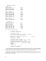
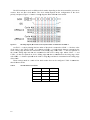
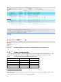
configurred for it. Figure
F
3-4 shows
s
a scrreen capturee of the DH
HCP handshhake as cap
ptured by
Wiresharrk. Note thhat the DHC
CP server w
was running
g on a com
mputer withh the IP ad
ddress of
192.168..1.100.
Figure 3-44:
A scree
en capture of th
he DHCP proce ss
3.4.2 C
Configuring
g the TFTP server
As m
mentioned beefore a TFTP
P server simpplifies the loaading of a neew applicatioon into the board.
b
For
this purppose we set up a TFTP server.
s
We ddecided to seet up the TF
FTP server oon the same computer
that wass acting as the
t DHCP server.
s
The TFTP server was also configured
c
tthrough YaS
ST in the
openSUS
SE PC deksttop. By usin
ng Wiresharkk on the worrkstation thatt was hostingg both the TFTP
T
and
DHCP seerver, we veerified that th
he TFTP servver worked by
b transferrin
ng files betw
ween two PC``s (one of
which w
was the TFTP
P server).
Wheen connectingg the motherrboard to thee network, th
he motherboaard should innitially makee a DHCP
request aand then dow
wnload the configured
c
aapplication from
fr
the TFT
TP server. H
However in our
o initial
experimeents this did not happen faultlessly.
f
T
This is also laater explaineed in section 4.3.
3.5 S
Serial Pe
eriphera
al Interfface (SP
PI)
SPI is a data linnk which caan operate inn full or hallf duplex mo
ode. This innterface is co
ommonly
implemeented by microprocesso
m
ors. Using eeither a 4-w
wire (or 3-wire) conneection SPI allows a
microproocessor (miccrocontrollerr) to comm
municate witth other dev
vices such as sensors or other
microproocessors thatt support SPII.
The SPI protocool is designed
d to support a single masster device to communiccate with onee or more
slaves cconnected too a serial bus. The maaster (the microprocesso
m
or) initiates communicaation and
providess a clock forr synchronization. The sslave is a device (in our case either a NFC-read
der or the
ENC28JJ60 Ethernet controller) which
w
responnds to the maater’s commu
unication, recceives comm
mands and
sends daata, under thee control of the micropro
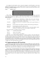
rocessor. Tab
ble 1 shows the signals uused by SPI.. We will
use thesee names for these
t
signalss in our descrription*. SPI utilizes 8 bitt bytes [38].
Table 1:
SPI sign
nals
Signal Nam
me
SCLK
MOSI/SIM
MO
MISO/SOM
MI
SS (CE)
*
Description
Serial
S
Clock
Master
M
Outpuut Slave Inpu
ut
Master
M
Input Slave Outpu
ut
Slave
S
Select ((Chip Enablee)
Note thaat there are othher commonly
y used names for these sign
nals.
14