1
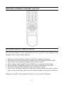
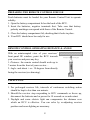
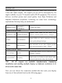
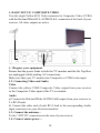
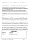
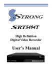
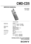
HHT894 USER’S MANUAL CONTENTS CONTENTS ................................................................................................... 2 PREFACE AND FEATURES ....................................................................... 3 FEATURES INCLUDE ................................................................................. 3 SAFETY ......................................................................................................... 4 GENERAL OPERATION OF THE RECEIVER ......................................... 4 FRONT PANEL ............................................................................................. 5 REAR PANEL ............................................................................................... 5 REMOTE CONTROL UNIT KEY LAYOUT .............................................. 6 BATTERY SAFETY PRECAUTIONS ........................................................ 6 REMOTE CONTROL UNIT KEY FUNCTIONS........................................ 7 PREPARING THE REMOTE CONTROL FOR USE ................................. 8 REMOTE CONTROL OPERATING DISTANCE & ANGLE ................... 8 USEFUL TIPS................................................................................................ 8 SETING UP ................................................................................................... 9 GETTING STARTED .................................................................................. 14 INITIAL AUTO SCAN ............................................................................... 14 SCAN ........................................................................................................... 15 ¾ AUTO SCAN .................................................................................. 15 ¾ MANUAL SCAN ........................................................................... 16 SETTINGS ................................................................................................... 17 EDIT CHANNELS ...................................................................................... 19 SYSTEM INFORMATION ....................................................................... 21 OTHER FEATURES ................................................................................... 21 EXTENDED INFORMATION – NOW&NEXT ........................................ 22 7-DAY ELECTRONIC PROGRAM GUIDE.............................................. 23 AUDIO MODE SELECTION ..................................................................... 24 TROUBLESHOOTING ............................................................................... 25 SPECIFICATIONS ...................................................................................... 26 CHANNEL FREQUENCY TABLE ........................................................... 27 12-MONTH WARRANTY ......................................................................... 29 2 PREFACE AND FEATURES Thank you for choosing a healing HHT894 High Definition Receiver. HHT894 is easy to install with all AV outputs active simultaneously. Built in a small footprint case less than 220mm wide with a removable mains power lead, HHT894 includes full 7 day Electronic Program Guides. Optical Digital Audio can provide full surround sound. Closed Caption Subtitle and Teletext functions are embedded in the receiver. Equipped with a proven SGS Thomson main chip, healing HHT894 delivers beautiful High Definition and Standard Definition Television pictures. FEATURES INCLUDE 1. Resolutions: 1920 x 1080i, 1280 x 720p, 720 x 576p and 720 x 576i 2. HDMI, Component Y/Pb/Pr and Composite CVBS Video outputs 3. 7 day Electronic Program Guide (EPG) with 8th day cross over 4. Full Closed Caption and Teletext functions embedded 5. Automatically updates broadcaster program changes 6. Centre Cut option displays 16/9 on 4/3 screens 7. Signal Strength and Quality bars colour coded 8. Stores up to 360 TV and Radio channels 9. Saves program parameters at Power Fail 10. All Video outputs active simultaneously 11. Compact case less than 220mm wide 12. Optical Digital Audio SP/DIF output 13. Outstanding HD picture quality 14. Our most sensitive tuner yet 3 SAFETY 1. 2. 3. 4. 5. 6. 7. Allow clear space around the receiver to provide sufficient ventilation Do not cover the receiver’s ventilation slots or place it near a heat source Use a soft cloth and mild washing solution to clean the case Do not connect or change cables when the receiver is-plugged in Do not remove the cover Do not allow the unit to be exposed to extreme heat, cold or humidity Liquids, sprays or other materials must not make contact with internal parts GENERAL OPERATION OF THE RECEIVER The everyday operation of your receiver is accessed via user friendly On Screen Displays and Menus. These Menus can guide you through installation and channel manager with its various functions to enhance your viewing pleasure. All functions can be accessed through the Remote Control and the front panel keys provide access to many functions. As new software may change the function of a receiver it should not be installed unless specific upgrade instructions have been given by healing for this receiver. Should you experience any difficulties with the operation of your unit, please consult the relevant section of this manual or Trouble Shooting. Alternatively call your dealer or healing via www.healingdigital.com 4 FRONT PANEL 1 2 3 4 1. STANDBY key - Switches between Operational and Standby modes. 2. Numerical LED display - Shows channel selected, Load status etc. Power LED, green - Indicates power supply active. Signal Lock LED, orange - No Light = No Signal = No Pictures and Sound. 3. CH+ key. Use to turn channel upwards. 4. CH- key. Use to turn channel downwards. REAR PANEL 1. ANT IN: Connect to your external aerial, essential for stable pictures. 2. LOOP OUT: Antenna RF output, for another receiver or 75Ω terminator. Loop Out becomes idle when receiver on STANDBY 3. AUDIO OPT DIG: Audio Optical Digital output, 1 x Toslink. 4. RS 232: for software upgrade, 1 x DB9. 5. HDMI: Combined digital video and audio output. 6. CVBS: composite video signal output, 1 x RCA. 7. AUDIO L: signal outputs, 1 x RCA. 8. AUDIO R: signal outputs, 1 x RCA. 9. Component Video: Y/Pb/Pr outputs, 3 x RCA. 10. Mains power connection : IEC C7 figure 8. 5 REMOTE CONTROL UNIT KEY LAYOUT BATTERY SAFETY PRECAUTIONS The following Battery Safety precautions can save your RCU from damage from improper use of or poor quality batteries. 1. 2. 3. 4. 5. 6. 7. Double check that polarities of battery and RCU terminals correspond. If storing your receiver for weeks or longer, remove the batteries from the RCU. Never leave old or exhausted batteries in the remote control. Only recharge cells designed for this (NiMh etc.) on a purpose built charger. Do not attempt to disassemble, short-circuit, heat or throw batteries into fire. Do not mix new and old or different types of batteries together. In the event electrolyte fluid does leak from a battery inside the remote control, wipe it away with a damp cloth, rinse the cloth thoroughly and insert new batteries. Damage to your RCU from leaking electrolyte is not covered by Warranty. 6 REMOTE CONTROL UNIT KEY FUNCTIONS ¾ ¾ ¾ ¾ ¾ ¾ ¾ ¾ ¾ ¾ ¾ ¾ ¾ ¾ ¾ ¾ ¾ ¾ ¾ STANDBY. Switch between Standby and Operational. MENU. Show Main Menu. MUTE. Mute audio FAV. Shows Favorite channel list. VOL+/-. Controls Audio levels. TV/R. Switch between Television and Radio programs. EPG. Show [Electronic Program Guide]. Select channels by numbers LIST. Shows Service List containing all channels scanned INFO. Shows general information for the current program on the channel selected. OK. Confirm selected Menu item EXIT. Exit the current Menu function UP/DOWN. In “Menu Mode”: moves Cursor Up or down; “Non-Menu Mode”: moves Program Up or Down. LEFT/RIGHT. In “Menu Mode”: moves cursor Left or Right; “Non-Menu Mode”: Audio Volume Up or Down. TTX. Activates Teletext (where broadcast) Blue key: Closed Captions on or off. Green: Freeze picture, press again to release. ASPECT. Steps through 3 Aspect Ratio options. AUDIO. Displays AUDIO CTL Menu options. 7 PREPARING THE REMOTE CONTROL FOR USE Fresh batteries must be loaded for your Remote Control Unit to operate reliably. 1. Open the battery compartment lid on the back of the RCU. 2. Insert the batteries, negative terminals first. Take care that battery polarity markings correspond with those of the Remote Control. 3. Close the battery compartment lid, checking that it locks in place. 4. Your RCU should now be ready for use. REMOTE CONTROL OPERATING DISTANCE & ANGLE With an uninterrupted view of your receivers’ front panel IR window, point the RCU towards your receiver and press any key. 1. Distance: the remote control should work up to 7 meters from the front of your receiver… 2. Angle: and about + or - 30 degrees from directly facing the receiver (see drawing). USEFUL TIPS 1. For prolonged receiver life, intervals of continuous switching action should be kept to less than one minute. 2. Should the receiver stop responding to RCU commands or freeze up, disconnect the batteries and or power for 10 seconds or so and restart. 3. Daylight and some electric light can compromise the distance over which an RCU is effective. You can solve by re-adjusting receiver position and room lighting as necessary. 8 SETING UP Your healing HHT894 High Definition Receiver comes with a selection of Video and Audio outputs. The outputs you use will be determined by the inputs available on your TV monitor and/or HI-FI equipment. This receiver delivers excellent picture and sound quality from High Definition and Standard Definition broadcasts. Following are some basic terminology explanations that may help you understand: QUALITY TERMINOLOGY GRADING EXPLANATION VIDEO CONNECTIONS Complete video signal on one yellow RCA Composite CVBS Standard Definition Y/Pb/Pr High Definition connector. Ideal for smaller screens. Analogue. Separate RGB over 3 RCA connectors. Excellent picture quality although Analogue. Video and Audio on one cable. Highest possible HDMI High Definition picture and sound quality to 1080i. Digital. AUDIO CONNECTIONS RCA analogue Optimal Left and Right channels via RCA connectors in high impedance. Analogue. Optical SPDIF CD quality Digital stream via Toslink for multi channel audio. Surround sound decoder ready, when broadcast. N.B. All AV outputs are available simultaneously, simplifying installation and enabling multiple displays of different resolutions to be driven at the same time. Now you can choose the connection method that best suits your display from one of the methods listed on the following pages: 9 1. BASIC SET UP- COMPOSITE VIDEO Uses the single Yellow RCA Video connector for Composite Video (CVBS) with the Red and White RCA AUDIO R & L connectors at the back of your receiver. All video outputs are active. 1. 1Prepare your equipment Ensure that the power leads to both the TV monitor and the Set Top Box are unplugged whilst making AV connections. Make sure that your TV monitor has Composite or CVBS video input. 1.2. Connecting Video and Audio Video Connect the yellow CVBS Composite Video output from your receiver to the Composite Video input of the TV or monitor. Audio a) Connect the Red and White AUDIO L&R output from your receiver to 2 x RCA leads. b) Connect the other end of each RCA lead to the corresponding Audio input connectors on your television monitor. 1.3. Connect the antenna… To the “ANT IN” connection on the rear of your receiver. 1.4. Connect mains power… 10 To the back of your receiver using the IEC C7 figure 8 power lead supplied. You are now ready for GETTING STARTED. 2. BASIC SET UP - COMPONENT VIDEO (Green Blue Red) For a basic component connection, use the Red Blue Green video and the Red White audio connectors on the back of the receiver. The RCA leads included with your receiver can assist. All video outputs are active simultaneously. 2.1. Prepare your equipment Ensure that the power leads to both the TV monitor and the Set Top Box are unplugged whilst making AV connections. Your television or monitor must have a Component video input, which may be labeled “Y, Pb, Pr” and characterized by colored Red, Green and Blue connectors grouped together. 2.2. Connecting Video and Audio Video a) Connect one end of a 3 wire RCA lead to the Red, Green and Blue Y, Pb, Pr RCA output connectors on the rear of the set top box. b) Connect the other end of this cable to the corresponding RCA video input connectors on your television or monitor. 11 Audio. c) Connect a 2 wire RCA lead to the Red and White AUDIO L&R output connectors on the rear of the set top box. d) Connect the other end of the cable to corresponding the audio input connectors on your television or monitor. e) Digital Audio for an external decoder is available from the Toslink Audio Optical Digital terminal. Audio c) Connect one end of each of 2 x RCA leads to the Red and White AUDIO L&R output connectors on the rear of the set top box. d) Connect the other end of the cable to corresponding colored input connectors on your television monitor. e) You also can link Digital Audio from the COAXIAL or OPTICAL SPDIF terminal to its corresponding connector on a TV set for a perfect audio. 2.3. Connect the antenna… to the “ANT IN” connection on the back of your receiver. 2.4. Connect mains power… to the back of your receiver using the IEC C7 figure 8 power lead supplied. You are now ready for “GETTING STARTED. 3. BASIC SET UP- HDMI Uses the HDMI connector on the back of the receiver to provide a complete digital video and audio connection in one neat cable. A HDMI cable of length to suit your purpose is required. All video outputs are active. 3.1. Prepare your equipment Ensure the power leads to both display and receiver are unplugged whilst making your AV connections. Your Monitor must have a HDMI input. Check your Monitor has a HDMI input. 3.2. Connect the antenna… to the “ANT IN” socket on the rear of your receiver. 3.3. Connect mains power… to the back of your receiver using the IEC C7 figure 8 power lead supplied. 12 Video and Audio share the one HDMI cable You are now ready for GETTING STARTED. 13 GETTING STARTED 1. 2. 3. 4. 5. 6. Select the most suitable display or TV connection method. Connect a functional TV Antenna to your digital receiver. Turn on your monitor or TV. Turn on your HHT894 receiver. Select the appropriate Input on your monitor or television and connect. The HHT894 Menu should be visible on your Monitor or TV. INITIAL AUTO SCAN ¾ Initial Auto Scan For first time set up (from Factory Default), dialogue box says “No valid program to be played” and asks “start auto search now?” You can press [Yes] or after 10 seconds Auto-Scan will begin automatically. When channels required have been passed, you can press the “EXIT” key to escape. Unplugging the Antenna until the scan approaches desired channels may speed up Auto Scan. Front panel LEDs show centre freq. of channel being scanned. ¾ Main Menu Select Main Menu by pressing the MENU key. Use the UP/DOWN keys to scroll through Menu Items. Press the OK key to activate your selection. 14 SCAN ¾ AUTO SCAN 1. Press the Menu key, the “Main Menu” will show. 2. Use the UP/DOWN keys to scroll to the “Scan” sub-menu. 3. Press the OK key to activate. Default option is “Auto”. 4. Press the UP/DOWN keys to select “Start” and press the OK to commence “Auto Scan”. 5. “Auto Scan” will list services found placing them in the information box. As each service is found information pertaining to that service will display in the information box. 6. On completion the Process bar shows 100% and info box shows the number of channels found. Press the EXIT key to view. 7. When channels required have been scanned you can press the EXIT key to escape. Program Update - Auto HHT894 detects changes to program line ups within channels, rescans and saves the changes automatically. A brief On Screen message confirms this activity when it occurs. This function virtually eliminates the need for Manual Scan. 15 ¾ MANUAL SCAN 1. Select the channel to scan by entering its Centre Frequency in KHz. A list of this data appears on page 27 at the end of this Owner’s Manual. Scanning manually by frequency enables non standard channels to also be tuned. Press Menu key, the “Main Menu” will show. 2. Use the UP/DOWN keys to scroll to “Scan”. 3. Press the OK key to activate “Scan” sub-menu. 4. Press the LEFT/RIGHT keys to select “Manual”. 5. Press the UP/DOWN keys to select “Frequency”. 6. Press LEFT [<.<.<.<.<.<.<…] to clear Frequency data. 7. Enter centre Frequency of channel to scan in “KHz.” 8. Press the UP/DOWN keys to select “Start”. 9. Press OK to commence Manual Scan. 10. Program info. pertaining to the channel scanned will display in the information box at the bottom of the screen. 11. On completion press EXIT to return to the “Main Menu”. NOTE: This receiver stores Secondary transmitter or Translator channels found by assigning a 35* prefix to each channel number. This point is helpful to understand as this sensitive receiver can receive channels not intended for your area. As Secondary transmitters are provided to serve people located in difficult reception areas a Primary transmitter can be a more reliable source of your TV signal where possible. 16 SETTINGS Default Input Pin is 0000 ¾ AV SETTING Screen Ratio. You can set your HHT894 screen shape to match your display or TV. Select 4:3 (normal) or 16:9 (wide) by using the </> keys. 4:3 is the aspect ratio for conventional Analog TV screens; 16:9 for modern wide view screens. Press a </> key to select from available options. Press a UP/DOWN key to highlight “Confirm”, press OK and EXIT keys to complete. Aspect Ratio. Allows adjustment of picture format to fill screen. Includes 4/3 Centre Cut which allows a 16/9 picture to fill a 4/3 screen without distortion or black bars. You can access this function by either the ASPECT Hot Key or the Aspect Ratio menu option in AV SETTING. OUTPUT MODE. From this option you can select from the output modes available from the Output Mode list. ¾ SYSTEM SETTING Parental Lock Options: 1. Parental Guidance settings allow you to block programs at a given rating level and above. Ratings are transmitted by broadcasters for most programming. 2. From the “MAIN MENU” select the “Settings” sub menu and press the OK key. 3. An “Input Pin” dialogue box shows. Enter PIN to access the next sub-menu level. Default Password is 0000. 17 4. Use the UP/DOWN keys on the Remote Control to highlight “System Setting” and press the OK Key. 5. Use the UP/DOWN keys to select “Parental Lock”. 6. Using the </> key make a selection. 7. Press EXIT, EXIT to automatically save your change and to return to “MAIN MENU”. 8. When a program carries a rating equivalent to or greater than the Parental Lock level selected the program will be blocked and the “PIN code” dialogue box will be activated. Enter your PIN code to view the program. Time Zone: Time and Date are sensed automatically from the broadcast stream. Daylight Saving Offset is applied by selecting your State. When your selection is highlighted, press the OK key to confirm your selection. On completion press EXIT, EXIT to return to the “MAIN MENU”. 1. From the “MAIN MENU” select the “Settings” sub menu option and press the OK key. 2. An “Input Pin” dialogue box will display. Enter your PIN to access. 3. Use the UP/DOWN keys to highlight “System Setting” and press OK. 4. “Time Zone” is the first Sub Menu. 5. Use the </> keys to make your selection. 6. Press EXIT, EXIT to leave the sub-menu and save your changes. Changing PIN: WARNING! RECORD YOUR NEW PIN!! 1. You can change your PIN to any four numbers. 2. Default PIN is 0,0,0,0 3. First the current PIN must be entered 18 correctly followed by your new PIN and verification. 4. Press EXIT, EXIT to return to “MAIN MENU”. ¾ Factory Reset: Factory Reset returns the receiver to its default settings. 1. From the “MAIN MENU” select the “Settings” sub menu option and press the OK key. 2. “Input PIN” dialogue box displays. Enter PIN to access the next menu level. 3. Use the UP/DOWN keys on the remote to select “FACTORY RESET” and press the OK key. WARNING: ALL Channels, Favorites, Parental Lock and State selection DATA WILL BE LOST. Receiver will reset to factory default once you confirm. 4. Press the Red key to confirm Factory Reset. On completion press EXIT, EXIT to return to “MAIN MENU”. Receiver advises “NO CHANNEL”. EDIT CHANNELS ¾ EDIT TV AND RADIO CHANNELS The “Edit Channel” Menu allows you to Sort, Delete and Select Favourite Channels. From the “MAIN MENU” select the “Edit Channel” sub menu option and press the OK key. The “EDIT CHANNEL” options will display. Use the UP/DOWN keys to highlight either “Edit TV Channel” or “Edit Radio Channel”, and then press the OK key. Delete 1. Use the UP/DOWN keys on the remote 19 to highlight channels to delete. 2. Press the “Red” key and dialogue box will ask you to confirm. 3. Press OK when “YES” is highlighted to complete channel deletion. *To recover deleted channels you must Re-Scan. Favorites 1. Use the UP/DOWN keys to select channels you wish to make favorites. 2. Press the “Yellow” key to deselect or select channels as favorites. 3. Press the “FAV” key on the remote to access your Favorites List - in normal operational mode. SORT 1. Press the “Blue” key to access the Sort options. 2. Use the UP/DOWN keys to select channels you wish to make favorites. 3. Use the UP/DOWN keys to make your selection and press OK. 4. Press the EXIT key to leave the sub-menu environment and save your changes. 20 SYSTEM INFORMATION This shows the Firmware Version etc. of the receiver. OTHER FEATURES ¾ Closed Captions Closed Captions can be switched on at any time by pressing the Blue key on the Remote Control Unit. Pressing the Blue key again turns Closed Captions Off. ¾ Teletext Your receiver includes a full Teletext service, enhanced to avoid errors. Press the TTX key on the Remote Control Unit to activate. Press EXIT to deactivate. ¾ Video Freeze Activate by pressing the Green key on the Remote Control Unit. Press again to resume normal viewing. 21 EXTENDED INFORMATION – NOW&NEXT ¾ NOW - Press the INFO key on the remote to activate the basic information plate (picture 1). For more detailed information about this program, press the OK key while the basic information plate is displayed (picture 2). ¾ NEXT - Press the INFO key on the remote to activate the basic information plate (picture 1). Press the INFO key again to view NEXT Program info. (picture 3). For detailed NEXT Program information, press the OK key while the basic information plate is displayed (picture 4). (picture 1) (picture 2) (picture 3) (picture 4) 22 7-DAY ELECTRONIC PROGRAM GUIDE 1. A comprehensive Electronic Program Guide (EPG) is transmitted by most broadcasters with details of Program Names, Times and Descriptions that can exceed more than 7 days in advance. (picture 1) 2. You can access the EPG by pressing the EPG key on the Remote Control Unit. (picture 1) 3. Use the UP/DOWN keys to select a channel. Press the OK key once to display today’s program list. Present program is highlighted in Yellow. Press the </> keys to see the program list for another day. Program detail appears on screen in the top right hand frame. The UP/DOWN keys reveal full program description where necessary. (picture 2) 4. Press the Red key to “Order” a reminder of the start of a program. Or to select a different current program from within the EPG. (picture3) 5. Press the Blue “Timer” key to view a summary of your program reminder Orders. Alarm clock icons show to the right of programs with reminders ordered. (picture 4) (picture 1) (picture 2) (picture3) (picture 4) 23 AUDIO MODE SELECTION Using the Audio Control menu: 1. Press the AUDIO key on the remote control, with your receiver in normal mode The AUDIO CONTROL menu displays. 2. Press the UP/DOWN keys to select from TRACK, and OUTPUT. MULAUDIO describes the Audio of the presently tuned channel. Press the OK or “+” keys to engage a Sub Menu. Use the UP/DOWN keys to select an option. 3. The “#” symbol indicates current selection. AUDIO CONTROL extinguishes after 5 seconds or by pressing the “EXIT” key. 24 TROUBLESHOOTING Check your receiver with the suggestions below. PROBLEM SUGGESTION No Power Check the power cord is plugged in - at both ends. No Reception Check operational antenna cable is properly connected. Receiver not responding to the Check Remote Control batteries and battery contacts. Remote Control Unit. Ensure room lighting is not compromising IR signals. The receiver is not responding Disconnect the receiver’s mains power. Wait about 1 to the remote control or front minute and power the unit up again. You may need to reset to Factory Default and rescan. panel keys. I can see the menu but cannot First check a functional Antenna is properly connected view any channels Then scan for Digital channels available in your area by selecting Main Menu, Scan, Auto and Start. Receiver on but I can’t see Check the required AV or HDMI cables are properly Video or Audio connected – at both ends. After Scanning I cannot see all Your antenna system may need to be updated for Digital of the channels available in my reception by an experienced specialist. area. One or more of my channels This also indicates that your antenna may need “breakup” while viewing. professional attention. The message “No Signal” The signal for this service is too weak to be displayed. displays when a scanned As this is a high sensitivity receiver this also suggests your antenna system needs professional attention. channel is selected. i. No Audio ii. iii. Check the Red and White audio leads from the receiver are properly connected. Check the Mute is not activated on the receiver. Check the receiver’s volume level is high enough. Receiver does not display Allow 30 sec’s to commence. Not all programs include “Closed Captions” or Closed Captions. Teletext is broadcast by 7 network “Teletext” and some regional broadcasters. 25 SPECIFICATIONS ¾ Decodes High Definition and Standard Definition Digital Terrestrial TV & radio. ¾ Video Outputs HDMI, Component Y Pb Pr and Composite CVBS. ¾ Video Resolutions 1920x1080i, 1280x720p, 720x576p or 720x576i. ¾ Aspect Ratios Widescreen 16:9, Centre Cut 4:3 or Letterbox 4:3. ¾ Audio Outputs CD quality Analogue via RCA’s or Digital Optical AC3 via Toslink. With AC3 (5.1), where broadcast. ¾ Audio modes Stereo, Dual Channel, or Mono. ¾ Teletext via integrated software decoder, where broadcast. ¾ Closed Captions via Teletext decoder (page 801). ¾ EPG Information 7 day SI EIT p/f tables (including cross-over). ¾ Memory 4MB Flash RAM; 64MB Double Data Rate RAM. ¾ Main Chip SGS Thomson. ¾ Tuner sensitivity typical -80.6 dBm to -82.5 dBm. ¾ Frequency range VHF & UHF 175 - 820MHz. ¾ Channel bandwidth 7MHz. ¾ Modulation mode COFDM 8K or 2K, automatic detection. ¾ Constellation QPSK, 16QAM or 64QAM. ¾ Guard interval ¼, 1/8, 1/16 or 1/32. ¾ Software upgrade via RS-232 serial port. ¾ IR receiver 38KHz. ¾ Mains Power AC90 - 260Volts @ 50/60Hz. ¾ Power Consumption rated at 15W , typical 12W, .6W standby ¾ Energy Safe Vic. MEPS registration VST0015. ¾ Operating Temperature 0 - 40°C. ¾ Case Dimensions 218mm Wide x 44mm High x 170mm Deep. ¾ Weight <1Kg. ¾ Accessories Included: 1 x Remote Control Unit᷍ 2 x AAA Batteries᷍ 1 x 3 RCA - 3 RCA AV lead 1.5m᷍ 1 x IEC C7 figure 8 mains lead᷍ 1 x Owner’s Manual 26 CHANNEL FREQUENCY TABLE BAND CHANNEL NUMBER REQUENCY in KHz VHF 3 6 177500 184500 191500 198500 205500 212500 219500 226500 529500 536500 543500 550500 557500 564500 571500 578500 585500 592500 599500 606500 613500 620500 627500 634500 641500 648500 655500 662500 7 8 9 9A 10 11 12 UHF 4 28 29 30 31 32 33 34 35 UHF 5 36 37 38 39 40 41 12 43 44 45 46 47 27 669500 676500 683500 690500 697500 704500 711500 718500 725500 732500 739500 746500 753500 760500 767500 774500 781500 788500 795500 802500 809500 816500 48 49 50 51 52 53 54 55 56 57 58 59 60 61 62 63 64 65 66 67 68 69 28 12-MONTH WARRANTY Subject to the conditions stated below, your new healing receiver is warranted to be free from defects in workmanship and materials for twelve months from date of purchase. For the period of warranty healing digital’s obligation includes labour and materials, but excludes neglect, accident, abuse, and transportation to and from service station. No liability will be accepted for any consequential loss or damage arising from any function of the receiver. Healing digital reserves the right to determine at its sole discretion fault cause. In the event of a claim, proof of purchase will be required. This warranty applies to the original purchaser only, and is not transferable. The benefits conferred by this warranty are in addition to rights provided under relevant State or Federal legislation, but exclude any other expressed or implied warranty. healingdigital 42 Brunel Rd Seaford VIC 3198 Australia manual ©2009 www.healingdigital.com 29 HHT894 USER’S MANUAL