1
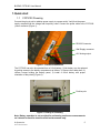
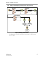
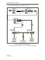
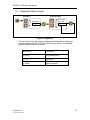
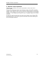
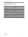
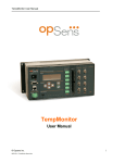
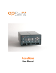
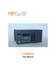
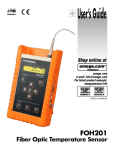
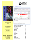
BIOPAC FOTS100 User Manual
FOTS100
User Manual
[email protected]
© Opsens Inc.
IMP0014 PICPW-UM REV2.0
1
BIOPAC FOTS100 User Manual
WARRANTY
All products manufactured by Opsens inc. are warranted to be free of defects in
workmanship and materials for a period of one year from the date of shipment. No other
express warranty is given, and no affirmation of Seller, by words or actions, shall
constitute a warranty. SELLER DISCLAIMS ANY IMPLIED WARRANTIES OF
MERCHANTABILITY OR FITNESS FOR ANY PARTICULAR PURPOSES
WHATSOEVER. If any defect in workmanship or material should develop under
conditions of normal use and service within the warranty period, repairs will be made at
no charge to the original purchaser, upon delivery of the product(s) to the factory,
shipping charges prepaid. If inspection by Opsens or its authorized representative
reveals that the product was damaged by accident, alteration, misuse, abuse, faulty
installation or other causes beyond the control of Opsens, this warranty does not apply.
Service, repairs or disassembly of the product in any manner, performed without specific
factory permission, voids this warranty.
OPSENS MAKES NO WARRANTY OF ANY KIND WITH REGARD TO THIS MANUAL,
INCLUDING, BUT NOT LIMITED TO, THE IMPLIED WARRANTIES OF
MERCHANTABILITY AND FITNESS FOR A PARTICULAR PURPOSE. Opsens shall
not be liable for errors contained herein or for incidental or consequential damages in
connection with the furnishing, performance, or use of this material.
This warranty does not apply to the transducers sold for use with Opsens’ signal
conditioners.
IMPORTANT NOTICE
The product specifications and other information contained in this manual are subject to
change without notice.
Opsens has made a concerted effort to provide complete and current information for the
proper use of the equipment. If there are questions regarding this manual or the proper
use of the equipment, contact BIOPAC inc at:
TEL
FAX
805-685-0066
805-685-0067
WEB SITE
E-MAIL
www.biopac.com
[email protected]
PACKAGING FOR SHIPMENT
If the product must be shipped to a different location or returned to BIOPAC for any
reason through a common carrier it must be properly packaged to minimize risks of
damage.
SOFTWARE LICENSE AGREEMENT
This product contains intellectual property, i.e. software programs, that are licensed for
use by the end user/customer (hereinafter “end user”).
This is not a sale of such intellectual property.
The end user shall not copy, disassemble or reverse compile the software program.
The software programs are provided to the end user “as is” without warranty of any kind,
either express or implied, including, but not limited to, warranties of merchantability and
fitness for a particular purpose. The entire risk of the quality and performance of the
software program is with the end user.
© Opsens Inc.
IMP0014 PICPW-UM REV2.0
2
BIOPAC FOTS100 User Manual
WARNINGS
WARNING: NOT EXPLOSION PROOF!
Installation of this instrument in an area requiring devices rated as
intrinsically safe is not recommended.
WARNING: VOLTAGE SUPPLY!
Use only the wall plug-in power supply delivered with your FOTS100 and
verifies that the input voltage and frequency are compatible with the
power outlet.
© Opsens Inc.
IMP0014 PICPW-UM REV2.0
3
BIOPAC FOTS100 User Manual
Table of content
1.
2.
Table of content
4
Quick start
5
1.1
FOTS100 Powering
1.2
Sensor connection
6
1.3
FOTS100output reading
6
Local Operation
2.1
7
7
2.1.1
Switch on/off
7
2.1.2
Menu Button
7
2.1.3
Left/Right Arrows
7
2.1.4
Up/Down Arrows
7
2.1.5
Confirmation button
7
2.1.6
Log button
7
System Setting
7
2.2
3.
Keyboard
5
2.2.1
Averaging mode
7
2.2.2
Analog output
8
2.2.3
Units
8
2.3
System Diagnostic
2.4
Setting the averaging measurements (Menus levels)
10
2.5
Setting the analog output (Menus levels)
11
2.6
Setting the temperature units (Menus levels)
12
2.7
Diagnostic (Menus levels)
12
Remote control operation
8
12
4. FOTS100 specifications
12
© Opsens Inc.
4
IMP0014 PICPW-UM REV2.0
BIOPAC FOTS100 User Manual
1. Quick start
1.1
FOTS100 Powering
Connect the plug-in wall or tabletop power supply to a power outlet. Verify that the power
supply complies with the voltage and frequency outlet. Connect the power cable to the FOTS100
power connector (Figure 1).
RS-232 Connector
Wall Supply connector
±5V Analog output
Figure 1 : Electrical connectors
The FOTS100 can also be operated from a 9-Volt battery. 9-Volt battery can be replaced
by getting access to the battery compartment as follows: 1) Remove the rubber boot; 2)
remove screws holding the battery panel, 3) install a 9-Volt battery with proper
orientation of the polarity (Figure 2).
Positive pole
Figure 2: Polarity of 9V battery
Note: Battery operation is not provided for performing continuous measurements
so it should be used for short term field measurements only.
© Opsens Inc.
IMP0014 PICPW-UM REV2.0
5
BIOPAC FOTS100 User Manual
1.2
Sensor connection
The FOTS100 is compatible with all TSD180 series Opsens’ GaAs-type of sensors or
transducers for measuring temperature namely the OTG-M series. The fiber-optic connector
provided with the OTG-M sensors is a ST-type connector. Remove the protective cap of the
ST mating and engage the sensor connector with the orientation key properly oriented
(Figure 3). It is a good practice to clean the sensor connector prior to connect it to the
signal conditioner. See the TSD180/TSd181 Fiber-Optic Cleaning Guide for further information on
how to clean fiber-optic connectors.
NOTE: always replace the protective dust cap on the mating when there is no
sensor connected. Always replace the protective dust cap on the sensor fiberoptic connector when not in used
Sensor ST-type fiberoptic connector
ST Mating
Figure 3: Fiber-optic sensor connection
1.3 FOTS100 output readings
Once the fiber-optic sensor is connected, the FOTS100 is ready to measure temperature.
The display shows the temperature measurements with a refreshing rate of three
readings per second. The measurement readings are also available at the analog
output and at the RS-232 port. The refreshing rate of these outputs is equal to the
sampling rate of the conditioner, which is 50 measurements per second.
© Opsens Inc.
IMP0014 PICPW-UM REV2.0
6
BIOPAC FOTS100 User Manual
2. Local Operation
2.1
Keyboard
MENU
2.1.1 Switch on/off
The FOTS100 is switched on/off with this button.
2.1.2 Menu Button
MENU
Menu button gives access to the system menus. Once in the menu, this button
brings the user one level higher into the menu hierarchy. Once at the root, the
system will exit the menu and goes back to measurement display.
2.1.3 Left/Right Arrows
Left/Right arrows allow moving from one digit to the other when a value is
being entered.
2.1.4 Up/Down Arrows
Up/Down arrows allow navigating 1) between menu items of a given
hierarchical level, or 2) it allows changing a value being entered.
2.1.5 Confirmation button
Confirmation button permits confirming 1) a new value being entered, 2)
confirm the selection of a menu item then moving one hierarchical level lower,
3) refreshing displayed value in the case of diagnostic.
2.1.6 Log button
(Reserved for future use)
2.2
System Setting
The functions below are used to setup specific parameters of the FOTS100.
2.2.1 Averaging mode
The user can set ON or OFF the averaging mode (ON by default). When on, the
measurements either displayed on the front panel display, output on the analog output or
on the RS-232 port is the result of the average of twenty sequential measurements
© Opsens Inc.
IMP0014 PICPW-UM REV2.0
7
BIOPAC FOTS100 User Manual
based on the mobile averaging method. So even when averaging takes place, the output
on the analog output is refreshed at a rate given by the sampling rate of the FOTS100.
Note that the front panel display is refreshed a rate of three measurements per second.
The method to set the averaging is described in Figure 4. This parameter is not saved so
the instrument returns to its default state (Averaging ON) after being switched off.
2.2.2 Analog output
The analog output parameters comprise the scale factor and the offset. The scale factor
corresponds to the physical unit per Volt (unit/V) outputted by the system, while the
offset corresponds to the physical value at which the user wants the analog output to be
at zero volt. For example, with a scale factor set to 10 °C / V and the offset set to 5 °C,
the temperature as a function of the analog output voltage is given by:
Temperature = [Voltage output] x 10 °C / V + 5 °C.
The default value of the scale factor is 50 °C / V (or its equivalent in °F) and the default
value of the offset is 0 °C (or its equivalent in °F). NOTE: The analog output during a
NO SIGNAL condition (see section 2.3) is always set to zero volt.
The method to change the analog output parameters is described in Figure 5. Any new
scale factor and offset are saved in the non-volatile memory.
2.2.3 Units
The user can set the temperature units in degree Celsius (default value) or in degree
Fahrenheit. The method to change the units is described in Figure 6.
2.3
System Diagnostic
The user can look through a variety of FOTS100 internal parameter for diagnosing potential
problem with the system as described in Figure 7. The available diagnostics parameters
are shown below. Diagnostic values can be refreshed by depressing confirmation
button .
Parameter and unit values
Description
Lm %
Lamp driving level
Lg Volts
Light level
Sg (no units)
Signal amplitude
The following table shows diagnostic values with good signal, poor signal, or with a
broken sensor (“fault”). A fault condition results in a “No Signal” being displayed.
© Opsens Inc.
IMP0014 PICPW-UM REV2.0
8
BIOPAC FOTS100 User Manual
Parameter
Good signal
Poor Signal
Fault
Lm
< 90 %
> 90 %
—
Lg
> 2.2
< 2.2
—
Sg
> 6 000
< 6 000
< 4 000
NOTE: Without a sensor connected, the instrument shows the message “NoS” or
“No Signal” on its display.
In the unlikely situation that this message appears while a sensor is connected to the
unit, take note of the diagnostic parameters and contact BIOPAC technical support.
During a No Signal condition, the analog output and the serial ports output constant
values as follow:
Output
No Signal condition output value
Analog
0 Volt
RS-232
65 536.0
There are certain circumstances (i.e. when using some remote control programs) where
it is not desirable to have these above constant outputted on serial ports or analog
output. Turning OFF the No Signal functionality will prevent this situation.
© Opsens Inc.
IMP0014 PICPW-UM REV2.0
9
BIOPAC FOTS100 User Manual
2.4
Setting the averaging measurements (Menus levels)
Main Menu
MENU
Average Menu
Setting
Diag.
Average
Analog
Units
Average Setup Menu
Aver. On
Aver.Off
MENU
Selection
Rejected
Selection
Accepted
MENU
Up to data
display
Figure 4: Averaging measurements
•
Averaging: twenty sequential measurements are averaged for obtaining even
smoother signal.
© Opsens Inc.
IMP0014 PICPW-UM REV2.0
10
BIOPAC FOTS100 User Manual
2.5
Setting the analog output (Menus levels)
Analog Menu
Main Menu
Average
Analog
Units
MENU
Setting
Diag.
Analog Setup Menu
Scaling
Offset
Edit Analog
Offset Output
+0000
Edit Analog
Scaling Output
C
0010 oC/V
o
MENU
Edit parameters
with cursors
Exit and up to
data display
Edit parameters
with cursors
Figure 5: Setting up the analog output
•
Both the scale factor and offset can be setup according to user requirements.
© Opsens Inc.
IMP0014 PICPW-UM REV2.0
11
BIOPAC FOTS100 User Manual
2.6
Setting the temperature units (Menus levels)
Main Menu
MENU
Average Menu
Setting
Diag.
Average
Analog
Units
Units menu
Celsius
Fahren.
MENU
Selection
Rejected
Selection
Accepted
MENU
Up to data
display
Figure 6: Setting the temperature units
•
The temperature units can be set to degree Celsius or to degree Fahrenheit
© Opsens Inc.
IMP0014 PICPW-UM REV2.0
12
BIOPAC FOTS100 User Manual
2.7
Diagnostic (Menus levels)
Diagnostic Menu
Main Menu
Lm 20.0%
Lg 2.1V
Sg 12000
MENU
Setting
Diag.
Refresh Diagnostic
Figure 7 : Diagnostic
•
The user can look through a variety of diagnostic parameters for diagnosing
potential problem with the FOTS100 or the fiber-optic sensor. The available
diagnostic parameters are as follows.
Parameters
Description
Lm 20.0%
Lamp driving level
Lg 2.1V
Light level
Sg 12000
Signal amplitude
© Opsens Inc.
IMP0014 PICPW-UM REV2.0
13
BIOPAC FOTS100 User Manual
3. Remote control operation
FOTS100 signal conditioner uses serial communication to allow control with a
remote computer.
The user can create its own remote control software using the various SCPI commands
available for the FOTS100. But for ease of operation, Opsens provides its own control
software, called SoftSens, which gives access to all the functionalities of the FOTS100
conditioner. See SoftSens user manual for how to remotely control the FOTS100
conditioner.
For those who which to develop their own remote control software, ask for Opsens SCPI
Serial communication user manual to get all the information about serial interfacing with
the FOTS100 signal conditioner.
© Opsens Inc.
IMP0014 PICPW-UM REV2.0
14
BIOPAC FOTS100 User Manual
4. BIOPAC FOTS100 specifications
Number of channels
One
Compatibility
OTG-M High accuracy GaAs temperature sensor from Opsens
Accuracy
±0.3oC (Total accuracy - includes both signal conditioner and
transducer errors)
Temperature range
20oC to 60oC (higher range also available)
Resolution
0.1oC
Sampling rate
50 Hz (20 ms)
Output interface
Display, ±5 Volts and RS-232 standard
Communication protocol
SCPI (default)
Input power
9 to 24 VDC (AC/DC wall-transformer adapter included)
Consumption
1.8 Watts typical
Battery
9V
Enclosure
Plastic casing with a removable rubber boot protection
Dimensions (without rubber boot protection)
45 mm (H) x 105 mm (W) x 165 mm (L)
Storage temperature
-40 °C to 65 °C
Operating temperature
0 °C to 45 °C
Humidity
95 % non condensing
Light source life span
> 150 000 hours (> 17 years) MTBF
© Opsens Inc.
IMP0014 PICPW-UM REV2.0
15