1
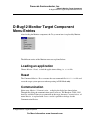
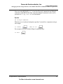
Freescale Semiconductor, Inc.
HI-WAVE
D-Bug12 Monitor
Target Component
Revised 07/17/2003
For More Information: www.freescale.com
Freescale Semiconductor, Inc.
Metrowerks, the Metrowerks logo, and CodeWarrior are registered trademarks of Metrowerks Corp. in the US and/or
other countries. All other tradenames and trademarks are the property of their respective owners.
Copyright © Metrowerks Corporation. 2003. ALL RIGHTS RESERVED.
The reproduction and use of this document and related materials are governed by a license agreement media,
it may be printed for non-commercial personal use only, in accordance with the license agreement related to the
product associated with the documentation. Consult that license agreement before use or reproduction of any
portion of this document. If you do not have a copy of the license agreement, contact your Metrowerks representative or call 800-377-5416 (if outside the US call +1-512-996-5300). Subject to the foregoing non-commercial
personal use, no portion of this documentation may be reproduced or transmitted in any form or by any means,
electronic or mechanical, without prior written permission from Metrowerks.
Metrowerks reserves the right to make changes to any product described or referred to in this document without further
notice. Metrowerks makes no warranty, representation or guarantee regarding the merchantability or fitness of its products for any particular purpose, nor does Metrowerks assume any liability arising out of the application or use of any
product described herein and specifically disclaims any and all liability. Metrowerks software is not authorized for
and has not been designed, tested, manufactured, or intended for use in developing applications where the failure, malfunction, or any inaccuracy of the application carries a risk of death, serious bodily injury, or damage
to tangible property, including, but not limited to, use in factory control systems, medical devices or facilities,
nuclear facilities, aircraft navigation or communication, emergency systems, or other applications with a similar degree of potential hazard.
USE OF ALL SOFTWARE, DOCUMENTATION AND RELATED MATERIALS ARE SUBJECT TO THE
METROWERKS END USER LICENSE AGREEMENT FOR SUCH PRODUCT.
How to Contact Metrowerks
Corporate Headquarters
Metrowerks Corporation
7700 West Parmer Lane
Austin, TX 78729
U.S.A.
World Wide Web
http://www.metrowerks.com
Sales
Voice: 800-377-5416
Fax: 512-996-4910
Email: [email protected]
Technical Support
Voice: 800-377-5416
Email: [email protected]
For More Information: www.freescale.com
Freescale Semiconductor, Inc.
Table of Contents
1 D-Bug12 Monitor Target Component
Introduction . . . . . . . . . . . . . . . .
Interfacing Your System and a Target . . . . . .
Hardware Connection . . . . . . . . . . .
Communication Configuration . . . . . . . . .
Communication Device . . . . . . . . . .
Baudrate . . . . . . . . . . . . . . . .
Show Protocol . . . . . . . . . . . . . .
Loading the D-Bug12 Monitor Target Component .
D-Bug12 Monitor Target Component Menu Entries
Loading an application. . . . . . . . . . .
Reset. . . . . . . . . . . . . . . . . .
Communication . . . . . . . . . . . . .
MCU Selection. . . . . . . . . . . . . .
Memory Configuration. . . . . . . . . . .
The HI-WAVE Status Bar for the Monitor . . .
Default Target Setup . . . . . . . . . . . . .
Monitor Default Environment . . . . . . . .
COMDEV . . . . . . . . . . . . . . .
SLAVEDELAY . . . . . . . . . . . . .
SHOWPROT . . . . . . . . . . . . . .
MCUID . . . . . . . . . . . . . . . .
EEPROM_START, EEPROM_END . . . . .
Monitor Target Component Commands . . . . .
PROTOCOL . . . . . . . . . . . . . . .
BAUDRATE. . . . . . . . . . . . . . .
PT . . . . . . . . . . . . . . . . . . .
VER . . . . . . . . . . . . . . . . . .
DEVICE . . . . . . . . . . . . . . . .
TERMINAL . . . . . . . . . . . . . . .
How works the terminal emulation? . . . . .
5
.
.
.
.
.
.
.
.
.
.
.
.
.
.
.
.
.
.
.
.
.
.
.
.
.
.
.
.
.
.
.
.
.
.
.
.
.
.
.
.
.
.
.
.
.
.
.
.
.
.
.
.
.
.
.
.
.
.
.
.
.
.
.
.
.
.
.
.
.
.
.
.
.
.
.
.
.
.
.
.
.
.
.
.
.
.
.
.
.
.
D-Bug12 Monitor Target Component
For More Information: www.freescale.com
.
.
.
.
.
.
.
.
.
.
.
.
.
.
.
.
.
.
.
.
.
.
.
.
.
.
.
.
.
.
.
.
.
.
.
.
.
.
.
.
.
.
.
.
.
.
.
.
.
.
.
.
.
.
.
.
.
.
.
.
.
.
.
.
.
.
.
.
.
.
.
.
.
.
.
.
.
.
.
.
.
.
.
.
.
.
.
.
.
.
.
.
.
.
.
.
.
.
.
.
.
.
.
.
.
.
.
.
.
.
.
.
.
.
.
.
.
.
.
.
.
.
.
.
.
.
.
.
.
.
.
.
.
.
.
.
.
.
.
.
.
.
.
.
.
.
.
.
.
.
.
.
.
.
.
.
.
.
.
.
.
.
.
.
.
.
.
.
.
.
.
.
.
.
.
.
.
.
.
.
.
.
.
.
.
.
.
.
.
.
.
.
.
.
.
.
.
.
.
.
.
.
.
.
.
.
.
.
.
.
.
.
.
.
.
.
.
.
.
.
.
.
.
.
.
.
.
.
.
.
.
.
.
.
.
.
.
.
.
.
.
.
.
.
.
.
.
.
.
.
.
.
.
.
.
.
.
.
.
.
.
.
.
.
.
.
.
.
.
.
.5
.6
.6
.6
.7
.7
.8
.8
.9
.9
.9
.9
10
11
12
12
13
13
14
14
15
15
15
15
16
16
17
17
18
18
3
Table of Contents
Freescale Semiconductor, Inc.
Monitor Target Startup File . . . . . .
M68EVB912B32 Evaluation Board . . .
Introduction . . . . . . . . . . .
Operating Modes . . . . . . . . .
How does the Communication works?.
Hardware Breakpoints . . . . . . .
M68HC12A4EVB Evaluation Board . .
.
.
.
.
.
.
.
.
.
.
.
.
.
.
.
.
.
.
.
.
.
.
.
.
.
.
.
.
.
.
.
.
.
.
.
.
.
.
.
.
.
.
.
.
.
.
.
.
.
.
.
.
.
.
.
.
.
.
.
.
.
.
.
.
.
.
.
.
.
.
.
.
.
.
.
.
.
.
.
.
.
.
.
.
.
.
.
.
.
.
.
.
.
.
.
.
.
.
.
.
.
.
.
.
.
.
.
.
.
.
.
.
2 D-Bug12 Monitor Demo
25
Debugging with the D-Bug12 Monitor on the M68HC12B32EVB and
M68HC12A4EVB Target Boards . . . . . . . . . . . . . . . . .
Technical Considerations about M68HC12B32EVB and M68HC12A4EVB.
Starting with the D-Bug12 ASCII Monitor . . . . . . . . . . . . . .
Hardware Breakpoints on M68HC12B32EVB . . . . . . . . . . . .
Index
4
19
19
19
20
21
22
23
.
.
.
.
25
26
26
30
33
D-Bug12 Monitor Target Component
For More Information: www.freescale.com
Freescale Semiconductor, Inc.
1
D-Bug12 Monitor Target
Component
Introduction
Another advanced feature of HI-WAVE for the embedded system development world
is the ability to load different Framework targets. The D-Bug12 Monitor Target
Interface is introduced in this document.
The D-Bug12 Monitor target component is an interface used by HI-WAVE to
communicate with the Target System “M68HC12B32EVB Evaluation Board” and
“M68HC12A4EVB Evaluation Board”.
With this interface, you can download an executable program from the HI-WAVE
environment to an external target system based on a Motorola MCU which will
D-Bug12 Monitor Target Component
For More Information: www.freescale.com
5
Freescale Semiconductor, Inc.
D-Bug12 Monitor Target Component
Interfacing Your System and a Target
execute it. You will also have the feedback of the real target system behavior to HIWAVE.
HI-WAVE will fully supervise and monitor the MCU of the target system i.e. control
the CPU execution. You can read and write in internal/external memory (even when
the CPU is running), single-step/run/stop the CPU, set breakpoints in the code.
NOTE
Unconcerned Components: As the code is executed by an external
MCU, memory statistics are not available with the D-Bug12 Monitor
target component. Therefore, Profiling, Coverage analysing,
watchpoints and I/O simulation will not work with the DBug12Monitor component.
Interfacing Your System and a Target
Hardware Connection
M68HC12B32EVB Evaluation Board or M68HC12A4EVB Evaluation Board must
be connected to the COM port of the host with a standard serial communication cable
connected to J3 port on M68HC12A4EVB or P1 port on M68HC12B32EVB.
The host communication port and baudrate can be configured within HI-WAVE has
explained below.
Communication Configuration
In a general way, the communication between HI-WAVE and Target System is set
automatically. In case of communication setup default, the following dialog will pop
up.
Make sure that the parameters on your host computer are correctly configured and that
the serial communication device used is set correctly.
When using the HC12B32EVB board, check if the jumpers on the Evaluation Board
are set on the right positions depends on the used EVB- or POD Mode and if the BDM
cable is connected correct in POD Mode, otherwise, any communication between HIWAVE and the target is impossible.
6
D-Bug12 Monitor Target Component
For More Information: www.freescale.com
Freescale Semiconductor, Inc.
D-Bug12 Monitor Target Component
Communication Configuration
Communication Device
If host and target are not connected, or the connection is not via the communication
device expected, a dialog box pops up in HI-WAVE as shown below.
Choose an available communication device, type it in the Communication Device edit
box, set the Baud Rate with the drop down control and click Connect. This command
only tries the communication device that you chose. If no connection can be
established on the selected baudrate, HI-WAVE tries 57600, 38400, 28800, 19200,
9600, ... 1200. The communication device chosen is saved for a later debugging
session. When clicking Cancel, the dialog box and the environment can be quit. The
default device is COM1 and the default speed is 9600 baud.
NOTE
The communication device and the baud rate saved through this
dialog override environment variables BAUDRATE and COMDEV of
the DEFAULT.ENV file.
Baudrate
set the Baud Rate with the drop down control and click Connect. This command only
tries the communication device that you chose. The communication device chosen is
D-Bug12 Monitor Target Component
For More Information: www.freescale.com
7
Freescale Semiconductor, Inc.
D-Bug12 Monitor Target Component
Loading the D-Bug12 Monitor Target Component
saved for a later debugging session. When clicking Cancel, the dialog box and the
environment can be quit. The default device is COM1.
Show Protocol
If the Show Protocol box is checked, all the commands and responses sent and
received are reported in the Command Line window.
NOTE
This feature is used by support personnel from Motorola or
Metrowerks.
NOTE
The communication device, the baud rate and the show protocol
saved through this dialog override environment variables
BAUDRATE, COMDEV and SHOWPROT of the DEFAULT.ENV
file.
Loading the D-Bug12 Monitor Target
Component
Usually the target is set in the PROJECT.INI file, where Target=d-bug12. The
D-Bug12 Monitor Component detects automatically that the target is connected to
your system. However, if nothing is detected, the dialog box mentioned above pops up
and inform you that the target is not connected, is connected to a different port or the
jumpers of the Evaluation Board are not set correctly.
If no target is set in the PROJECT.INI file or if a different target is set, you can load
the D-Bug12 Monitor Component selecting in the main menu Component | Set
Target... as shown below and choose D-bug12 in the list of proposed targets.
8
D-Bug12 Monitor Target Component
For More Information: www.freescale.com
Freescale Semiconductor, Inc.
D-Bug12 Monitor Target Component
D-Bug12 Monitor Target Component Menu Entries
D-Bug12 Monitor Target Component
Menu Entries
After loading the Monitor component, the Target menu item is replaced by Monitor.
The different entries of the Monitor menu are explained below:
Loading an application
Choose Monitor | Load... to load the application to debug, i.e. a .ABS file.
Reset
The Command Monitor | Reset executes the reset command file RESET.CMD file and
resets the target system processor when operating in POD Mode only.
Communication
Select entry Monitor | Communication... to display the dialog box shown below.
Through this dialog the communication speed can be set. The Baudrate 57600..1200
baud are available. If there is no connection to the target, the entry Communication.. of
menu Monitor is replaced with Connect and it is possible to change also the
Communication Device.
D-Bug12 Monitor Target Component
For More Information: www.freescale.com
9
Freescale Semiconductor, Inc.
D-Bug12 Monitor Target Component
D-Bug12 Monitor Target Component Menu Entries
For details about Communication Device, Baudrate and Show Protocol please see in
chapter Communication Configuration.
NOTE
When using the D-Bug12 Monitor with M68HC12B32EVB and
loading an application onto on-chip RAM in POD mode, a transfer
timing problem could occur. Sometimes the monitor is not able to
handle high transfer rates and the RAM program is written
incorrectly. Please reduce the baudrate to 38400 or lower rates to
overcome this problem.
MCU Selection
Choose D-Bug12 | Set MCU Type... to open this dialog.
10
D-Bug12 Monitor Target Component
For More Information: www.freescale.com
Freescale Semiconductor, Inc.
D-Bug12 Monitor Target Component
D-Bug12 Monitor Target Component Menu Entries
This dialog allows you to select the MCU currently used. There are two drop list
Combo controls. They show the currently selected MCU name and MCU-ID.
The information will be taken from the file MDSEMCU.INI. If a specific MCU is not
found in this file, the user is advised to update his installation.
The selection will be saved and used as default for the next session.
Memory Configuration
Choose D-Bug12 | Memory Map... to open this dialog.
This dialog shows the default configuration for the configured MCU. This setup is
automatically loaded if the Auto select box is checked. The information about the
memory layout is read from the MCU specific personality file. The personality file can
be decomposed in the following way:
D-Bug12 Monitor Target Component
For More Information: www.freescale.com
11
Freescale Semiconductor, Inc.
D-Bug12 Monitor Target Component
Default Target Setup
00nnnVvv.MEM
where nnn is the hexadecimal representation of the MCUid (3 digits) and vv is the
version number.
This file is looked up in the “PROG\MEM” subdirectory of your installation.
NOTE
At the moment, this dialog is just used to display the default memory
layout. Therefore it is not possible to modify this configuration and
all buttons are disabled except “Ok”, “Cancel” and “Help” buttons.
The HI-WAVE Status Bar for the Monitor
When the Monitor target component has been loaded, specific information are given in
the HI-WAVE status bar. The baudrate of the serial communication, the current
evaluation board Mode (EVB or POD), the CPU derivative and the HI-WAVE status
(target status) are displayed from the left to the right in the status bar.
Default Target Setup
As any other target, the Monitor target component can be loaded from the Target
menu or can be set as a default target in the PROJECT.INI file which should be
located in the working directory.
Example of PROJECT.INI file.
[DEFAULTS]
Window0=Source
Window1=Assembly
Window2=Register
Window3=Memory
Window4=Data
Window5=Command
Window6=Module
Target=D-bug12
12
0
50
50
50
0
0
0
0
0
40
70
40
65
85
50
50
50
50
50
50
50
40
40
30
30
25
20
15
D-Bug12 Monitor Target Component
For More Information: www.freescale.com
Freescale Semiconductor, Inc.
D-Bug12 Monitor Target Component
Default Target Setup
NOTE
Please see HI-WAVE Userguide for further information about the
PROJECT.INI file.
Typically the target is set in the PROJECT.INI file as shown above. However, if the
target is not defined, load the Monitor target component interactively when opening
the Component menu, choosing Set Target... and select the D-bug12 target component.
Monitor Default Environment
As any HI-WAVE component, the behavior of the Monitor target component can be
parameterized through the DEFAULT.ENV file which should be located in the
working directory. The section shown below is the sample of the DEFAULT.ENV file
concerning the Monitor target (example).
Example
BAUDRATE=19200
BAUDRATE
This parameter specifies the baudrate of the communication between host
computer and target. The default speed is 9600 baud.
Example
BAUDRATE=9600
COMDEV
The communication port to be used on the host computer can be specified using
environment variable COMDEV. COM1 is the default communication device for PCs
and /dev/ttya for UNIX systems. You can set a different device from the
following lists:
For a PC:
Any valid communication device (COM1, COM2, etc.).
Example
D-Bug12 Monitor Target Component
For More Information: www.freescale.com
13
Freescale Semiconductor, Inc.
D-Bug12 Monitor Target Component
Default Target Setup
COMDEV=COM3
For SUN:
Any valid communication device (/dev/ttya, etc.).
Example
comdev=/dev/ttyb
SLAVEDELAY
There is an environment variable SLAVEDELAY that can be set. The default value is
20 ms (milliseconds), and values up to 1000 ms are allowed. This environment
variable sets the delay that the target system uses to respond to the host. If the target
system does not react correctly with the given delay, the delay should be increased,
e.g. set the value to 100ms.
Example
SLAVEDELAY=100
SHOWPROT
If the Show Protocol is used, all the commands and responses sent and received are
reported in the command line window. If the environment variable is set to ON, Show
Protocol is activated.
Example
SHOWPROT=ON
NOTE
14
This feature is used by support personnel from Motorola or
Metrowerks.
D-Bug12 Monitor Target Component
For More Information: www.freescale.com
Freescale Semiconductor, Inc.
D-Bug12 Monitor Target Component
Monitor Target Component Commands
MCUID
If this parameter is specified, the corresponding register file is loaded from the current
working directory.
Example
MCUID=0x3C1
NOTE
The communication device, the baud rate and the show protocol
saved through the communication device dialog override
environment variables BAUDRATE, COMDEV and SHOWPROT of
the DEFAULT.ENV file.
EEPROM_START, EEPROM_END
The default EEPROM address range set for this demo version is set for the HC912B32
MCU. However, you can force this default configuration with environment variables
EEPROM_START and EEPROM_END.
Example for the HC812A4
EEPROM_START=0x1000
EEPROM_END=0x1FFF
Monitor Target Component Commands
The following commands can be entered in the STARTUP.CMD file or in the
Command Line component.
PROTOCOL
If this command is used, all the commands and responses sent and received are
reported in the command Line window.
D-Bug12 Monitor Target Component
For More Information: www.freescale.com
15
Freescale Semiconductor, Inc.
D-Bug12 Monitor Target Component
Monitor Target Component Commands
Syntax:
PROTOCOL ON|OFF
Example
PROTOCOL ON
NOTE
This feature is used by support personnel from Motorola or
Metrowerks.
BAUDRATE
With this command it is possible to change the baudrate from the command line
window.
Syntax:
BAUDRATE <baudrate>
Example
BAUDRATE 19200
PT
With the command PT (Pass Through), it is possible to use any D-Bug12 commands
(from the HIWAVE Command Line component window) which are terminated with
‘return’. That means that e.g. the commands ‘ASM’, ‘MM’ will not work from the
command line window (because several instructions can be executed and a ‘. return’
terminates the command).
Syntax
PT <D-Bug12 Command>
To set a hardware breakpoint from the command line window, type:
16
D-Bug12 Monitor Target Component
For More Information: www.freescale.com
Freescale Semiconductor, Inc.
D-Bug12 Monitor Target Component
Monitor Target Component Commands
PT USEHBR
If HIWAVE sets the next time a breakpoint (through the commands: set Breakpoint,
StepOver...) a hardware breakpoint is used.
To see all available D-Bug12 commands, type PT HELP in the Command Line.
VER
The version command displays the version of the D-Bug12 Target Interface Component, followed
by the output from the D-Bug12 'device' command.
Syntax
VER
Example:
....
D-Bug12 Target
5.3.2
Device: 912B32
EEPROM: $0D00 - $0FFF
Flash: $8000 - $FFFF
RAM: $0800 - $0BFF
I/O Regs: $0000
HC12 CPU
6.0
DEVICE
The device command is recognized and directed to the D-Bug12. No checking of the
parameters is done (this is left to the D-Bug12).
Syntax:
DEVICE <parameters>
D-Bug12 Monitor Target Component
For More Information: www.freescale.com
17
Freescale Semiconductor, Inc.
D-Bug12 Monitor Target Component
Monitor Target Component Commands
Example:
DEVICE
DG128 800 FFF 4000 FFFF 1000 1bFF 0
TERMINAL
This command enables pseudo terminal emulation. In order to simulate the terminal I/
O a work space of 6 bytes is needed. The parameter WSPAdr of this command
specifies the base address of this work space.
Syntax:
TERMINAL <WSPAdr>
Example:
TERMINAL 0x9FA
This command enables terminal emulation and the memory from 0x9FA to 0x9FF is
used as work space.
To disable this feature (default) zero can be specified as work space address:
Example:
TERMINAL 0
How works the terminal emulation?
The terminal area is three words long as shown below.
18
D-Bug12 Monitor Target Component
For More Information: www.freescale.com
Freescale Semiconductor, Inc.
D-Bug12 Monitor Target Component
Monitor Target Startup File
If the in_flag byte is not zero, this indicates that the in_char byte contains a character
sent to the application by HI-WAVE. In other words: for the application in the target,
this in_flag byte is an “input character received” flag.
If the out_flag word contains the value $5A5A, this indicates that the str_adr field
contains the address of a string the application in the target wants to send to the HIWAVE/terminal. HI-WAVE sets the out_flag to some other value once it has
processed that string to indicate that the application may continue sending data.
To use the terminal emulation with your application, you need to link your application
with “inout.o”, “terminal.o” and “termmoni.o” and use functions available in
associated sources files.
For more information and example, please see the Calculator demo program and
sources file and specially “termmoni.c” in the demo directory of the installation. The
application calc*.abs is an example which uses terminal emulation and in the file
termmoni.c the structures of the terminal area as they are defined above are used.
Monitor Target Startup File
The startup command file STARTUP.CMD is executed by HI-WAVE straight after the
D-Bug12 Monitor target driver has been loaded. This file must be located in the
working directory. You can use any HI-WAVE command in this file and take
advantage of the wide set of commands introduced in the HI-WAVE manual to setup
the target hardware before loading any application.
Example of a STARTUP.CMD file content:
wb 0x0035
0x00
wb 0x0012
0x11
baudrate 19200
protocol off
TERMINAL 0x9FA
M68EVB912B32 Evaluation Board
Introduction
The D-Bug12 Monitor supports the EVB- and the POD operating mode of the
Evaluation Board.
D-Bug12 Monitor Target Component
For More Information: www.freescale.com
19
Freescale Semiconductor, Inc.
D-Bug12 Monitor Target Component
M68EVB912B32 Evaluation Board
In EVB Mode the application loaded into to the RAM area of the Evaluation Board is
executed and controlled through HI-WAVE.
In POD Mode the Evaluation Board serves as a BDM interface between the user and a
second M68EVB912B32 board or any other M68HC12 system. In this case the W12
connector must be used as BDM output.
Operating Modes
The D-Bug12 Monitor is on-chip (HC912B32) Flash EEPROM, located in $8000$F67F and is automatically run when setting the board in EVB or POD mode.
You can reprogram the Flash EEPROM through the BOOTLOAD mode to install
your own program in this area but if you remove/overwrite the D-Bug12 monitor, HIWAVE will no longer monitor the board.
The EVB mode (jumper W3-0, W4-0) is used to debug applications loaded directly on
your board connected to your PC serial port, monitored by D-Bug12. In POD mode
(using 2 target boards), the host EVB serves as a non intrusive controller for a second
target board via the BDM interface, like an SDI interface. Therefore the BDM-OUT
connector of the host target should be connected to the BDM-IN connector of the
target board.
Note that using factory configuration memory map on the M68HC12B32EVB board,
user code/data available is 512 bytes of on-chip RAM in $800-$9FF and 768 bytes of
on-chip EEPROM in $D00-$FFF.
Jumper Settings
Jumper
Operating Mode CmdMsg
W3-0, W4-0
EVB Mode
W3-0, W4-1
POD Mode
Memory Map
In EVB Mode the application must be loaded into the memory area 0x800..0x9FF. The
memory area 0xA00..0xBFF is used by the D-Bug12 monitor program and must not
be used. In POD Mode the area 0xA00..0xBFF can also be used by the application (on
HC12B32 target only).
20
D-Bug12 Monitor Target Component
For More Information: www.freescale.com
Freescale Semiconductor, Inc.
D-Bug12 Monitor Target Component
M68EVB912B32 Evaluation Board
It is not possible to define user vectors because the interrupt vector jump table is
located in the Flash EEPROM area.
Address
Memory CmdMsg
0x0000..0x01FF
on-chip registers
0x0800..0x09FF
user RAM in EVB/POD Mode
0x0A00..0x0BFF
user RAM in POD Mode/reserved for D-Bug12 in EVB Mode
0x0D00..0x0FFF
on-chip EEPROM
0x8000..0xFFFF
on-chip Flash EEPROM
How does the Communication works?
This section describes the way HI-WAVE in the host communicates with the
M68HC12B32 Evaluation Board.
HIWAVE will use the commands which are provided from the D-Bug12 monitor
which is installed in Flash EPROM of the M68HC12B32 Evaluation board.
The following commands are used:
Function
D-Bug12 D-Bug12Command CmdMsg
read memory
upload <startadr> <endadr>
write memory
load <adr>
read register
rd
write register
<register> <value>
read PC
rd
write PC
pc <value>
set breakpoint
br <adr>
delete breakpoint
nobr <adr>
start program
g
single step
t
D-Bug12 Monitor Target Component
For More Information: www.freescale.com
21
Freescale Semiconductor, Inc.
D-Bug12 Monitor Target Component
M68EVB912B32 Evaluation Board
Function
D-Bug12 D-Bug12Command CmdMsg
halt program
POD mode: stop
EVB mode: see below
reset
POD mode: reset
EVB mode: -
Halt Program in EVB mode
To halt the program the SCI receiver interrupt is used. Before the application is
started, the ‘Receiver Interrupt Enable’ Flag is set. If now a character is sent to the
target, a SCI0 interrupt occures and the message ‘SCI0 Exception’ is sent to host
computer. If the target was running while a SCI0 interrupt occurred, the target is
restarted after the command (which triggered the interrupt) is processed. So it is
possible to read and write memory while the target is running.
User defined Vectors
Traps are not cached because the interrupt jump table is located in Flash EEPROM
(0xF7C0..0xF7CF) and so it is not possible to initialize the vector table.
Hardware Breakpoints
For monitor versions equal or bigger than ‘Monitor V2.0.2’ it exists a command
‘USEHBR’ to switch to hardware breakpoints. It is not possible to switch back to
normal breakpoints (except with a reset).
To set a normal breakpoint, the command ‘BR’ is used, e.g. BR 800
breakpoint at address 0x800
// sets a
To set a hardware breakpoint the following commands are used:
USEHBR // switch to hardware breakpoint
BR D00 // set hardware breakpoint at address 0xD00
// (EEPROM area for a M68EVB912B32 board)
NOTE
There are only two hardware breakpoints available and it is not
possible to switch back to set ‘Software’ breakpoints. To set normal
breakpoints, a reset of the board must be done.
To set a hardware breakpoint from the Command Line component window, type:
22
D-Bug12 Monitor Target Component
For More Information: www.freescale.com
Freescale Semiconductor, Inc.
D-Bug12 Monitor Target Component
M68HC12A4EVB Evaluation Board
PT USEHBR
If HIWAVE sets the next time a breakpoint (through the commands: set Breakpoint,
StepOver...) a hardware breakpoint is used.
For more information, please refer to the M68EVB912B32 Evaluation Board User’s
Manual or the M68HC12A4EVB Evaluation Board User’s Manual.
M68HC12A4EVB Evaluation Board
On the A4 board, user code/data available is 512 bytes of on-chip RAM in $800-$9FF,
4KB of on-chip EEPROM in $1000-$1FFF and 16KB of pseudo-ROM (external
RAM) in $4000-$7FFF. The D-Bug12 monitor is installed on the 32 KB external
EPROMs above address $8000.
Please make sure that jumper settings of the board are default (D-Bug12) settings and
not SDI (Background Debug Mode) settings.
For more information, please refer to the M68HC12A4EVB Evaluation Board User’s
Manual.
D-Bug12 Monitor Target Component
For More Information: www.freescale.com
23
Freescale Semiconductor, Inc.
D-Bug12 Monitor Target Component
M68HC12A4EVB Evaluation Board
24
D-Bug12 Monitor Target Component
For More Information: www.freescale.com
Freescale Semiconductor, Inc.
2
D-Bug12 Monitor Demo
Debugging with the D-Bug12 Monitor on
the M68HC12B32EVB and
M68HC12A4EVB Target Boards
This section gives an overview of debugging with the D-Bug12 Monitor on the
M68HC12B32EVB and M68HC12A4EVB Target Boards.
The Asciimon target component is an interface used by HI-WAVE to communicate
with the above boards, using the on-board D-Bug12 Monitor and communicating in
ASCII with the monitor.
With this interface, you can download an executable program from the HI-WAVE
environment to an external target system based on a Motorola MCU which will
execute it. You will also have the feedback of the real target system behavior to HIWAVE.
HI-WAVE will fully supervise and monitor the MCU of the target system i.e. control
the CPU execution. You can read and write in internal/external memory (even when
the CPU is running), single-step/run/stop the CPU, set breakpoints in the code.
NOTE
Unconcerned Components As the code is executed by an external
MCU, memory statistics are not available with the D-Bug12 Monitor
target component. Therefore, Profiling, Coverage analysing,
watchpoints and I/O simulation are not available with the DBug12Monitor component.
D-Bug12 Monitor Target Component
For More Information: www.freescale.com
25
Freescale Semiconductor, Inc.
D-Bug12 Monitor Demo
Debugging with the D-Bug12 Monitor on the M68HC12B32EVB and M68HC12A4EVB Target Boards
Technical Considerations about
M68HC12B32EVB and M68HC12A4EVB
Two debugging mode can be set with the M68HC12B32EVB board: EVB mode and
POD mode. The HI-WAVE monitor can be handle both modes.
The D-Bug12 Monitor is on-chip (HC912B32) Flash EEPROM, located in $8000$F67F and is automatically run when setting the board in EVB or POD mode.
You can reprogram the Flash EEPROM through the BOOTLOAD mode to install
your own program in this area but if you remove/overwrite the D-Bug12 monitor, HIWAVE will no longer monitor the board.
The EVB mode (jumper W3-0, W4-0) is used to debug applications loaded directly on
your board connected to your PC serial port, monitored by D-Bug12. In POD mode
(using 2 target boards), the host EVB serves as a non intrusive controller for a second
target board via the BDM interface, like an SDI interface. Therefore the BDM-OUT
connector of the host target should be connected to the BDM-IN connector of the
target board.
Note that using factory configuration memory map on the M68HC12B32EVB board,
user code/data available is 512 bytes of on-chip RAM in $800-$9FF and 768 bytes of
on-chip EEPROM in $D00-$FFF.
On the A4 board, user code/data available is 512 bytes of on-chip RAM in $800-$9FF,
4KB of on-chip EEPROM in $1000-$1FFF and 16KB of pseudo-ROM (RAM) in
$4000-$7FFF. The D-Bug12 monitor is installed on the 32 KB external EPROMs
above address $8000.
For more information, please refer to the M68EVB912B32 Evaluation Board User’s
Manual or the M68HC12A4EVB Evaluation Board User’s Manual.
Starting with the D-Bug12 ASCII Monitor
1. First close HI-WAVE if it is running then, within the Hiware Technology Tools
shell, open the project directory C:\HICROSS\DEMO\DBG12C.
2. Make sure that the board hardware settings are the default settings for D-Bug12
mode given by Motorola user manuals.
3. Then connect the M68HC12B32EVB “P1” connector or the M68HC12A4EVB
“J3” connector to the serial communication port COM1 or COM2 of your PC,
using an RS-232 cable.
26
D-Bug12 Monitor Target Component
For More Information: www.freescale.com
Freescale Semiconductor, Inc.
D-Bug12 Monitor Demo
Debugging with the D-Bug12 Monitor on the M68HC12B32EVB and M68HC12A4EVB Target Boards
4. Power supply the board with the appropriate voltage (5 Volts DC, please see
Motorola specifications).
5. Reset the board pressing the appropriate “RESET” button (S1 button on both
boards).
6. Run HI-WAVE. If the following “Error” message is displayed, it means that HIWAVE did not found the board on your COM1 port.
7. Click Ok, then HI-WAVE asks you to specify the communication port in the
following dialog.
8. In the Communication Device edit box, type “COM2”. Click the Connect button.
Note that HI-WAVE will select the highest possible baudrate by successive tries.
However, when loading a program on M68HC12B32EVB in POD mode, you should
select a baudrate not higher than 9600 for a safe data transfer.
D-Bug12 Monitor Target Component
For More Information: www.freescale.com
27
Freescale Semiconductor, Inc.
D-Bug12 Monitor Demo
Debugging with the D-Bug12 Monitor on the M68HC12B32EVB and M68HC12A4EVB Target Boards
The HI-WAVE statusbar gives the baudrate, the debugging board mode (here EVB
mode) and the monitor status.
The HI-WAVE main menu contains a Monitor entry from where your can reset the
monitor when selecting Reset, set the serial communication parameters when selecting
Connect... or load a .ABS application to debug when selecting Load...
Fibo.abs Application
At this point, you can load example programs delivered with this demo version, like
FIBO.ABS sample which can be executed on M68HC12B32EVB and
M68HC12A4EVB boards. The program is small enough to be loaded in on-chip RAM
area from $800 to $9FF (code + variables + stack).
Load and run this example as if you were running the FIBO.ABS application with the
HI-WAVE Simulator described in the HI-WAVE Simulator previous section.
Terminal Calculator Application
A second example delivered called CALCA4.ABS / CALCB32.ABS /
CALCPOD.ABS uses the Terminal component to send information type on the PC
keyboard to the application running on the board. Also information are sent back from
the running program to this Terminal window.
CALCB32.ABS and CALCPOD.ABS are for the M68HC12B32EVB board
respectively for EVB and POD modes. The programs are bigger than the FIBO.ABS
28
D-Bug12 Monitor Target Component
For More Information: www.freescale.com
Freescale Semiconductor, Inc.
D-Bug12 Monitor Demo
Debugging with the D-Bug12 Monitor on the M68HC12B32EVB and M68HC12A4EVB Target Boards
application and are therefore loaded on on-chip EEPROM, as specified in the .PRM
file in $D00-$FFF:
SECTIONS
MY_RAM = READ_WRITE 0x800 TO 0x813;
MY_ROM = READ_ONLY 0xD00 TO 0xFFF;
PLACEMENT
DEFAULT_ROM INTO MY_ROM;
DEFAULT_RAM INTO MY_RAM;
END
NOTE
The default EEPROM address range set for this demo version is set
for the HC912B32 MCU. However, you can force this default
configuration with environment variables EEPROM_START and
EEPROM_END as explained in section Programming the HC912B32
On-chip EEPROM. (e.g. for the HC812A4:
EEPROM_START=0x1000, EEPROM_END=0x1FFF.
Therefore it takes more time to download them. However, they are resident and you
can switch off the board without loosing them.
CALCA4.ABS is the same program adaptation for the M68HC12A4EVB board.
Variables and stack are in the same area but the code now is installed in pseudo-ROM
located in $4000-$7FFF:
SECTIONS
MY_RAM = READ_WRITE 0x800 TO 0x813;
MY_ROM = READ_ONLY 0x4000 TO 0x42FF;
PLACEMENT
DEFAULT_ROM INTO MY_ROM;
DEFAULT_RAM INTO MY_RAM;
END
Running the Calculator
1. Reset the board pressing the appropriate “RESET” button (S1 button on both
boards).
2. In the main menu, choose Component | Open... Terminal to open the Terminal
component.
D-Bug12 Monitor Target Component
For More Information: www.freescale.com
29
Freescale Semiconductor, Inc.
D-Bug12 Monitor Demo
Debugging with the D-Bug12 Monitor on the M68HC12B32EVB and M68HC12A4EVB Target Boards
3. In the main menu, choose Monitor | Load... CALCA4.ABS / CALCB32.ABS /
CALCPOD.ABS (two HC12 boards required as explained above) to load the
Calculator application on the appropriate board.
4. Click
to start the execution of the application.
5. In the Terminal window, “CALCULATOR” is displayed.
6. You can type now on your PC keyboard basic operations like “34 * 5” or “12
+ 23”, etc. Operators available: +, -, /, *.
7. Type
NOTE
or
to execute the operation.
The terminal memory space interface between the Terminal
component and the Calculator programs is set with the command
“TERMINAL 0x9FA” in the STARTUP.CMD file of the
C:\HICROSS\DEMO\DBG12C directory. This exchange area is
therefore in on-chip RAM. Also the stack pointer is set in main
function in calc.c with the instruction “asm LDS #0x9F9”.
Hardware Breakpoints on M68HC12B32EVB
For D-Bug12 versions equal or bigger than Monitor V2.0.2 you can use the command
USEHBR to switch to hardware breakpoints when loading a program in the Flash
EEPROM of the HC12B32EVB (software breakpoints are then no longer available,
D-Bug12 is overwritten). Then it is not possible to switch back to normal breakpoints
without resetting the board.
To set a normal breakpoint, the command ‘BR’ is used, e.g. BR 800
breakpoint at address 0x800
// sets a
To set a hardware breakpoint the following commands are used:
USEHBR // switches to hardware breakpoints
BR D00 // sets a hardware breakpoint at address 0xD00
// (EEPROM area for a M68EVB912B32 board)
NOTE
30
There are only two hardware breakpoints available and it is not
possible to switch back to set ‘Software’ breakpoints. To set normal
breakpoints, a reset of the board must be done.
D-Bug12 Monitor Target Component
For More Information: www.freescale.com
Freescale Semiconductor, Inc.
D-Bug12 Monitor Demo
Debugging with the D-Bug12 Monitor on the M68HC12B32EVB and M68HC12A4EVB Target Boards
You can use the HI-WAVE “PT” (PT for Pass Through) command to run D-Bug12
commands within HI-WAVE. Only single line D-Bug12 commands can be used as
parameter of PT. (e.g. ‘ASM’, ‘MM’ are not handled).
Syntax
PT <D-Bug12 Command>
Therefore to set a hardware breakpoint, open the Command Line component and type,
for example:
PT USEHBR
then BR D00
For example, to see all available D-Bug12 commands, type:
PT HELP
D-Bug12 Monitor Target Component
For More Information: www.freescale.com
31
Freescale Semiconductor, Inc.
D-Bug12 Monitor Demo
Debugging with the D-Bug12 Monitor on the M68HC12B32EVB and M68HC12A4EVB Target Boards
32
D-Bug12 Monitor Target Component
For More Information: www.freescale.com
Freescale Semiconductor, Inc.
Index
Symbols
H
.ABS 9
Hardware breakpoints 22
Hardware Connection 6
HI-WAVE
Status Bar 12
B
BAUD 21
BAUDRATE 7, 8, 13, 15, 16, 19
Baudrate 7
BDM 20
BR 22
Breakpoints 22
I
I/O 6, 25
J
Jumper settings 20
C
COMDEV 7, 8, 13, 15
Commands 15
Communication 10
Communication Configuration 6
Communication device 7, 8
Connection 6
Coverage 6, 25
D
d-bug12 13
d-bug12.tgt 12
DEFAULT.ENV 7, 8, 13, 15
DEVICE 17
E
EEPROM 21, 22
EEPROM_END 15
EEPROM_START 15
Environment variables 13
EVB 20, 22
EVB mode 22
M
MCU 5, 25
MCU selection 10
MCUID 15
Memory Map 20
Memory Map... 11
Modes 20
Monitor 5
Connection 7
Default target 12
Interfacing 6
Loading 8
Menu 13
Menu entries 19
Menus 12
Startup file 19
Target Configuration 19
O
Operating Modes 19, 20
P
POD 19, 22
POD mode 22
PRIORITY 14, 19
Profiling 6, 25
PROJECT.INI 8, 12
PROTOCOL 15
PT 16
F
Flash 21, 22
G
GetVersion 20
D-Bug12 Monitor Target Component
For More Information: www.freescale.com
33
Freescale Semiconductor, Inc.
S
SCI0 22
SCI0 Exception 22
SDI
Memory Configuration 11
SHOW 14
Show Protocol 8
SHOWPROT 8, 14, 15
Simulation 6, 25
SLAVEDELAY 14
STARTUP.CMD 15, 19
System interfacing 6
T
Target commands 15
TERMINAL 18
Traps 22
U
USEHBR 22
V
Variable 13
Vectors 22
VER 17
W
Watchpoint 6, 25
34
D-Bug12 Monitor Target Component
For More Information: www.freescale.com