1
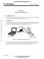
Freescale Semiconductor, Inc.
MCUEZSDI/D
Freescale Semiconductor, Inc...
September 1997
MCUez FOR
SERIAL DEBUG INTERFACE
USER’S MANUAL
© Copyright 1997 HIWARE AG; All Rights Reserved
For More Information On This Product,
Go to: www.freescale.com
Freescale Semiconductor, Inc.
Freescale Semiconductor, Inc...
Important Notice to Users
While every effort has been made to ensure the accuracy of all information in this document,
Motorola assumes no liability to any party for any loss or damage caused by errors or omissions or
by statements of any kind in this document, its updates, supplements, or special editions, whether
such errors are omissions or statements resulting from negligence, accident, or any other cause.
Motorola further assumes no liability arising out of the application or use of any information,
product, or system described herein; nor any liability for incidental or consequential damages
arising from the use of this document. Motorola disclaims all warranties regarding the information
contained herein, whether expressed, implied, or statutory, including implied warranties of
merchantability or fitness for a particular purpose. Motorola makes no representation that the
interconnection of products in the manner described herein will not infringe on existing or future
patent rights, nor do the descriptions contained herein imply the granting or license to make, use or
sell equipment constructed in accordance with this description.
Information contained in this document applies to
REVision (0) MCUez.
The computer program contains material copyrighted by Motorola Inc., first published 1997, and may
be used only under a license such as the License For Computer Programs (Article 14) contained in
Motorola’s Terms and Conditions of Sale, Rev. 1/79.
Trademarks
This document includes these trademarks:
MCUez is a trademark of Motorola Inc.
EXORciser is a trademark of Motorola Inc.
The MCUez development, emulation, and debugging application is based on HI-WAVE; a
software technology developed by HIWARE. HI-WAVE is a registered trademark of HIWARE
AG.
AIX, IBM, and PowerPC are trademarks of International Business Machines Corporation.
SPARC is a trademark of SPARC international, Inc.
Sun and SunOS are trademarks of Sun Microsystems, Inc.
UNIX is a trademark of Novell, Inc., in the United States and other countries, licensed exclusively
through X/Open Company, Ltd.
X Window System is a trademark of Massachusetts Institute of Technology.
Motorola and the Motorola logo are registered trademarks of Motorola Inc.
Motorola Inc. is an Equal Opportunity/Affirmative Action Employer.
For More Information On This Product,
Go to: www.freescale.com
Freescale Semiconductor, Inc.
CONTENTS
CONTENTS
CHAPTER 1 GENERAL INFORMATION
1.1 INTRODUCTION . . . . . . . . . . . . . . . . . . . . . . . . . . . . . . . . . . . . . . . . . . . . . . . . . . . . . . . . . . 1-1
Freescale Semiconductor, Inc...
1.2 OVERVIEW . . . . . . . . . . . . . . . . . . . . . . . . . . . . . . . . . . . . . . . . . . . . . . . . . . . . . . . . . . . . . . . 1-1
CHAPTER 2 INTERFACING YOUR SYSTEM TO A TARGET
2.1 INTRODUCTION . . . . . . . . . . . . . . . . . . . . . . . . . . . . . . . . . . . . . . . . . . . . . . . . . . . . . . . . . . 2-1
2.2 SYSTEM POWER . . . . . . . . . . . . . . . . . . . . . . . . . . . . . . . . . . . . . . . . . . . . . . . . . . . . . . . . . . 2-2
CHAPTER 3 COMMUNICATION CONFIGURATION
3.1 INTRODUCTION . . . . . . . . . . . . . . . . . . . . . . . . . . . . . . . . . . . . . . . . . . . . . . . . . . . . . . . . . . 3-1
3.2 COMMUNICATION DEVICE . . . . . . . . . . . . . . . . . . . . . . . . . . . . . . . . . . . . . . . . . . . . . . . . 3-1
3.3 DATA FORMAT . . . . . . . . . . . . . . . . . . . . . . . . . . . . . . . . . . . . . . . . . . . . . . . . . . . . . . . . . . . 3-2
CHAPTER 4 DEFAULT TARGET SETUP AND MENUS
4.1 INTRODUCTION . . . . . . . . . . . . . . . . . . . . . . . . . . . . . . . . . . . . . . . . . . . . . . . . . . . . . . . . . . 4-1
4.2 SETTING A TARGET . . . . . . . . . . . . . . . . . . . . . . . . . . . . . . . . . . . . . . . . . . . . . . . . . . . . . . . 4-2
4.3 THE MCUEZ STATUS BAR FOR THE SDI . . . . . . . . . . . . . . . . . . . . . . . . . . . . . . . . . . . . . 4-2
4.4 ADVANCED SDI ENVIRONMENT SETUP . . . . . . . . . . . . . . . . . . . . . . . . . . . . . . . . . . . . .
4.4.1 SDI Default Environment . . . . . . . . . . . . . . . . . . . . . . . . . . . . . . . . . . . . . . . . . . . . . . . . .
4.4.2 Parameters Override . . . . . . . . . . . . . . . . . . . . . . . . . . . . . . . . . . . . . . . . . . . . . . . . . . . . .
4.4.3 IMODULE . . . . . . . . . . . . . . . . . . . . . . . . . . . . . . . . . . . . . . . . . . . . . . . . . . . . . . . . . . . .
4.4.4 COMDEV . . . . . . . . . . . . . . . . . . . . . . . . . . . . . . . . . . . . . . . . . . . . . . . . . . . . . . . . . . . . .
4.4.5 SDI Target Startup File . . . . . . . . . . . . . . . . . . . . . . . . . . . . . . . . . . . . . . . . . . . . . . . . . . .
4.4.6 SDI Reset Command File . . . . . . . . . . . . . . . . . . . . . . . . . . . . . . . . . . . . . . . . . . . . . . . . .
4-3
4-3
4-3
4-3
4-3
4-3
4-4
CHAPTER 5 SDI TARGET COMPONENT MENU ENTRIES
5.1 INTRODUCTION . . . . . . . . . . . . . . . . . . . . . . . . . . . . . . . . . . . . . . . . . . . . . . . . . . . . . . . . . . 5-1
5.2 LOADING AN APPLICATION . . . . . . . . . . . . . . . . . . . . . . . . . . . . . . . . . . . . . . . . . . . . . . . 5-1
i
MCUEZSDI/D
For More Information On This Product,
Go to: www.freescale.com
Freescale Semiconductor, Inc.
CONTENTS
5.3 COMMUNICATIONS BAUD RATE . . . . . . . . . . . . . . . . . . . . . . . . . . . . . . . . . . . . . . . . . . .
5.3.1 Communication . . . . . . . . . . . . . . . . . . . . . . . . . . . . . . . . . . . . . . . . . . . . . . . . . . . . . . . . .
5.3.2 Maximum Baud Rate . . . . . . . . . . . . . . . . . . . . . . . . . . . . . . . . . . . . . . . . . . . . . . . . . . . .
5.3.3 Show Protocol . . . . . . . . . . . . . . . . . . . . . . . . . . . . . . . . . . . . . . . . . . . . . . . . . . . . . . . . . .
5.3.4 MCU Selection . . . . . . . . . . . . . . . . . . . . . . . . . . . . . . . . . . . . . . . . . . . . . . . . . . . . . . . . .
5.3.5 MCU E-Clock Frequency . . . . . . . . . . . . . . . . . . . . . . . . . . . . . . . . . . . . . . . . . . . . . . . . .
5.3.6 Memory Configuration . . . . . . . . . . . . . . . . . . . . . . . . . . . . . . . . . . . . . . . . . . . . . . . . . . .
5-1
5-1
5-2
5-2
5-2
5-3
5-4
Freescale Semiconductor, Inc...
CHAPTER 6 LOADING THE SDI COMPONENT
6.1 INTRODUCTION . . . . . . . . . . . . . . . . . . . . . . . . . . . . . . . . . . . . . . . . . . . . . . . . . . . . . . . . . . 6-1
6.2 ON-CHIP HARDWARE BREAKPOINT . . . . . . . . . . . . . . . . . . . . . . . . . . . . . . . . . . . . . . . . 6-1
6.3 EEPROM PROGRAMMING . . . . . . . . . . . . . . . . . . . . . . . . . . . . . . . . . . . . . . . . . . . . . . . . . . 6-1
CHAPTER 7 OPERATING THE EVB WITH THE SDI
7.1 INTRODUCTION . . . . . . . . . . . . . . . . . . . . . . . . . . . . . . . . . . . . . . . . . . . . . . . . . . . . . . . . . . 7-1
7.2 OPERATING THE SDI WITH THE MC68HC812A4EVB . . . . . . . . . . . . . . . . . . . . . . . . . . 7-1
7.3 OPERATING THE SDI WITH THE M68HC912B32EVB . . . . . . . . . . . . . . . . . . . . . . . . . . . 7-1
7.4 EXAMPLES . . . . . . . . . . . . . . . . . . . . . . . . . . . . . . . . . . . . . . . . . . . . . . . . . . . . . . . . . . . . . . . 7-1
CHAPTER 8 SDI COMMANDS
8.1 INTRODUCTION . . . . . . . . . . . . . . . . . . . . . . . . . . . . . . . . . . . . . . . . . . . . . . . . . . . . . . . . . . 8-1
8.2 COMMANDS . . . . . . . . . . . . . . . . . . . . . . . . . . . . . . . . . . . . . . . . . . . . . . . . . . . . . . . . . . . . . . 8-1
CHAPTER 9 OPERATING PROCEDURE
9.1 PERIODIC UPDATE FROM DATA COMPONENT CONTENT . . . . . . . . . . . . . . . . . . . . . 9-1
9.2 PERIODIC UPDATE FROM MEMORY COMPONENT CONTENT . . . . . . . . . . . . . . . . . 9-1
FIGURE
Figure 1-1. The Serial Device Interface (SDI) . . . . . . . . . . . . . . . . . . . . . . . . . . . . . . . . . . . . . . . . . 1-1
Figure 2-1. Serial Port Connector . . . . . . . . . . . . . . . . . . . . . . . . . . . . . . . . . . . . . . . . . . . . . . . . . . . . . 2-1
Figure 3-1. Communication Device Window . . . . . . . . . . . . . . . . . . . . . . . . . . . . . . . . . . . . . . . . . 3-1
Figure 4-1. Example of project.ini File . . . . . . . . . . . . . . . . . . . . . . . . . . . . . . . . . . . . . . . . . . . . . . 4-1
ii
For More Information On This Product,
Go to: www.freescale.com
MCUEZSDI/D
Freescale Semiconductor, Inc.
4-2
4-2
4-2
5-1
5-2
5-3
5-4
Freescale Semiconductor, Inc...
Figure 4-2. Selecting the Motosil Target Component . . . . . . . . . . . . . . . . . . . . . . . . . . . . . . . . . . .
Figure 4-3. The SDI Target Menu . . . . . . . . . . . . . . . . . . . . . . . . . . . . . . . . . . . . . . . . . . . . . . . . . .
Figure 4-4. SDI Status Bar . . . . . . . . . . . . . . . . . . . . . . . . . . . . . . . . . . . . . . . . . . . . . . . . . . . . . . . .
Figure 5-1. Communication Device Window . . . . . . . . . . . . . . . . . . . . . . . . . . . . . . . . . . . . . . . . .
Figure 5-2. MCU Selection Window . . . . . . . . . . . . . . . . . . . . . . . . . . . . . . . . . . . . . . . . . . . . . . . .
Figure 5-3. Setting the MCU Speed . . . . . . . . . . . . . . . . . . . . . . . . . . . . . . . . . . . . . . . . . . . . . . . . .
Figure 5-4. Memory Configuration Window . . . . . . . . . . . . . . . . . . . . . . . . . . . . . . . . . . . . . . . . . .
MCUEZSDI/D
For More Information On This Product,
Go to: www.freescale.com
iii
Freescale Semiconductor, Inc.
Freescale Semiconductor, Inc...
CONTENTS
iv
For More Information On This Product,
Go to: www.freescale.com
MCUEZSDI/D
Freescale Semiconductor, Inc.
GENERAL INFORMATION
CHAPTER 1
GENERAL INFORMATION
Freescale Semiconductor, Inc...
1.1
INTRODUCTION
The Serial Device Interface (SDI) is an interface developed by Motorola and used by MCUez
to communicate with an external system called the target system.
1.2
OVERVIEW
With this interface, you can download an executable program from the MCUez environment
to an external target system based on a Motorola MCU which will execute the program. You
will also have the feedback of the real target system behavior to MCUez.
SERIAL DEVICE
INTERFACE (SDI)
SDI
Host System
Target System
Figure 1-1. The Serial Device Interface (SDI)
MCUez supervises and monitors the target system’s MCU (for example, controls the CPU
execution). You can read and write to internal/external memory (even when the CPU is
running), single-step run and stop the CPU, and set breakpoints in the code.
MCUEZSDI/D
1-1
For More Information On This Product,
Go to: www.freescale.com
Freescale Semiconductor, Inc.
Freescale Semiconductor, Inc...
GENERAL INFORMATION
1-2
MCUEZSDI/D
For More Information On This Product,
Go to: www.freescale.com
Freescale Semiconductor, Inc.
INTERFACING YOUR SYSTEM TO A TARGET
CHAPTER 2
INTERFACING YOUR SYSTEM TO A TARGET
Freescale Semiconductor, Inc...
2.1
INTRODUCTION
The SDI interface is designed around a serial communication link. The interface is supported
by any communication device on your PC or SUN system. The SDI target driver
automatically loaded with the SDI target component handles the communication protocol
between the SDI and your system. However, you can adapt your target system to the SDI
interface. The SDI target system communication is serial. The SDI serial port 6-pin connector
for the HC12 target system is shown below. The SDI interface includes two serial port 6-pin
connectors. One serial port is the connector used for the HC12.
1
3
5
2
4
6
BGND
not connected
not connected
Vcc
Reset
Ground
Figure 2-1. Serial Port Connector for the HC12
The serial port connector for the CPU16/32 is shown below. The HC16 and
683xxx chip series use a 10-pin connector as shown below.
DS
GND
GND
RESET
VDD
1
3
5
7
9
2
4
6
8
10
DSO
DSI
FREEZE
BKPT
BERR
Figure 2-2. Serial Port Connector for the CPU16/32
MCUEZSDI/D
2-1
For More Information On This Product,
Go to: www.freescale.com
Freescale Semiconductor, Inc.
INTERFACING YOUR SYSTEM TO A TARGET
The communication protocol is defined by Motorola in the CPU 12 Reference Manual,
section 8 (Development and Debug Support).
2.2
SYSTEM POWER
Freescale Semiconductor, Inc...
The target system supplies power to the SDI. This power supply must conform to the TTL
standard. If it does not conform to the standard, the SDI must have its own power supply.
2-2
MCUEZSDI/D
For More Information On This Product,
Go to: www.freescale.com
Freescale Semiconductor, Inc.
COMMUNICATION CONFIGURATION
CHAPTER 3
COMMUNICATION CONFIGURATION
Freescale Semiconductor, Inc...
3.1
INTRODUCTION
The communication between the MCUez application and the SDI interface is set
automatically. If the default communication settings are used, the dialog shown in Figure 3-1
pops up. You must make sure that the parameters on your host computer are configured
correctly. Also check that the SDI interface is set correctly, otherwise, there will be no
communication between the MCUez application and the target.
3.2
COMMUNICATION DEVICE
If the host and target are not connected, or the connection is not made via the communication
device, a dialog box pops up in the MCUez application as shown below.
Figure 3-1. Communication Device Window
Choose an available communication device and enter it in the Communication Device edit
box. Set the baud rate with the drop down menu and click Connect. This command only tries
the communication device you selected.
If the connection is not established, a message box displays. Once the message box displays,
you can try a new communication device. Eventually, the chosen communication device that
makes a connection is saved for future debugging sessions. Click Cancel to quit the dialog
box and the environment. The default device is COM1.
MCUEZSDI/D
3-1
For More Information On This Product,
Go to: www.freescale.com
Freescale Semiconductor, Inc.
COMMUNICATION CONFIGURATION
NOTE
The communication device and the baud rate saved through this dialog override
the BAUDRATE and COMDEV environment variables of the default.env
file.
3.3
DATA FORMAT
Freescale Semiconductor, Inc...
The data format used is 8 data bits, 1 stop bit, no parity, and variable baud rate. The default
speed is 9600 baud unless defined using the SDI | Communication... menu option in the Target
menu.
3-2
MCUEZSDI/D
For More Information On This Product,
Go to: www.freescale.com
Freescale Semiconductor, Inc.
DEFAULT TARGET SETUP AND MENUS
CHAPTER 4
DEFAULT TARGET SETUP AND MENUS
Freescale Semiconductor, Inc...
4.1
INTRODUCTION
The Target menu loads the SDI target component. It can also be set as a default target in the
project.ini file. The project.ini file is located in the working directory. See the
MCUez Debugger User’s Manual for more information about the project.ini file. The
following illustration shows an example of a project.ini file.
[DEFAULTS]
Window0=Source
0
0
50
40
Window1=Assembly
50
0
50
40
Window2=Register
50
40
50
30
Window3=Memory
50
70
50
30
Window4=Data
0
40
50
25
Window5=Command
0
65
50
20
Window6=Module
0
85
50
15
Target=Motosil
Figure 4-1. Example of project.ini File
MCUEZSDI/D
4-1
For More Information On This Product,
Go to: www.freescale.com
Freescale Semiconductor, Inc.
DEFAULT TARGET SETUP AND MENUS
4.2
SETTING A TARGET
Freescale Semiconductor, Inc...
The target is usually set in the project.ini file as shown in Figure 4-1. If the target is not
defined, load the SDI target component by opening the Component menu, choosing Set
Target... and selecting the Motosil target component.
Figure 4-2. Selecting the Motosil Target Component
After loading the Motosil target component, the Target menu item is replaced with the SDI
menu item.
Figure 4-3. The SDI Target Menu
The different items on the SDI menu
SDI Target Component Menu Entries on page 5-1.
4.3
are
explained
in
detail
in
the
THE MCUez STATUS BAR FOR THE SDI
When you have loaded the SDI target component, the MCUez status bar displays the current
status of the SDI target component. Reading from the left to the right are the baud rate of the
serial communication, the MCUez running mode, the clock frequency of the target, and also
the current MCU-ID.
Figure 4-4. SDI Status Bar
4-2
MCUEZSDI/D
For More Information On This Product,
Go to: www.freescale.com
Freescale Semiconductor, Inc.
DEFAULT TARGET SETUP AND MENUS
4.4
ADVANCED SDI ENVIRONMENT SETUP
The communication between MCUez and SDI is automatically set at startup. However, it is
possible to manually set your communication and other parameters as described in the
following sections.
4.4.1
SDI Default Environment
Freescale Semiconductor, Inc...
As with any MCUez component, you can set parameters for the SDI target component
through the default.env file which must be located in the working directory. The section
shown below is a sample of the default.env file concerning the SDI (example).
BAUDRATE=57600
IMODULE=SIM
4.4.2
Parameters Override
If you do not specify these parameters, the default value is assumed (see below). This default
value can be changed individually if needed.
4.4.3
IMODULE
The MCU-ID provides the default values for the integration module. To override these values,
you must specify one of the following module types using the IMODULE parameter:
SIM, SCIM, RPSCIM, SCIM2, LIM_N_MUX, LIM_MUX, SLIM_N_MUX, SLIM_MUX.
Example:IMODULE=SIM
4.4.4
COMDEV
This parameter specifies the device to use between host and SDI. COM1 is the default
communication device for PCs and /dev/ttya is th default for UNIX systems. You can set
a different device from the following lists:
For a PC: Any valid communication device (COM1, COM2, etc.).
Example: COMDEV=COM3
For SUN: Any valid communication device (/dev/ttya, etc.).
Example: comdev=/dev/ttyb
4.4.5
SDI Target Startup File
The startup.cmd file is executed by MCUez after the SDI target driver loads. This file
must be located in the working directory. You can use any MCUez command in this file and
take advantage of the wide set of commands listed in the MCUez User’s Guide.
MCUEZSDI/D
4-3
For More Information On This Product,
Go to: www.freescale.com
Freescale Semiconductor, Inc.
DEFAULT TARGET SETUP AND MENUS
Example of a startup.cmd file content:
wb 0x0035
wb 0x0012
4.4.6
0x00
0x11
SDI Reset Command File
Freescale Semiconductor, Inc...
The reset.cmd file is executed when the Debugger is launched or when you choose Reset
in the Target/SDI menu. This file must be located in the working directory. You can use
any MCUez command in this file.
4-4
MCUEZSDI/D
For More Information On This Product,
Go to: www.freescale.com
Freescale Semiconductor, Inc.
SDI TARGET COMPONENT MENU ENTRIES
CHAPTER 5
SDI TARGET COMPONENT MENU ENTRIES
Freescale Semiconductor, Inc...
5.1
INTRODUCTION
The following sections describe all SDI target component menu entries.
5.2
LOADING AN APPLICATION
Choose the SDI | Load... menu option to load the application to debug, (for example, a .ABS
file).
5.3
COMMUNICATIONS BAUD RATE
The baud rate at which the host computer communicates with the SDI must be chosen early in
a session, because the system operates most efficiently when the baud rate is at the maximum
rate supported by the host computer. This baud rate is set automatically when MCUez starts to
communicate with the SDI. However, you can modify this baud rate as explained below.
5.3.1
Communication
Select the SDI | Communication... menu option to display the dialog box shown below. If you
know the maximum rate your host supports, select it from the drop down menu (115200 is not
supported on the SDI). Otherwise, select 57600. If communication fails, the baud rate reduces
automatically until communication works with the host computer.
Figure 5-1. Communication Device Window
MCUEZSDI/D
5-1
For More Information On This Product,
Go to: www.freescale.com
Freescale Semiconductor, Inc.
SDI TARGET COMPONENT MENU ENTRIES
5.3.2
Maximum Baud Rate
The maximum baud rate depends on the speed and interrupt load of the host computer. On
slow notebook computers or on computers running on a network, the maximum baud rate can
be as low as 19200. A buffered I/O card allows the maximum rate of 57600 on any host
computer. The default value is 9600.
Freescale Semiconductor, Inc...
5.3.3
Show Protocol
If the Show Protocol box is checked, all the commands and responses sent and received are
reported in the command line window. This feature is used by support personnel from
Motorola.
5.3.4
MCU Selection
Choose the SDI | Set MCU... menu option to open this dialog.
Figure 5-2. MCU Selection Window
This dialog allows you to select the MCU currently used. There are two drop down menus on
the Combo controls. They show the currently selected MCU name and MCU-ID. The
information will be taken from the MDSEMCU.INI file. If a specific MCU is not found in this
file, you must update your installation. This will save your selection to use as the default for
the next session.
5-2
MCUEZSDI/D
For More Information On This Product,
Go to: www.freescale.com
Freescale Semiconductor, Inc.
SDI TARGET COMPONENT MENU ENTRIES
5.3.5
MCU E-Clock Frequency
Freescale Semiconductor, Inc...
Choose the SDI | Set MCU Speed... menu option to open this dialog.
Figure 5-3. Setting the MCU Speed
This dialog shows the current setting of the E-clock frequency to be used by the MCU. This
frequency must be known by the SDI for proper communication through the BDM. This is
typically half of the crystal oscillator frequency for CPU12.
In the Edit box, you can specify the frequency to be used. When Select is clicked, the
debugger tries to verify the communication and if it fails, it will search for a valid frequency in
the following order:
16 MHz, 8 MHz, 4 MHz, 2 MHz, 1 MHz, 12 MHz, 6 MHz, 3 MHz, 1.5 MHz, 14 MHz, 10
MHz, 7 MHz, 5 Mhz.
If the communication cannot be verified, a message displays.
At startup, the debugger uses the specified frequency. When the debugger fails and the check
box Auto detect is checked, it will also try to find a fitting frequency. If it was not possible to
establish proper communication, an error message displays, followed by this dialog.
Selections are saved and used as defaults for the next session.
eSDI/D
5-3
For More Information On This Product,
Go to: www.freescale.com
Freescale Semiconductor, Inc.
SDI TARGET COMPONENT MENU ENTRIES
5.3.6
Memory Configuration
Freescale Semiconductor, Inc...
Choose the SDI | Memory Map... menu option to open this dialog.
Figure 5-4. Memory Configuration Window
The memory configuration window contains the physical setup of the target. This setup loads
automatically if the Auto select box is checked. MCUez identifies the setup through the
MCU-ID given in the previous dialog. However, you can modify this configuration,
save it, or load a different one. You can also add new fields, remove fields, or edit them.
5-4
MCUEZSDI/D
For More Information On This Product,
Go to: www.freescale.com
Freescale Semiconductor, Inc.
LOADING THE SDI COMPONENT
CHAPTER 6
LOADING THE SDI COMPONENT
Freescale Semiconductor, Inc...
6.1
INTRODUCTION
The MCUez target component monitors the SDI interface. The SDI driver loads when you
load the SDI target component. The SDI target DLL is not included in the MCUez base
installation. The SDI target component is loaded through the project.ini file or through
the Component | Set Target... menu option by choosing Motosil.
6.2
ON-CHIP HARDWARE BREAKPOINT
An on-chip hardware breakpoint module can be used to implement breakpoints. To invoke
this module to take advantage of hardware breakpoints, you must initialize the environment
variable HWBPMODULEADR in the default.env file with the address in memory of the
hardware breakpoint module. Make sure that the line is not in remark. If you are not using
hardware breakpoints and the associated module, comment out the line shown below:
Example:
HWBPMODULEADR=0x20
The SDI hardware breakpoint can only handle two breakpoints at the same time. Additional
breakpoints will be considered as software breakpoints. If you are debugging your code in
flash, you should not set more than two breakpoints.
Some actions like “stepping over” or “stepping out” use one internal breakpoint. For efficient
operation reduce the number of hardware breakpoints needed to one.
6.3
EEPROM PROGRAMMING
In order to download code or data into the EEPROM, MCUez has to know the location of this
EEPROM. To identify the location of this EEPROM, you must define the following two
environment variables:
EEPROM_START Defines the address of the first byte of the EEPROM memory.
EEPROM_END
Defines the address of the last byte of the EEPROM memory.
Example:
EEPROM_START=0x0D00
EEPROM_END=0xFFF
MCUEZSDI/D
6-1
For More Information On This Product,
Go to: www.freescale.com
Freescale Semiconductor, Inc.
LOADING THE SDI COMPONENT
This specifies the memory range of the EEPROM as 0xD000 to 0x0FFF. When writing to
these addresses, the EEPROM is automatically programmed to download a program or to
modify the memory or the variables interactively.
NOTE
Freescale Semiconductor, Inc...
The SDI does not currently support Flash programming. This feature is reserved
for future use.
6-2
MCUEZSDI/D
For More Information On This Product,
Go to: www.freescale.com
Freescale Semiconductor, Inc.
OPERATING THE EVB WITH THE SDI
CHAPTER 7
OPERATING THE EVB WITH THE SDI
Freescale Semiconductor, Inc...
7.1
INTRODUCTION
The SDI can be used together with any target system that is equipped with a Background
Debug Connector. The SDI also operates with the M68HC812A4EVB and
M68HC912B32EVB HC12 evaluation board. The EVB supports the HC124A and
HC129B32 controllers.
7.2
OPERATING THE SDI WITH THE MC68HC812A4EVB
To run the SDI with MC68HC812A4EVB, you must remove the BGND jumper in the EVB,
and you must disable the ROM chip (monitor program) by removing the chip select jumper
from the ROM socket. You must also make sure that both operating modes, MODA and
MODB, are set to low.
However, you can replace the default ROM chips with RAM chips. Consult the EVB User’s
Manual to get the correct setup for the chip select jumper and other jumpers on the EVB.
NOTE
When you connect the SDI cable to the EVB, make sure that the red-colored side
of the cable is aligned with the odd-numbered connector pins on the board.
7.3
OPERATING THE SDI WITH THE M68HC912B32EVB
To run the SDI with the M68HC912B32EVB, you must connect the SDI cable to the BDM IN
connector on the evaluation board. You must also set the operating mode as EVB or PAD.
When you select the PAD operating mode, you can then use the SDI in debugging procedures
on the target system. For detailed information, see the M68HC912B32EVB User’s Manual.
7.4
EXAMPLES
To run MCUez demo with A4EVB, you must place the jumper in the CSPO pin 2 and 3 on the
RAM socket to allocate memory from $8000. All demo programs delivered on the SDI
installation disk can be loaded and run with SDI on the EVB Board.
MCUEZSDI/D
7-1
For More Information On This Product,
Go to: www.freescale.com
Freescale Semiconductor, Inc.
Freescale Semiconductor, Inc...
OPERATING THE EVB WITH THE SDI
7-2
MCUEZSDI/D
For More Information On This Product,
Go to: www.freescale.com
Freescale Semiconductor, Inc.
SDI COMMANDS
CHAPTER 8
SDI COMMANDS
Freescale Semiconductor, Inc...
8.1
INTRODUCTION
The following sections describe all SDI commands.
8.2
COMMANDS
The SDI incorporates two commands: BAUD and RESET.
BAUD
Short:
Syntax:
baud rate
BAUD [rate]
rate: Specifies the new baud rate, and must be an integer
constant with one of the following specific values (decimal):
1200, 2400, 4800, 9600, 19200, 28800, 38400, 57600.
Description:
The BAUD command sets or displays the baud rate for communication between the system
controller and the host computer. For maximum performance, you must set the baud rate as
high as the host computer can accommodate. The maximum rate is 57600; the default baud
rate is 9600.
If you do not enter a baud rate, the command displays the Communications Baud Rate
Specification dialog window for interactive selection of the baud rate. If the host computer is
unable to support the requested baud rate, an “Out of synchronization” alert dialog box with
two options displays. If you select the ABORT option, the host software exits to windows. If
you choose the RETRY option, the 9600 baud rate is used. You can also select the baud rate
dialog window from the menu.
Example: BAUD 57600
Changes the communication baud rate to 57600, the maximum rate.
MCUEZSDI/D
8-1
For More Information On This Product,
Go to: www.freescale.com
Freescale Semiconductor, Inc.
SDI COMMANDS
Freescale Semiconductor, Inc...
RESET
Short:
Syntax:
target reset
RESET
Description: Resets the SDI target specified in the hardware reset and executes the
reset.cmd file. This command can be executed when loading the Command Line
Component or in any other command file.
NOTE
Refer to Chapter 5 of the MCUez Debugger User’s Manual for detailed
command line information.
8-2
MCUEZSDI/D
For More Information On This Product,
Go to: www.freescale.com
Freescale Semiconductor, Inc.
OPERATING PROCEDURE
CHAPTER 9
OPERATING PROCEDURE
Freescale Semiconductor, Inc...
9.1
PERIODIC UPDATE FROM DATA COMPONENT CONTENT
You can configure the debugger to periodically refresh the Data component, while the
application is running. Since the emulator ensures non intrusive access on emulated RAM,
your application continues to run in real time.
For the debugger to periodically update the content of the Data component:
•
Right click in the Data Component and select the entry 'Mode | Periodical' to open the
"Update Rate" dialog box.
•
Enter 10 in the Rate edit box and click 'OK'. The content of the Data component will
refresh each second.
•
Start the application. The Data component content is periodically refreshed during
program execution.
NOTE
Due to hardware restrictions, periodic refresh of the Data component is not
possible when hardware breakpoints or triggers are used in the emulator.
9.2
PERIODIC UPDATE FROM MEMORY COMPONENT CONTENT
To periodically update the content of the Memory component:
•
Right click in the Memory Component and select the entry 'Mode | Periodical' to open the
"Update Rate" dialog box.
•
Enter 10 in the Rate edit box and click 'OK'. The Memory component content will refresh
each second.
•
Start the application. The content of the Memory component is periodically refreshed
during program execution.
NOTE
Due to hardware restrictions, periodic refresh of Memory component is not
possible when hardware breakpoints or triggers are used in the emulator.
MCUEZMMDS/D
9-1
For More Information On This Product,
Go to: www.freescale.com
Freescale Semiconductor, Inc.
Freescale Semiconductor, Inc...
OPERATING PROCEDURE
9-2
MCUEZMMDS/D
For More Information On This Product,
Go to: www.freescale.com
Freescale Semiconductor, Inc.
INDEX
INDEX
B
P
BAUD 8-1
Baud Rate 5-1
Baud rate 3-2
BAUDRATE 3-2, 4-3
Protocol 2-1, 2-2, 5-2
R
RESET 8-2
Reset.cmd 4-4
Freescale Semiconductor, Inc...
C
COMDEV 3-2, 4-3
Communication 2-1, 5-1
Communication Baud Rate 5-1
Communication Configuration 3-1
Communication device 3-1
D
Data Format 3-2
Default.env 3-2, 4-3
E
Environment variables 4-3
EVB 7-1
EVB Examples 7-1
H
Hardware reset 8-2
I
IMODULE 4-3
S
SDI 1-1
Connection 3-1
Default target 4-1
Interfacing 2-1
Loading 6-1
Memory Configuration 5-4
Menu 4-2
Menu entries 5-1
Menus 4-1
Port 2-1
Power supply 2-2
Reset command file 4-4
Setup 4-3
Startup file 4-3
Status Bar 4-2
Target Configuration 5-1
SDI driver 2-1
Serial communication 2-1
Startup.cmd 4-3
System interfacing 2-1
L
T
Loading an application 5-1
Target 1-1
M
MCU 1-1
MCU frequency 5-3
MCU selection 5-2
mcuez.ini 4-1
Memory Map... 5-4
Menus 4-1
Motosil 4-1
V
Variable 4-3
MCUEZSDI/D
I-1
For More Information On This Product,
Go to: www.freescale.com