1
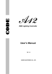
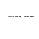
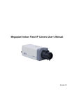
6-inch IP Speed Dome User’s Manual
Table of Contents
1
FEATURE AND FUNCTION......................................................................................... 7
1.1
General Introduction ...........................................................................................................................................7
1.2
Feature .................................................................................................................................................................7
1.2.1
Storage ............................................................................................................................................................7
1.2.2
Network Monitor .............................................................................................................................................7
1.2.3
OSD..................................................................................................................................................................7
1.2.4
Support multiple protocols ............................................................................................................................7
1.2.5
Proportional Pan and Tilt...............................................................................................................................7
1.2.6
Preset Setup and Recall ...............................................................................................................................7
1.2.7
Auto Scan........................................................................................................................................................7
1.2.8
Auto Cruise (Touring) ....................................................................................................................................7
1.2.9
Auto Pattern ....................................................................................................................................................8
1.2.10
Privacy Masking.........................................................................................................................................8
1.2.11
Action on Alarm .........................................................................................................................................8
1.2.12
Auto Flip......................................................................................................................................................8
1.2.13
Self-diagnosis ............................................................................................................................................8
1.2.14
Day/Night Mode (B/W & Color Mode) ....................................................................................................8
1.2.15
Auto Focus .................................................................................................................................................8
1.2.16
Backlight Compensation...........................................................................................................................8
1.2.17
Pan Tilt and Zoom .....................................................................................................................................8
1.2.18
3D Intelligent Location ..............................................................................................................................8
1.2.19
Idle Status...................................................................................................................................................9
1.2.20
Image Rotate..............................................................................................................................................9
2
PROTOCOL, BAUD RATE, ADDRESS SETUP......................................................... 10
2.1
Protocol and Baud Rate Setup .......................................................................................................................10
2.2
Set address dial switch ....................................................................................................................................11
3
3.1
CABLE CONNECTION............................................................................................... 12
RS485 and Power Cable Connection ............................................................................................................12
2
3.2
Alarm Cable Connection...............................................................................................................................13
3.2.1
System Layout ..............................................................................................................................................14
3.2.2
Alarm Connection.........................................................................................................................................15
3.2.3
Keyboard Connection ..................................................................................................................................16
4
QUICK CONFIGURATION TOOL .............................................................................. 18
4.1
Overview ............................................................................................................................................................18
4.2
Operation ...........................................................................................................................................................18
5
WEB OPERATION ..................................................................................................... 21
5.1
Overview ............................................................................................................................................................21
5.2
Login ...................................................................................................................................................................21
6
PERFORMANCE SPECIFICATION ........................................................................... 24
7
FUNCTION SPECIFICATION..................................................................................... 25
8
FACTORY DEFAULT SETUP .................................................................................... 28
9
SD CARD FAQ ........................................................................................................... 32
10 APPENDIX I DAILY MAINTENANCE AND IP SPEED DOME FAQ ........................... 33
10.1
Daily Maintenance ............................................................................................................................................33
10.2
FAQ.....................................................................................................................................................................33
11 APPENDIX ⅠI THUNDER PROOF AND SURGE PROTECTION................................ 34
3
12 APPENDIX ⅡI ABOUT RS485 BUS ........................................................................... 35
12.1
RS485 Bus Main Feature ................................................................................................................................35
12.2
RS485 Bus Transmission Distance................................................................................................................35
12.3
Connection Methods and Terminal Resistance ...........................................................................................35
12.4
The Problem in Practical Use..........................................................................................................................36
12.5
RS485 Bus FAQ................................................................................................................................................37
4
Welcome
Thank you for purchasing our product!
This user’s manual is designed to be a reference tool for the operation of your system.
Here you can find information about this IP speed dome features and functions.
Before installation and operation, please read the following safeguard and warning
carefully!
Important Safeguard and Warning
1.Electrical Safety
All installation and operation should conform to your local electrical safety codes.
We assume no liability or responsibility for all the fires or electrical shock caused by improper
handling or installation
2.Transportation Security
No heavy stress, violent vibration or water splash are allowed during transportation, storage and
installation.
This series product must use split type package during the transportation.
We are not liable for any damage or problem result from the integrated package during the
transportation.
3.Installation
Keep upwards. Handle with care.
Does not touch the lower dome cover; it may affect the video quality,
Do not apply power to the dome before completing installation.
4.Qualified Engineers Needed
All installation here should be done by the qualified engineers.
All the examination and repair should be done by the qualified service engineers.
We are not liable for any problems caused by unauthorized modifications or attempted repair.
6.Environment
This product has been tested and found to comply with the IP67 standard of Degrees of
protection provided by enclosure (IP Code).
The dome should be installed in a cool, dry place away from direct sunlight, inflammable,
explosive substances and etc.
7.About Camera
Camera should be installed away from direct sunlight or other strong artificial lights to avoid
blooming and smear.
When the camera is aiming at bright light or object, such as spotlight or sun, smear or blooming
may appear.
Only use mild detergent or dry cloth to clean the camera.
8. About Accessories
Always use all the accessories recommended by manufacturer.
Before installation, please open the package and check that all the components are included in
the package:
Contact you local retailer ASAP if something is missing in your package.
6
1 Feature and Function
1.1 General Introduction
This 6-inch IP dome integrates the remote network monitor function and integration high
intelligent speed dome together. It is easy to install and operate. This series IP speed dome has
vivid video and supports intelligent recognition, privacy mask, alarm activation, wide dynamic
region (WDR) function and etc. It can guarantee the stability of audio/video data and control data
transmission via network technology, so that this series product can realize real-time monitor in
anytime and at any where. Working with the built-in PTZ, the 6-inch IP speed dome can
implement the quick, accurate and convenient positioning surveillance.
1.2 Feature
This series IP speed dome has the following features:
1.2.1 Storage
z
z
z
Support central server backup function in accordance with your configuration and setup to
save audio/video data.
Support record via Web and the recorded file are storage in the client-end PC.
Support local SD card hot swap and memory backup function, support short time backup
when encounter network connection failure.
1.2.2 Network Monitor
z
z
Supports audio/video data transmit to network terminal and then decode. Audio and video
transmission protocol: HTTP, TCP, UDP, MULTICAST and RTP/RTCP and etc.
Support Web access. Max supports 10 connections.
1.2.3 OSD
z
This series IP speed dome support on-screen menu display and switch function in the Web.
It is easy for you to view dome information and configure dome, camera parameters.
1.2.4 Support multiple protocols
z
This series speed dome supports and intelligently recognize universally used protocols
PELCO-P and PELCO-D. You can use various devices (such as matrix, control keyboard
and DVR) and protocols to control the IP speed dome.
1.2.5 Proportional Pan and Tilt
z
z
This function keeps the image from moving too fast when there is a large amount of zoom.
Speed dome continually decreases or increases pan and tilt speeds in proportion to depth of
zoom. When zooms speed is increasing, the camera moving speed becomes slow. When
zooms speed is decreasing, the camera moving speed becomes fast.
1.2.6 Preset Setup and Recall
z
Preset function is to save the address information (such as PTZ pan/tilt, focus and etc) to the
memory so that you can quickly adjust the dome and PTZ to the correct position. This series
speed dome supports 200 presets.
1.2.7 Auto Scan
z
Camera scans back and forth regularly in a horizontal field. Here you need to set left and
right limit and scan speed. This series IP speed dome max supports 5 scanning paths either
via control keyboard or via the menu in screen.
1.2.8 Auto Cruise (Touring)
7
z
Auto cruise is to add presets into a routine in a desired order and then set time and stop
duration for each address. The dome will begin an auto cruise between these presets.
System supports 8 cruise paths. Each cruise consists of max 32 presets.
1.2.9 Auto Pattern
z
Auto pattern is to memorize dome operation such as pan, tilt, and zoom to repeat. Focus
and iris are in auto mode during auto pattern. This series IP speed dome supports 5 pattern
paths.
1.2.10 Privacy Masking
z
Privacy masking is a user-defined, four-sided area that can not be viewed by you. The
masking area will move with pan and tilt functions and automatically adjust in size as the
lens zooms. You can set 8 privacy masking zones (Depends on camera type).
1.2.11 Action on Alarm
z
z
This series speed dome support seven alarm inputs (normal close or normal open). Each
alarm has tree types of PTZ actions. It can be individually programmed to initiated pattern, or
go to an associated preset, cruise (touring) when received. The IP dome will return to a
previously programmed state after alarm acknowledgement or to its previous position before
alarm.
For video loss alarm or camera masking alarm, the IP speed dome can alert you according
to your setup (either pop up prompt or alarm). System can activate corresponding channel to
record video or snapshot. The alarm information will be saved in the SD card or be sent to
you via email.
1.2.12 Auto Flip
z
This function allows you to trace the object manually. As long as you continue to hold the
keyboard joystick in the down position, the dome rotates 180 degrees and repositions itself
for uninterrupted viewing of any subjects that passes directly beneath the dome.
1.2.13 Self-diagnosis
There is a self-diagnosis procedure when IP dome boots up.
z Tilt and vertical engine check
z Camera diagnostics (mainly the zoom function diagnostics)
z Display IP dome information and diagnosis information such as address, protocol,
baud rate, IP speed dome model and its self-diagnosis information and etc.
1.2.14 Day/Night Mode (B/W & Color Mode)
Auto/manual switches in low illumination.
z Auto: camera will automatically adjust CCD light level.
z Manual: use menu or function keys to select day/night mode.
1.2.15 Auto Focus
z
Auto focus allows the lens to remain in focus during zoom-in, zoom-out and motion functions
to get vivid image. You can use FAR or NEAR button to adjust focus manually.
1.2.16 Backlight Compensation
z
Balance the brightest and darkest sections of a scene to produce a more vivid picture.
1.2.17 Pan Tilt and Zoom
z
Supports zoom in and zoom out during tilt and pan movement. In this period focus and iris
are both in auto mode to get vivid video.
1.2.18 3D Intelligent Location
z
Working with DVR or WEB, just click part of the current scene, that zone will be displayed in
the central window and automatically zooms. All of these allow you to trace precisely.
8
1.2.19 Idle Status
z
When there is no available order, you can use menu to set dome idle status after specified
period. The idle status includes turn to specified preset or go to scan, cruise or pattern
function. You can set corresponding serial number for each actions.
1.2.20 Image Rotate
z
Via menu, you can realize the image rotation function so that you can view the video more
conveniently.
9
2 Protocol, Baud Rate, Address setup
Important
Before you control the IP dome via RS485, you need to set baud rate and address manually.
Otherwise you can not control this series IP dome!
If you are going to use the Web to control the IP dome, you do not need to implement the above
setup. Please refer to 6-inch IP Speed Dome Web Operation Manual (chapter 3.2.8) included in
the resources CD for detail information.
2.1 Protocol and Baud Rate Setup
Turn the IP dome transparent cover out, you can see the dial switch button in the main board.
Please configure the following settings before begin controlling dome:
z Baud rate
z Address
Note: Each time, you need to reboot the speed dome to get all the setups activated!
Open the lower dome, the interface is shown as below. See Figure 2-1.
Figure 2-1
Please refer to the protocol sheets for detailed information.
Please note, this series IP speed dome can intelligently recognize the DH-SD, PELCO-D,
PELCO-P. You do not need to set he protocol.
Protocol
1
2
3
Baud rate
5
6
4
Parity
7
8
1
2
3
4
Communication Protocol
OFF
OFF
OFF
OFF
DH-SD ( Compatible with China
industrial standard protocol)
10
ON
OFF
OFF
OFF
PELCO-D
OFF
ON
OFF
OFF
PELCO-P
X
X
X
X
Reserved
Please refer to the baud rate sheet for detailed information.
5
6
Baud Rate
OFF
OFF
9600bps
ON
OFF
4800bps
OFF
ON
2400bps
ON
ON
1200bps
Please refer to the parity setup sheet for detailed information.
7
8
Parity
OFF
OFF
NONE
ON
OFF
EVEN
OFF
ON
ODD
ON
ON
NONE
2.2 Set address dial switch
The encode mode adopts binary system. 1 to 8 is valid bit. The highest address bit is 255. You
can refer to the following sheet for more information.
Address
1
2
3
4
5
6
7
8
1
OFF
OFF
OFF
OFF
OFF
OFF
OFF
OFF
1
ON
OFF
OFF
OFF
OFF
OFF
OFF
OFF
2
OFF
ON
OFF
OFF
OFF
OFF
OFF
OFF
3
ON
ON
OFF
OFF
OFF
OFF
OFF
OFF
4
OFF
OFF
ON
OFF
OFF
OFF
OFF
OFF
5
ON
OFF
ON
OFF
OFF
OFF
OFF
OFF
6
OFF
ON
ON
OFF
OFF
OFF
OFF
OFF
7
ON
ON
ON
OFF
OFF
OFF
OFF
OFF
8
OFF
OFF
OFF
ON
OFF
OFF
OFF
OFF
……
…………………………………………………………………
254
OFF
ON
ON
ON
ON
ON
ON
ON
255
ON
ON
ON
ON
ON
ON
ON
ON
11
3 Cable Connection
3.1 RS485 and Power Cable Connection
This series IP speed dome has video cable port, RS485 control cable port, audio cable port,
network port and power port. These cables are used to transmit video output signal, RS485
control signal, audio input and output signal and connect to the network cable and power cable
and etc.
Please connect the power cable to the power socket, connect the RS485 control cable to the
RS485 port, and then connect the audio/video cable to the IP speed dome audio/video port
respectively. See Figure 3-1 and Figure 3-2.
Network Cable
Figure 3-1
Figure 3-2
Name
485
AUDIO
A
Function
485-A. It is to control IP dome built-in PTZ.
B
485-B. It is to control IP dome built-in PTZ.
GND
Ground.
OUT
Audio output port.
GND
Ground port.
IN
Audio connection port.
12
Network Port
VIDEO
GND
Ground port.
OUT
Video output port.
Power port connection interface is shown as in Figure 3-3.
Figure 3-3
Name
AC24V
Function
24V power port. Connect to the power cable.
EARTH
Ground port.
AC24V
24V power port. Connect to power cable.
Extension RS 485 port is shown as in Figure 3-4.
Figure 3-4
Name
485
Function
Extension peripheral 485 port. Such as control temperature,
humidity sensor.
Extension peripheral 485 port. Such as control temperature,
humidity sensor.
Ground port.
External device power port. Provide power to the
peripheral equipment.
+
-
GND
+12V
3.2 Alarm Cable Connection
Open the dome cover and take PTZ chip core out. Turn the core upside down; you can see the
alarm port. See Figure 3-5.
Figure 3-5
Name
Alarm out:1-2
Function
z
Two alarm output channels. When there is an alarm from current
13
channel, system activates relay or not.
z
z
Alarm output relay default setup is NO. You can use the jumpcap near the power board relay to set.
NO:Normal open alarm output.
NC:Normal close alarm output.
Alarm input ground end.
z
GND
Alarm in:1-7
z
z
z
Seven alarm input channels. They are to receive relay signal
from the external alarm source. You can go to dome menu to
activate specified preset or patter.
When the activation mode is NO (normal open), dome alarms
when there is low voltage. High voltage will not activate the
alarm.
When the activation mode is NC (normal close), dome alarms
when there is high voltage. Low voltage will not activate the
alarm.
Note:
z Dome alarm input message is ground mode.
z Dome alarm input signal are two modes: normal open and
normal close.
3.2.1 System Layout
3.2.1.1 BUS connection
Please refer to the following interface for Ethernet connection information.
Figure 3-6
Please refer to Figure 3-7 and Figure 3-8 for BUS cable connection.
14
Figure 3-7
Figure 3-8
Note:
Please use shielded twisted pair. The shielded layer shall connect to GND firmly; otherwise it
may adversely affect communication or video work.
3.2.1.2 Star Connection
Please refer to Figure 3-9 for start connection information.
Figure 3-9
3.2.2 Alarm Connection
Please refer to Figure 3-10 for alarm connection information.
15
Figure 3-10
3.2.3 Keyboard Connection
This series IP speed dome supports keyboard operation. You can use keyboard to control
the camera and PTZ. The display and control can work simultaneously. One keyboard can
control maximum 255 speed domes. Please refer to Figure 3-11.
Figure 3-11
This series speed dome protocol is open and supports multiple popular system platforms in
today’s market. Please feel free to contact us if some matrix systems do not support dome
camera communication protocol. The most direct and easy way is to use current system to
process video signal and add some control keyboards to control speed dome. See Figure 3-12.
16
Figure 3-12
17
4 Quick Configuration Tool
4.1 Overview
Quick configuration tool can search current IP address, modify IP address. At the same time, you
can use it to upgrade the device.
Please note the tool only applies to the IP addresses in the same segment.
4.2 Operation
Double click the “ConfigTools.exe”icon, you can see an interface is shown as in Figure 4-1.
In the device list interface, you can view device IP address, port number, subnet mask, default
gateway, MAC address and etc.
Figure 4-1
Select one IP address and then right click mouse, you can see an interface is shown as in Figure
4-2.
18
Figure 4-2
Select the “Open Device Web” item; you can go to the corresponding web login interface. See
Figure 4-3.
Figure 4-3
If you want to modify the device IP address without logging in the device web interface, you can
go to the configuration tool main interface to set.
In the configuration tool search interface (Figure 4-1), please select a device IP address and then
double click it to open the login interface. Or you can select an IP address and then click the
Login button to go to the login interface. See Figure 4-4.
In Figure 4-4, you can view device IP address, user name, password and port. Please modify the
corresponding information to login.
Please note the port information here shall be identical with the port value you set in TCP port in
Web Network interface. Otherwise, you can not login the device.
If you are use device background upgrade port 3800 to login, other setups are all invalid.
Figure 4-4
After you logged in, the configuration tool main interface is shown as below. See Figure 4-5.
19
Figure 4-5
For detailed information and operation instruction of the quick configuration tool, please
refer to the Quick Configuration Tool User’s Manual included in the resources CD.
20
5 Web Operation
5.1 Overview
IP speed dome support Web access via PC to manage device.
Web operation consists of the following operation sections: monitor channel, record search,
alarm setup, system setup, PTZ control and monitor window.
5.2 Login
Before web operation, please check the following items:
z PC and IP speed dome connection is OK.
z You have set PC IP address, IP speed dome IP address, subnet mask and gateway.
(Please set the IP address of the same section for the PC and IP speed dome. Please input
corresponding gateway and subnet mask if there are routers.) IP speed dome default IP
address is 192.168.1.108.
z Use order ping ***.***.***.***(IP speed dome IP address) to check connection is OK or not.
Usually the return TTL value should be less than 255.
Open IE and input device IP address in the address column. For example, if your device IP is
192.168.1.108(factory default IP address), then please input http:// 192.168.1.108 in IE address
column. See Figure 5-1.
Input your IP
address here.
Figure 5-1
System pops up warning information to ask you whether install webrec.cab control or not. Please
click yes button.
If you can’t download the ActiveX file, please modify your settings as follows. See Figure 5-2.
21
Figure 5-2
After installation, the interface is shown as below. See Figure 5-3.
Please input your user name and password.
Default factory name is admin and password is admin.
Note: For security reasons, please modify your password after you first login.
Figure 5-3
After you logged in, you can see the main window. See Figure 5-4.
There are six sections:
22
Section 1: Monitor channel menu tree
Section 2: System menu
Section3: PTZ control
Section4: Color setup and other setup
Section5: Preview window
Section 6: Monitor window switch
②
z
z
z
z
z
z
③
①
④
⑤
⑥
Figure 5-4
Please refer to 6-inch IP Speed Dome Web Operation Manual included in the resource CD for
detailed information.
23
6 Performance Specification
Specification
Index
Standard
Supported
Encode capacity
PAL : 25f/s
NTSC: 30f/s
One D1 + one CIF
D1(704*576/704*480)
HD1(352*576/352*480)
CIF(352*288/352*240)
Video
Encode bit stream
BCIF(720*288)
QCIF(176*144176*128)
QVGA(320*240)
QQVGA(160*128)
NTSC 1f/s-30f/s for each channel
(Adjustable).
PAL 1f/s-25f/s for each channel
(Adjustable)
Max supports 10 users to view
real-time video via network.
Encode Speed
Network
Network output bandwidth>
40Mbps.
Network input bandwidth>4Mbps.
Power Consumption
<50W
Power
24V AC
Temperature
-40~60ºC
Protection Level
IP66
Working Environment Humidity
Less than 90%
Package Dimension
525mm*325mm*340mm
Weight
5kg
24
7 Function Specification
Specification
Lens Control
Note
Zoom Adjustment
Manual
Focus Adjustment
Auto/Manual
Aperture Adjustment
Auto /manual
Preset
Auto Tour
Auto Pattern
Auto Scan
200
8
5
5
Auto adjusts the speed according
to the focus distance.
Tilt 90 degrees auto flip to realize
180 degrees continuing trace
Focus speed auto control
PTZ Control
Auto flip
Auto rotation speed
Manual tilt flip speed
RS485 PTZ control
0.1º~300º/s
300º
0.1º~150º/s
Baud rate: 1200/2400/4800/9600
White balance adjustment
Trace/auto/manual/indoor/outdoor
Backlight compensation control
Manual
Contrast ness adjustment
Manual
Gain
Manual
Electronic shutter control
Auto/Manual
Color/B&W(Day/Night) switch
Auto/Manual/Schedule
Preset max speed
Video Process
D1/HD1/BCIF/CIF/QCIF/VGA/
QQVGA
Max support D1 resolution.
H.264
Support motion detection zone
setup.
Support one main stream and one
extra stream.
Bidirectional Talk .Delaying value
within 200ms
Audio Listening .Support 1-ch
MIC input.
WEB Access
PPPoE
DHCP
DDNS
SMTP
Support IP address auto search
function
Resolution
Video
Video compression
Motion Detection
Dual-stream
Audio
Network
Support IP address filter function
Record
Schedule Record
6 periods in one day.
Manual Record
After enabling manual record, no
matter system is in schedule or
25
alarm status or not, system just
begins recording.
System automatically enables
recording function when alarm
occurred.
When input video changes,
system automatically enables
record operation.
Transparent value ranges from 0
to 255. O means completely
transparent and 255 is opaque.
Please refer to the above
information.
Alarm Record
Motion Detection Record
Time Title Display
OSD
Channel Title Display
Privacy Mask
Max supports 8 zones.
Local Micro SD storage .Support
high-speed card/low-speed card.
Storage
Based on SDK network storage
2-ch alarm output.
Alarm
7-ch local alarm/network alarm
input
Activate alarm via motion
detection or external input.
Please enable pre-record function
when activating the alarm
Upload JPEG file via email.
Send out alarm notice via email,
external port.
Need anti-dither supported when
alarm occurs frequently.
Support video short time buffer
storage before or after alarm Pre
record is 2Mbytes
Buffer storage video of 5s.
RS485 PTZ control .Support
semi-duplex communication way.
Event Management
Control
PTZ control via Web
Device Upgrade
Network remote
upgrade .Working wit the upgrade
tool in the resource CD.
COM upgrade. Working wit the
upgrade tool in the resource CD.
Device Management
Log in the client-end software in
the PC to monitor IPC.
Parameter Configuration
IP speed dome provides user
interface to modify device
information, video information,
record setup, motion detection
setup, alarm setup, OSD
information.
IP speed dome provides user
interface to search log, status,
user management, email setup,
time and date setup to check
26
system running information.
Important event log record. It can
record the following information:
System operation, setup
operation, alarm event, record
management, user management,
clear log.
Prevent from unauthorized data
modification.
Support
hardware/software/Watchdog
reset
Watch dog max support 35
seconds.
Log
Digital watermark
RESET
7 alarm input ports
2 alarm output ports
1 analog audio input put and 1
analog audio output port.
Interface
1 analog video port
1 network port (RJ45 10M/100M
self-adaptive Ethernet port)
1 Micro SD card port. Support
high-speed card/low-speed card.
Suspended, wall mount and
embedded installation
Installation
27
8 Factory Default Setup
Function Configuration
Type
General Setup
Encode Setup
Item Name
Default setup
Date format
Y-M-D
DST
Date separator
Time format
Language
When HDD is full
Record duration
Device No.
Video type
Main stream
Disable
‘_’
24H
Simplified Chinese
Overwrite
60M
8
PAL
Channel01
H.264
Main stream
Enable audio and video
Extra stream
Channel
Encode mode
Stream Type
Audio/Video
enable
Resolution
Frame rate
Bit stream control
Quality
Bit stream value
I frame interval
control
Stream Type
Audio/Video
enable
Resolution
Frame rate
Bit stream control
Quality
Bit stream value
I frame interval
control
Video color
Watermark
Privacy mask
Time title
Channel title
Record Setup
Channel
Pre-record
Period Setup
Start time
End time
Record
Snapshot
28
D1
25
VBR
Good
2048
50
Extra stream
Enable video
QVGA
15
VBR
Good
384
50
Brightness:50
Contrast:50
Sautratioon:50
Hue:50
Enable
Watermark: all
Watermark
type:
character
Watermark: Digital CCTV
Never
Enable.
OSD
transparent :128
Enable.
OSD
transparent :128
Ch01
5 seconds.
0:00:00
23:59:59
Period 1:Enable motion
detection/alarm
Period 1::Enable motion
TCP port
HTTP port
UDP port
Network user connection amount
Network transmission QoS
Remote host
Enable
IP address
Port
Email setup
Multiple DDNs
NAS setup
NTP setup
detection/alarm
Sunday
COM01
General
8
1
115200
None
Port 01
Disable
192.168.1.108
255.255.0.0
192.168.0.1
Device factory default
name
37777
80
37776
10
Disable
Multiple broadcast group
Disable
239.255.42.42
36666
Enable
Disable
Disable
Disable
Alarm server
Disable
Event type
Alarm input
Type
Setup
Anti-dither
General output
Alarm latch
Record channel
Record latch
Local
Input 01, disable
Normal open
Period:
Start time 0:00:00
End time:23:59:59
Period 1:enable
Week: Sunday
0 second
Disable
10 seconds
1, enable
10 seconds
Send email
Enable
PTZ activation
Disable
Event type: never
Address: 0
Disable
Motion detection
Ch01, Disable
3
Period:
Start time 0:00:00
End time:23:59:59
Period 1:enable
Week: Sunday
Week
COM Setup
Network Setup
Alarm Setup
Video Detection
Option
Function
Data bit
Stop bit
Baud rate
Parity
Ethernet
DHCP
IP address
Subnet mask
Gateway
Device name
Snapshoot
Event type
Channel
Sensitivity
Time period setup
29
Anti-dither
General output
Alarm latch
Record channel
Record latch
Send email
PTZ activation
PTZ Setup
Default and Backup
Event Type
5 seconds
Disable
10 seconds
Disable
10 seconds
Disable
Event type: Never
Address: 0
Disable
Disable
Ch01
DH-SD1
1
9600
8
1
None
Disable
Disable
Disable
Disable
Disable
Disable
Disable
Disable
Disable
Disable
No disk, disable
General Output t
Alarm Latch
Send email
Disable
10 seconds
Disable
Snapshot
Channel
Protocol
Address
Baud rate
Data bit
Stop bit
Parity
All
General
Encode
Record
COM
Network
Alarm
Video detection
Display output
Channel No.
Advanced
Abnormity
Record control
Auto. Ch1
User account
admin--- password: admin
888888--password:
888888 (reusable)
666666--password:
666666 (reusable)
Snapshot
Auto maintain
Camera Property
Channel
Snapshot mode
Frame rate
Resolution
Quality
Auto reboot
Auto delete old
files
Channel
Exposure mode
Day/night mode
Backlight compensation
White balance
30
default--password:
tluafed
Ch01
Scheduled
1f/s
D1
60%
02.00 everday
Never
1
N/A
N/A
N/A
N/A
Auto registration
DNS Setup
Signal Type
Mirror
Flip
Enable
SN
IP
Port
Device ID
DNS
Alternative DNS
Internal input
N/A
N/A
Disable
1
0.0.0.0
7000
Dahua
202.101.172.35
202.101.172.35
31
9 SD Card FAQ
Bug
SD card hot swap
Before draw out SD card, please stop record or snapshot first and
then wait for at least 15 seconds to remove the SD card.
All the operations before is to maintain data integrity.
SD
card
times
write
I can not use the
disk as the storage
media.
Do not set the SD card as the storage media to storage the
schedule record file. It may damage the SD card duration.
When disk information is shown as hibernation or capacity is 0,
please format it first (Via Web).
I can not upgrade
the
device
via
network.
The status indication light is shown as red when network upgrade
operation failed. You can use port 3800 to continue upgrade.
Recommended SD
card brand
Kingston 4GB、Kingston 1GB、Kingston 16GB、Transcend
16GB、SanDisk 1G、SanDisk 4G
Usually we recommend the 4GB (or higher) high speed card in case
the slow speed results in data loss.
32
10 Appendix I Daily Maintenance and IP Speed Dome FAQ
10.1 Daily Maintenance
Please clean dome cover regularly to get vivid image.
Handle the cover with care. Use water to wash. Don’t use cloth to clean.
Use mild detergent to clean if there is too much dust.
Note:
The sweat from your hand may erode plating surface, your nail may scrape dome cover result in
blur image.
10.2 FAQ
SYMPTOM
No self-diagnosis,
no video signal
when I connect
dome to power.
No self diagnosis.
There is a noise
Self diagnosis is ok.
No video signal
Self diagnosis is OK
but I can not operate
the dome.
Video signal loss
occurs in high speed
rotation.
Video signal is not
successive
Video is not clear.
During camera
switch, there is a tilt
movement in the
monitor.
CAUSE
Red LED is not on.
z 24V AC does not apply to
the power. Or connection is
too loose.
z Power off or Transformer
problem.
Red LED light is on
z 24V AC power is low
z Something wrong with power
socket.
Power supply is inadequate.
Mechanical malfunction.
Power connection is too loose.
Check the circuit connection.
Video switch connection is wrong
or improper operation.
Control circuit is not properly
connected
SOLUTION
z Check 24V AC power is
connected or properly
earthed.
z Check power supply condition
or check 24V transformer.
Use multimeter to check
dome load. If it is lower than
24V AC, then the IP speed
dome can not work.
z Please contact your local
retailer to replace power
socket.
Replace power socket.
Need electrical engineer help.
Connect tightly
Connect again
Please refer to user’s manual for
cable connection information.
Check control cable connection.
z
Dome address, protocol or baud
rate setup is not right.
Power supply is not sufficient
Please refer to user’s manual for
detailed setup information.
Replace power socket.
Circuit connection is too loose.
Video switch or power problem
Focus is in manual mode.
Dome cover is dirty.
Camera power is not in the same
Phase.
Connect tightly.
Need electrical engineer help.
Control manually.
Wash dome cover
When several domes are
connected to one transformer,
please connect the transformer
output cable to the domes’ same
side.
33
11 Appendix ⅠI Thunder Proof and Surge Protection
This series speed dome adopts TVS lighting protection technology. It can effectively prevent
damages from various pulse signals below 1500W, such as sudden lighting and surge. While
maintaining your local electrical safety code, you still need to take necessary precaution
measures when installing the speed dome in the outdoor environment.
z
z
z
z
z
z
The distance between the signal transmission cable and high-voltage device (or high-voltage
cable) shall be at least 50 meters.
Outdoor cable layout shall go under the penthouse if possible.
For vast land, please use sealing steel tube under the land to implement cable layout and
connects one point to the earth. Open floor cable layout is forbidden.
In area of strong thunderstorm hit or near high sensitive voltage (such as near high-voltage
transformer substation), you need to install additional high-power thunder protection device
or lightning rod.
The thunder protection and earth of the outdoor device and cable shall be considered in the
building whole thunder protection and conform to your local national or industry standard.
System shall adopt equal-potential wiring. The earth device shall meet anti-jamming and at
the same time conforms to your local electrical safety code. The earth device shall not short
circuit to N (neutral) line of high voltage power grid or mixed with other wires. When connect
the system to the earth alone, the earth resistance shall not be more than 4Ω and earth
cable cross-sectional area shall below 25 mm2. See Figure 11-1.
Figure 11-1
34
12 Appendix ⅡI About RS485 Bus
12.1 RS485 Bus Main Feature
RS485 is semi duplex communication cable of impedance 120Ω. Its max load amount is 32
effective loads (including main control device and devices to be charged).
12.2 RS485 Bus Transmission Distance
When we take 0.56mm (24AWG) twisted-pair as communication cable, the max transmission
distance (theoretically) are listed below (according to different baud rates).
Baud
Rate
2400
BPS
4800
BPS
9600
BPS
Max Distance
1800M
1200M
800M
In the following situations, the max transmission distance shall become shorter accordingly:
z The communication cable is a little bit thin;
z The surrounding environment has strong electromagnetic interference;
z There are too much devices connected to the RS485 bus;
And vice versa, the max transmission distance shall become longer.
12.3 Connection Methods and Terminal Resistance
RS485 bus requires all devices use the following connection methods. Both terminals shall have
120Ωresistance. See Figure 12-1.
Figure 12-1
Or you can refer to for the simplified way as in Figure 12-2. But the distance between “D” shall
not exceed 7M.
35
Figure 12-2
About device terminal 120Ωconnection
J2
120Ω
1-2
ON
2-3
OFF
There are 120Ωdevice terminal resistance in power socket. There are two connection ways.
The first one is shown as in Figure 12-3. It is the factory default connection method. Now the
jumper caps (connection board) are connected to the second and third socket, the 120Ω has not
connected.
1
2
3
J2
Default jumper setup (120Ω resistance has not
connected)
Figure 12-3
If you want to connect to the 120Ω resistance, you can remove the jumper caps from the second
and the third socket and then insert them to the first and second socket respectively. See Figure
12-4. Now you has connected to the 120Ωresistance.
1
2
3
J2
Jumper setup(Connect to 120Ω resistance)
Figure 12-4
12.4 The Problem in Practical Use
In practical usage, we usually adopt star type connection. The terminal resistance shall connect
to the furthest two devices (Such as device 1# and device 15# in Figure 12-5 ). But this
connection way does not conform to RS485 Bus standard. When the distances between devices
are too long, the signal reflection occurs and anti-jamming decreases, thus the signal reliability
becomes very low. You can see speed dome is not under control or speed dome is running
automatically and can not stop.
36
Figure 12-5
In this situation, we recommend RS485 distributor. This device can turn star type connection into
the connection that conforms to RS485 bus industry standard, which can avoid the above
mentioned problems and enhance communication reliability. See Figure 12-6.
Figure 12-6
12.5 RS485 Bus FAQ
Phenomenon
Speed dome
can run selfdiagnosis but I
can not control
it.
I can control
the speed
dome but is not
smooth
Possible Reasons
z Host address(baud rate) and
speed dome address(baud rate)
are not match;
z Positive and negative end of
RS485 Bus are misconnected;
z Connection cable is loose;
z RS485 Bus connection are cut
off;
z RS485 Bus connection are not
good;
z One RS485 bus is off;
z The distance between host and
speed dome is too far;
z Parallel connected too much
speed domes.
Solution
z Modify host or speed dome setup ;
z Switch RS485 positive end and
negative end;
z Fix connection cable firmly;
z Replace RS485 Bus.
z
z
z
z
Connect RS 485 Bus again;
Replace RS485 Bus;
Add terminal matching resistance;
Add RS485 distributor.
Note:
z
This manual is for reference only. Slight difference may be found in the user interface.
z
All the designs and software here are subject to change without prior written notice.
z
Please visit our website or contact your local retailer for more information.
37