1
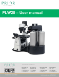
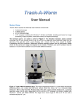
OptiScan III
Motorised Stage Systems
Manual Version 1.3
Worldwide distribution
Prior Scientific, Ltd
Prior Scientific, Inc
Prior Scientific, GmbH
Prior Scientific KK
Cambridge, UK
Rockland, MA. USA
Jena, Germany
Tokyo, Japan
T. +44 (0) 1223 881711
T. +1 781-878-8442
T. +49 (0) 3641 675 650
T. +81-3-5652-883
E. [email protected]
E. [email protected]
E. [email protected]
E. [email protected]
© Prior Scientific Instruments Ltd., UK
Version 1.3 June 2015
Page 1
Visit Prior on the web at prior.com
CONTENTS
IMPORTANT SAFETY INFORMATION SECTION 1
4
UNPACKING THE SYSTEM SECTION 2
6
2.1 OTHER ACCESSORIES
7
8
INSTALLATION SECTION 3
3.1 REMOVING AN EXISTING STAGE
8
3.2 FITTING THE OPTISCAN III STAGE
8
3.3 CABLE CONNECTIONS
9
3.4 FOCUS DRIVE INSTALLATION
10
12
GETTING STARTED SECTION 4
4.1 USB OPERATION
12
4.2 USING THE JOYSTICKS ( CS152DP)
13
ADVANCED OPERATIONS SECTION 5
15
5.1 RS232 COMMAND SET
15
5.2 MACRO AND SOAK
15
5.3 SOAK COMMAND
17
5.4 DIFFERENCES BETWEEN THE OPTISCAN III AND OPTISCAN II
18
5.5 GENERAL COMMANDS
19
5.6 STAGE COMMANDS
22
© Prior Scientific Instruments Ltd., UK
Version 1.3 June 2015
Page 2
5.7 Z AXIS COMMANDS
24
5.8 PATTERN COMMANDS
26
5.9 Z ERROR CODES .
27
5.10 CS152DP (JOYSTICK CONFIGURATION)
28
TROUBLESHOOTING SECTION 6
30
SYSTEM SPECIFICATIONS SECTION 7
33
REPLACEMENT PARTS SECTION 8
34
RETURNS AND REPAIRS SECTION 9
35
APPENDICES SECTION 10
36
A) NON STANDARD FOCUS DRIVE INSTALLATIONS
36
B) FOCUS INSTALLATION FOR LEICA DML WITH H122BL
41
C) DIRECT COUPLING FOCUS INSTALLATION FOR LEICA DMR/DML
45
D) HOW TO RUN PRIOR TERMINAL
49
Many thanks for purchasing an OptiScan III – we hope and expect that it will prove
to be useful, reliable and an asset to your microscopy work. Please do take the time
to read this manually thoroughly before attempting installation and use. This
document contains both important safety information as well as advice on how to
install and operate the product successfully to avoid damage. If you have any
problems with this product, please do not hesitate to contact Prior.
© Prior Scientific Instruments Ltd., UK
Version 1.3 June 2015
Page 3
IMPORTANT SAFETY INFORMATION
SECTION 1
•
Save this manual as it contains important safety information and
operating instructions.
• Use only as specified by these operating instructions or the intrinsic
protection provided by the unit may be impaired.
• Before using the stage system, please follow and adhere to all warnings, safety
and operating instructions located on the product and in this User Manual.
• It is safe for use in an ambient temperature from 5 to 40°C with relative
humidity (RH) to 80% up to 31°C decreasing linearly to 50% RH (relative at
40°C.
• Do not expose the product to water or moisture while energised.
• Do not expose the product to extreme hot or cold temperatures.
• Do not expose the product to open flames.
• Do not allow objects to fall on or liquids to spill on the product.
• Do not replace detachable mains supply cords by inadequately rated cords.
• Connect the AC power cord only to designated power sources as marked on
the product.
• Make sure the electrical cord is located so that it will not be subject to
damage.
• Make sure the system in installed so that the front panel power switch is easily
accessible.
• For use in a manner not specified in this manual contact Prior before any
work is done.
© Prior Scientific Instruments Ltd., UK
Version 1.3 June 2015
Page 4
• To reduce the risk of damage, unplug the product from the power source
before connecting the components together.
• DANGER - never alter the AC cord or plug. If the plug will not fit into the
outlet, have a proper outlet installed by a qualified electrician.
• Only suitably rated and approved mains cord-sets should be used as per the
country of use.
• Use only the proper type of power supply cord set (provided with the
system) for this unit.
• The OptiScan III is class 1 and must be only connected to a power outlet
which provides a protective earth (ground).
• Do not attempt to disassemble the product. Doing so will void the warranty.
This product does not contain consumer serviceable components. Service
should be performed by Authorised Service Centres.
• Only the exterior of this product should be cleaned using a damp lint-free
cloth.
• This warning sign indicates there is a high voltage
danger.
In accordance with The Waste Electrical and Electronic Equipment
Regulations, this symbol indicates that the product must not be disposed of
as unsorted municipal waste but should be collected separately.
Refer to your local authority in the EU for return and/or collection systems
available in your country.
UNPACKING THE SYSTEM
© Prior Scientific Instruments Ltd., UK
Version 1.3 June 2015
Page 5
SECTION 2
The OptiScan III System consists of the OptiScan III Controller as descried above and
one or more of the following components A-H.
Component Component Description
A
Model ES11 Control Unit
B
Model CS152DP Joystick
C
Model PS3H122 Focus Drive
D
Model ES111 Stage for Upright Microscopes includes 15 pin cable
E
Model ES107A Stage for Inverted Microscopes includes 15 pin cable
2.1 Other Accessories
© Prior Scientific Instruments Ltd., UK
Version 1.3 June 2015
Page 6
H122KLC
Solid Couple Adapter for Focus Drive on Leica
H122KBIX
Direct fine focus coupling kit for Olympus IX/BX Microscopes
H122KON
Solid Couple Adapter for Focus Drive on Olympus/Nikon
H276
RS232 cable for PC (9 or 25 pin)
H277
RS422 cable for Macintosh (8-pin Mini Din to 9 way D Type)
Note: Make sure that all of the components that should be included with your
OptiScan III System have been supplied. If parts are missing, please contact your
local Prior Dealer
INSTALLATION
© Prior Scientific Instruments Ltd., UK
Version 1.3 June 2015
Page 7
SECTION 3
3.1 Removing an Existing Stage
To avoid damage to the optics when removing an existing stage, ensure that the
distance between the objectives and stage is maximised, and that the condenser is
clear of the stage.
Removal of the stage is normally a straightforward procedure, in most cases just by
the removal of fixing screws or the loosening of a clamp screw.
3.2 Fitting the OptiScan III Stage
The Prior OptiScan III stage is supplied with a base plate insert to suit the
microscope specified. Place the stage onto the microscope stage mount and attach
using the fixing crews or clamping screw supplied. Confirm that the OptiScan III
controller unit is switched off before connecting the stage to the controller with the
lead provided (see diagrams below).
Shows the position of the OptiScan III
stage on a typical upright microscope
© Prior Scientific Instruments Ltd., UK
Version 1.3 June 2015
Page 8
Shows the position of the OptiScan III
stage on a typical inverted
microscope
3.3 Cable Connections
The cable connections to the OptiScan III controller are located on the rear panel of
the control box, as shown in the illustration below. Before making any of these
connections, ensure that the OptiScan III controller is switched off. Each connection
is labelled. Do not connect your computer's serial port cable to the `Z' axis
connector on the controller, this may damage your computer and the OptiScan III
controller. The RS232 connection from your computer should be made to the
RS232-1 port on the controller.
3.4 Focus Drive Installation
© Prior Scientific Instruments Ltd., UK
Version 1.3 June 2015
Page 9
For installation procedure for Zeiss Axio range (H122AXIO and H122AXIE), Leica
DML range (H122LB), and direct coupling models, see Appendix A.
The following instructions refer to the standard split sleeve mounting.
1. Loosen the clamp screw on the focus motor assembly and remove the focus
motor from the focus adapter.
2. Loosen the 3 socket set screws around the periphery of the focus adapter using a
2mm Allen wrench until the focus sleeve is able to fit inside the adapter. Note that it
is important to insert the sleeve in the correct orientation with the lip furthest inside
the adapter (the chamfered edge of the sleeve will be inserted first). Note the
orientation of the sleeve as it has a recess around its outer surface, which will hold
the sleeve in when the setscrews are tightened. This recess must line up with the tips
of the socket set screws.
3. With the sleeve in place, tighten the 3 socket set screws in sequence until they all
just touch the sleeve, ensuring that the split in the sleeve does not line up with any of
© Prior Scientific Instruments Ltd., UK
Version 1.3 June 2015
Page 10
the set screw positions. DO NOT TIGHTEN UP ANY OF THE SETSCREWS AT
THIS STAGE.
4. Push the adapter onto the preferred coarse knob of the microscope as far as it
will go. The controller is factory configured to drive the focus motor in the correct
direction when mounted to the right hand side of an upright microscope. If the left
hand coarse control knob is preferred by the user or the focus drive is to
be mounted on an inverted microscope, the motor direction can be reversed
by using a PC with a terminal emulation programme e.g. Prior Terminal and changing
the settings of the ZD command (see section 6) via RS232 communication.
The inside fitting diameter of the sleeve is designed to be slightly larger than the
coarse knob, provided the setscrews have not been tightened and are compressing
the sleeve.
5. While holding the adapter in place, tighten the set screws in sequence only enough
to secure the unit onto the coarse focus knob. The focus knob will have to be
rotated to gain access to all of the screws.
6. Check that the unit has been tightened sufficiently by taking hold of it and turning
it. If the adapter is correctly fitted it will stay attached to the coarse knob.
7. Slide the focus motor into the adapter as far as it will go and while applying gentle
pressure to the motor, tighten the clamp screw. This will hold the motor in place.
The rubber drive bush on the end of the motor spindle should now be pressing
against the end surface of the fine focus control knob. This can be confirmed by
manually rotating the exposed fine focus knob on the opposite side of the
microscope and feeling for the resistance caused by the detent positions of the
stepper motor as it rotates. This will not cause any damage to the focus motor.
8. Confirm that the controller is switched off before connecting the 9 way D type
plug on the focus motor lead to the socket on the rear of the controller.
© Prior Scientific Instruments Ltd., UK
Version 1.3 June 2015
Page 11
GETTING STARTED SECTION 4
Switch the OptiScan III controller unit on using the On/Off switch located on the
front panel. There are three LED’s on the bottom left of the front panel. The ‘status’
LED should be illuminated to indicate correct operation. If this is not the case refer
to section 7. The 'TX' (transmit) LED will flash rapidly when data is being transmitted
by the controller and 'RX' (receive) LED flashes rapidly when receiving data from
computer RS232.
The OptiScan III system can be controlled via RS232 serial port, USB connection or
by using the joystick. When the components are connected to the controller
correctly, the system will automatically configure itself which means that the system
can be fully operated after power on.
Control via RS232 will be considered further in Section 6.
4.1 USB Operation
Installing Prior Terminal for Windows
The USB driver software should install automatically on Windows and can be
downloaded via the Prior Website (www.prior.com) . Ensure the OptiScan III
control unit is connected to the computer via the attached USB cable and both are
turned on. A screen should appear indicating that the device driver has been
installed correctly. Afterwards, open Prior Terminal to check that it is in
communication with the computer by giving the command ‘?’.
If nothing happens then try changing the coms port (using the box in the left hand
corner of Prior Terminal’ and again type ‘?’. If there are a large number of coms
ports, or for any other reason you don’t wish to use this method, open the control
panel from the start menu, open “system” or Right-click on My Computer and
select Properties. Click on the Hardware tab. Click Device Manager. Expand
Ports (COM & LPT). You should see Prior Communication Port -> COM
device (COMn) listed, where n is the COM number assigned to the port.
More information on installing and using the software can be found in Appendix C.
© Prior Scientific Instruments Ltd., UK
Version 1.3 June 2015
Page 12
4.2 Using Joysticks (CS152DP)
The joystick unit provided as part of the OptiScan III system is a 3 axis joystick
(CS152DP) used to control the motorized stage and the focus motor.
CSI 52DP joystick – 3 axis, controls
stage and focus
The joysticks feature an X, Y joystick, two sliding tensioners and two ‘Hot Keys’.
Ensure the sliding tensioners are fully home and latched to hold the joystick vertically
in the ‘off’ position. In this position there is no power to the stage motors and the
stage does not move. Deflecting the joystick left or right from the central position
will cause the stage to move left or right in the X axis. Deflecting the joystick
backwards or forwards from the central position will cause the stage to move
backwards or forwards in the Y axis. Deflecting the joystick diagonally will cause the
stage to vector in 2 axes providing a corresponding diagonal movement.
© Prior Scientific Instruments Ltd., UK
Version 1.3 June 2015
Page 13
The joystick provides proportional control. The further the joystick is deflected from
the central position, the faster the stage will move. Deflecting the unit to its extreme
limit provides the fastest stage movement.
The ‘Hot Key’ to the left of the joystick can be used to quickly adjust the maximum
speed of the stage. This affects both X and Y axes equally. The key to the right of the
joystick provides an identical function for the focus motor.
Pressing these buttons once reduces the speed to 50% of maximum. Pressing a
second time reduces the speed to 25% of maximum and a third press of the button
returns to 100% of maximum speed. This cycle can be repeated by continuing to
press the buttons.
The action of the ‘Hot Keys’ can be reprogrammed using RS232 commands (See
Section 5.10)
The CS152DP provides a digipot control mounted to the side of the joystick unit.
This device controls the focus motor on a 3 axis system. It is not proportional, but is
designed to closely match the normal response of the fine focus knob on a
microscope.
© Prior Scientific Instruments Ltd., UK
Version 1.3 June 2015
Page 14
ADVANCED OPERATION
SECTION 5
5.1 RS232 Command Set
The OptiScan III controller can accept commands from either serial port, or USB
port (with appropriate divers installed on PC). The ports (RS232-1 & RS232-2)
default to a baud rate of 9600, this can be increased if desired (see BAUD below).
The ports can have different BAUD speeds and different compatibility mode (See
COMP Command).
Commands are terminated with a Carriage Return code <CR> (the ‘ENTER key of
the pc keyboard’).
One or more of the following delimiters separates commands from arguments.
COMMA SPACE TAB
SEMICOLON COLON
To go to position (x=100 and y=200) the user could enter any of the following
G,100,200<CR> G 100 200<CR> G 100 200<CR> G, 100, 200<CR>
G,,100,200<CR>
There are two modes of operation these are Standard, and Compatibility.
The main differences between these two modes are as follows:
In Standard mode the controller immediately returns R after any movement
command (the user has to query the controller with the $ command to determine if
the stage has stopped moving), unlike Compatibility mode where the R is only
returned after a movement has been completed.
In Standard mode movement commands can be stacked. This is not the case in
Compatibility
mode.
The Macro and Soak commands are only available in standard mode.
© Prior Scientific Instruments Ltd., UK
Version 1.3 June 2015
Page 15
Standard mode is the recommended mode for new software development and offers
more features.
Compatibility mode is supported for existing customers who do not wish to re-write
their existing application code.
All communication is non blocking so commands can always be sent although some
will not be performed immediately or indeed at all.
In Standard Mode up to 100 movement commands can be queued. This assumes that
each Command calls on 1 resource only. Each axis is defined as 1 resource apart
from the stage which is a single resource even though it constitutes 2 axes. Thus
stage and focus,are both a single resource. Commands such as G,x,y,z must be
treated as 2 commands since it uses 2 resources.
The stage defaults to moving 1 micron per supplied number. This means a move of
1000,0 would move the stage by 1mm in X.
The STAGE, and FOCUS command responses are terminated with the word END.
This will enable extra information about the OptiScan III to be added in the future
and still be readable by the Application Software.
It is recommended to treat the stage and focus as separate entities. This makes the
use of PS, and PZ preferred over P for position on the fly. This will usually be better
at the application level so each resource can be treated as a class.
5.2 Macro and Soak
MACRO - a set of commands can be entered and started in a block by the use of the
MACRO command.
A macro list can be sent by the application software. It enables consecutive actions
to be taken without any communication delay between them.
© Prior Scientific Instruments Ltd., UK
Version 1.3 June 2015
Page 16
5.3 Soak Command
Soak - this is an extension to the MACRO command enabling the testing of a
controller without tying up a PC. The soak routine continually performs the
instructions entered in a loop reporting (along the RS232 port) the number of times
round the loop on each pass. To stop the soak test, switch controller off and back
on again and the unit will complete the current pass and then stop.
Note MACRO and SOAK can only be used in Standard Mode (COMP,0)
© Prior Scientific Instruments Ltd., UK
Version 1.3 June 2015
Page 17
5.4 Differences between the OptiScan III and OptiScan II
Several hardware and software changes have been made between the two
generations of the OptiScan controller. These software changes now allow the
OptiScan III and ProScan III to use the same command structure.
• Filter wheel and shutter capability removed.
• The focus motor connection has been changed from 9 pin to 15 pin.
• The default SAZ setting changed from 4 – 40. Focus motor will drive at a
similar speed in the OptiScan and ProScan.
• USB drivers are now compatible with Windows 7.
• Default Y axis movement direction reversed.
• Sending the ‘I’ or ‘K’ command while operating in COMP,1 mode now
requires a carriage return.
• ‘VZ’ command now uses microns rather than microsteps.
Command
VZ
Arguments
Z
Response
R
Description
Sets the focus motor into constant speed of z
microns/second
• ‘CURRENT’ command added. See below.
Command
CURRENT
Arguments
a,r,s,t
Response
0
Description
Sets the drive current parameters for the given axis a.
Where a = 1,2 or 3 for X Y or Z axis.
R= running current in milliamps (1-1500)
S= standby current in milliamps (1-1500)
T = time to switch to standby current after axis has
become stationary (1-1200 ms)
CURRENT
A
0
Only use after receiving advice from Prior as setting
currents higher than that specified for the motor may
cause overheating and possibly failure.
Returns the drive current parameters for the given axis
a. Where a=1,2 or 3 for X, Y or Z axis.
E.g. “CURRENT,1 “ returns 1000, 500, 500.
© Prior Scientific Instruments Ltd., UK
Version 1.3 June 2015
Page 18
5.5 General Commands
Command
$
Argument
[a]
Response
decimal
number
Description
Reports status as a decimal number and gives motion status of
any axis of the controller. After binary conversion the
convention is as follows:
Z = D02
Y = D01
X = D00
OptiScan III treats stage (X and Y axis) as a singe resource and as
such a move in Y or X will only return 3. (X and Y are kept
separate for compatibility with ProScan. If only Z was moving 4
would be returned.
Optional parameters "$, a" where a is the axis or resource.
X - X Axis
Y - Y axis
S - X and Y axis
Z-Z axis
When the optional parameter is used the binary word is just for
the axis requested. Stage is for x,y axis.
?
None
© Prior Scientific Instruments Ltd., UK
Text string
Reports information about the peripherals currently connected
to the controller. E.g. DRIVE CHIPS 00111 means drive chops
XYZ are fitted. The information end is always a line saying END.
This allows for the addition of extra fields of information
without effecting application software. Users should always
read lines in until the END is seen. A typical response is shown
below:
OPTISCAN INFORMATION
DRIVE CHIPS 000111
JOYSTICK NOT FITTED
STAGE = NONE
FOCUS = NORMAL
FILTER_1 = NONE
FILTER_2 = NONE
SHUTTERS = 000
LED = 0000
TRIGGER = NONE
INTERPOLATOR = NONE
HARDWARE REV B
END
Version 1.3 June 2015
Page 19
Command Argument
b
96, 19, 38,
15
Response
Description
-
Set the baud rate of the port issuing the command to the value
specified by b. As a protection measure if no command is send
to the port whilst the controller is switched on, the baud rate
will revert to 9600 after switching off and back on again.
Allowable values for baud are 9600 (b=96) 19200 (b=19), 38400
(b=38) or 115200 (b=15).
WARNING: If Baud rate of the OptiScan III is changed it is
important for Application software to check communication
with OptiScan III by scanning Baud rate on initialisation. This
will avoid a permanent communications failure should the PC
Port and OptiScan III port be set at different bauds.
COMP
None
m
Report the Command protocol:
Compatibility (1)
Standard (0)
COMP
m
0
Sets the controller compatibility mode for users who want to
wait for 'R' at the end of the move. Compatibility is on if m=1
and off if m=0 . Settng COMP,1 will result in less flexibility, for
example SOAK cannot be used and commands are lost when
joystick is active. Compatibility mode is offered for users who
wish commands to be compatible with H127/H128 Prior
Controllers. Recommendation for new users is to use COMP,0
mode.
DATE
None
Text string
Reports instrument name, version number and compile time.
Note that the system description refers to the presence or
absence of internal drivers not which peripherals are
connected. E.g. ES10XYZ2 is capable of driving but not de facto
connected to an XY stage and a focus motor.
A typical response is shown below.
Prior Scientific Instruments OptiScan ES11XYZ controller
Version 0.5 compiled Apr 2 2015 12:08:01
Application can parse input string for ES10 or ES11 strings to
determine what generation controller is fitted.
ERROR
h
0
© Prior Scientific Instruments Ltd., UK
Sets the reporting of error to readable text is h =1 otherwise
error codes are returned.
Version 1.3 June 2015
Page 20
Command Argument
Response
Description
I
None
R
Stops movement in a controlled manner. The command queue
is also emptied.
K
None
R
Stops movement with no regard for position (not
recommended). The command queue is also emptied.
Reports whether any limit switch is currently active. A limit
switch is active if the switch is in contact with the axis
hardware.
Nm is a two digit Hex number (one Byte) which when
converted to binary is as follows:D07 D06 D05 D04 D03 D02 D01 D00
n/a n/a -Z +Z -Y +Y -X +X
LMT
None
Nm
MACRO
None
SERIAL
None
SOAK
None
VERSION
None
Ddd
Reports the units version number as a 3 figure number. E.g.
041 IS Version 0.41
WAIT
t
0
Inserts a wait of t milliseconds in a macro/soak routine.
0
Nnnn
0
© Prior Scientific Instruments Ltd., UK
eg 05 means stage is in contact with +X and +Y limit switches,
0A indicates contact with both -X and –Y limits. 00 means all
axes are not in contact with any limit switch. (Note that the
controller knows whether the limit switch is normally low or
normally high and corrects accordingly. This does not return
the hardware signal level of the limit switch (see STAGE
command).
Toggles the macro entering mode. Only available in standard
mode.
Reports the unit's serial number nnnn - if the serial number
has not been set "0" is returned.
Used to soak test the controller and auxiliaries. Only available
in standard mode.
Version 1.3 June 2015
Page 21
5.6 Stage commands
Command Arguments
Response
Description
B
None
Response
Moves back by one step as defined by the'X' comment below
B
y
Response
Moves back by y steps
F
BLSH
None
s,b
R
0
BLSH
s
0
Moves forward by one step as defined by the 'X' command below
Sets the stage backlash value for stage move commands sent via
the serial port (not joystick moves) to b. s = 1 enables backlash s =
0 disables backlash. B is a number of microsteps of the motor.
There are 100,000microsteps per revolution of the motor on a
standard OptiScan system.
Enables / Disables the Stage (XY) backlash. S = 1 enables backlash
s=0 disables backlash.
BLSH
None
s,b
Reports back s and b values for stage moves sent via the serial
port (see above). In COMP 1 mode only s returned.
BLSJ
s,b
0
Sets the stage backlash value for joystick moves to b in
microsteps. s = 1 enables backlash s = 0 disables backlash.
BLSJ
s
0
Enables / Disables the stage backlash for joystick moves. S = 1
enables backlash s = 0 disables backlash.
BLSJ
None
s,b
Reports back s and b for Stage (see above). In COMP 1 mode only
s returned
J
None
0
JXD
c
0
JXD
JYD
None
d
c
0
JYD
L
None
None
d
R
Turns ON the joystick (stage and z axes). This command is acted
on immediately.
Sets the direction of X axis under joystick control.
c = 1 Joystick right, moves stage mechanically right
c = -1 Joystick right, moves stage mechanically left.
Reads c.
Sets the direction of Y axis under joystick control
c = 1 Joystick forward, moves stage mechanically forward. c = -1
Joystick forward, moves stage mechanically back.
Reads d.
Moves Left by u steps as defined by the ‘X’ command.
L
M
O
x
None
s
R
R
0
SMS
=
None
None
m
n
STAGE
None
Test String
© Prior Scientific Instruments Ltd., UK
Move left by x steps
Moves stage and focus to zero (0,0,0)
Sets the speed of the stage under joystick control. S is percentage
in range 1 to 100.
Reports the current Stage (x,y) maximum speed setting m
Reports whether any limit switch has been hit since the last call of
this command. N is a decimal number which when converted to
binary is as follows:
D05
D0$ D03 D02 D01 D00
-Z
+Z
-Y
+Y
-X
+X
Reading this status clears it.
Prints information about the currently connected stage. There are
250 microsteps per full step. The information end is always a line
saying END. This allows fir te addition of extra fields of
information without effecting application software. Users should
always read lines in until the END is seen.
STAGE=ES110/1
TYPE = 12
X = 102 MM Y=53MM
MICROSTEPS/MICRON=100
END
Version 1.3 June 2015
Page 22
Command
Argument
Response
O
None
s
P
None
x,y,z
P
x,y,z
0
Reports position of x,y and z axis
Sets absolute position for x,y and z axis. No axis can be moving
for this command to work
PS
None
x,y
Reports position of Stage only (x, and y)
PS
x,y
0
PX
None
x
Px
x
0
PY
None
y
PY
Y
0
R
None
R
Moves right by one step as defined by 'X' command.
R
x
R
Move Right by x steps
SAS
a
0
SAS
none
a
SMS
m
0
X
None
u,v
X
u,v
0
SIS
none
R
Description
Reports value of O allowing for joystick speed buttons effect (if
the button speed is 1/2 and O is set to 50 the returned value
will be 25).
Sets Absolute position of x and y axis. This command will only
work is no axis is moving.
Reports position of X only.
Sets Absolute position of x axis. No axis can be moving for this
command to work.
Reports position of Y only.
Sets absolute position of y axis. This command will only work is
no axis is moving.
Set the current stage (x,y) acceleration to a. Range is 4 to 100.
RIS
none
R
VS
x,y
R
© Prior Scientific Instruments Ltd., UK
Reports the current Stage(x,y) acceleration setting a.
Sets the current stage (x,y) maximum speed to m. Range is 1 to
100.
Reports the current ste size in x and y for the stage, used in
conjunction with L,R,FB
Sets the current step size for the stage, used in conjunction
with L,R,F,B.
Set Index of Stage. The stage will move to hardware limits, stop
and set absolute position to 0,0. Used only when the
mechanical position of the stage bears no relationship to the
controller position; i.e. If the stage has been mechanically
moved during power off.
THIS COMMAND MUST BE DONE ONCE AT INITIAL
CONNECTION OF STAGE TO CONTROLLER IN ORDER TO
ESTABLISH A UNIQUE REFERENCE POSITION WHICH IS
PERMANENTLY REMEMBERED BY THE CONTROLLER
Restore Index of Stage. Used to restore accurate mechanical
position by seeking hardware limits and returning back to
controller position. This is used to to re-establish mechanical
accuracy by referencing back to the limits.
Move the stage at constant velocity in X,Y as specified by
parameters. Units are in microns/s.
VS,0,0 will bring the stage to rest. This can be used to simulate
a joystick operation from your application.
Version 1.3 June 2015
Page 23
5.7 Z-Axis Commands
Command Arguments Response
Description
BLZH
s,b
0
BLZH
s
0
Sets the Z backlash value for host moves to b in microsteps.
S=1 enables backlash. S=0 disables backlash.
Enables/disables the z backlash. S=1 enables backlash. S=0
disables backlash
BLZH
None
sb
Reports back the Z backlash value for host moves.
BLZJ
s,b
0
Sets the Z backlash value for joystick to b in microsteps. S=1
enables backlash s=0 disables backlash
BLZJ
None
s,b
Reports back s and b for Z axis (see above)
C
None
w
Reports the current step size for the focus motor.
C
w
0
Sets the current step size for the focus motor w
D
z
R
Moves Down by z steps
D
None
R
Moves down one step as defined by the 'C' command.
H
None
0
Turns OFF the joystick (Stage and Z axes) after completion of
any current joystick move. Joystick is re-enabled using the 'J'
command. The joystick is re-enabled each time the controller
is powered up
I
None
R
Stops movement in a controlled manner to reduce the risk
of losing position. The command queue is also emptied
J
None
0
Turns ON the joystick (stage and Z axes). This command is
acted on immediately.
JZD
d
0
Sets the direction of Z axis under digipot control. D=1 or D=1.
JZD
None
d
Reads d
K
None
R
M
None
R
Stops movement with no regard for position (not
recommended). The command queue is also emptied.
Moves stage and focus to zero. (0,0,0)
OF
s
0
Sets the speed of the focus motor under joystick/digipot
controls. S is percentage in range 1 to 100.
OF
None
s
Reports value of OF allowing for joystick speed buttons effect
(if the button speed is 1/2 and OF is set to 50 the returned
value will be 25).
PZ
PZ
None
z
z
0
Reports position of Z only
Sets absolute position of z axis. No axis can be moving for
this command to work. If there is an encoder on Z the
position is only set when the current position is in the
encoder range (it must have been further down than it is
currently).
© Prior Scientific Instruments Ltd., UK
Version 1.3 June 2015
Page 24
Command
Argument Response
Description
SAZ
a
0
Set the current Z acceleration to a. Range is 4 to 100.
FOCUS
None
Test string
Prints information about focus unit. There are 250 microsteps
per full step. The information end is always a line saying END.
This allows for the addition of extra fields of information
without effecting application software. Users should always
read lines in until the END is seen.
SAZ
None
a
FOCUS = NORMAL
TYPE = 0
MICRONS/REV = 100
Reports the current Z acceleration setting (a)
SMZ
None
m
Report s the current Z maximum speed setting (m)
SMZ
m
0
Sets the current Z maximum speed to m. Range is 1 to 100.
SAZ
None
a
Report the current Z acceleration setting
SMZ
None
m
Report the current Z maximum speed setting (m).
U
z
R
Moves up by z steps
U
None
R
Moves up by on step as defined by the 'C' command.
V
z
R
Go to the absolute position z, in steps.
VZ
z
R
Z
None
0
Move the focus at constant velocity as specified by
parameters. Units are in microns/s.
VZ,0 will bring the focus to rest. Tis can be used to simulate a
joystick digipot operation from your application. UPR must be
set correctly for this to work.
Sets the stage and focus to absolute position to Zero (0,0,0).
ZD
d
0
ZD
None
d
© Prior Scientific Instruments Ltd., UK
d=1 Sets direction of rotation of focus motor. Defaults to 1 and
is correct for motor fitted on right hand side of microscope.
D=-1 Direction of rotation of focus motor opposite to above.
Returns d
Version 1.3 June 2015
Page 25
5.8 Pattern Commands
Command Arguments Response
Description
E
None
R
Sets the origin for the pattern to the current position. Zeroes
the pattern X and Y counter.
N
n,m
0
Fixes the number n of X and number m of Y steps for the
pattern
N
None
n,m
Reports number of X and Y steps
Q
None
0
Sets the origin of the disc grid equal to the current position.
Zeros the disc grid X and Y counter.
S
None
R
Move to next position in rectangular raster
S
?
s
Step number of scan
S
T
n,m
None
R
Moves to nth cell in X and mth cell in Y
R
Move to next field of disc raster scan.
T
?
W
d
s
0 in comp
mode, number
of steps in
standard mode.
Step number s of circular scan
Sets the diameter in mm of a circular dist (range 1 to 327 mm)
w
none
d
reports the disc diameter (in mm)
x
x,y
0
sets the step size in X and Y
X
None
x,y
Reports step size in X and Y
Y
None
R
Move to next position of rectangular snake
Y
?
s
Step number of scan
Y
n,m
R
Moves to nth cell in X and mth cell in Y
© Prior Scientific Instruments Ltd., UK
Version 1.3 June 2015
Page 26
5.9 Error Codes
If a command is not valid a response of “E,n” is returned the n specifying an error
type as listed below.
Machine or human readable messages are chosen using the ERROR Command
ERROR
ERROR DESCRIPTION
CODE
1
NO STAGE
2
NOT IDLE
3
NO DRIVE
4
STRING PARSE
5
COMMAND NOT FOUND
6
NOT APPLICABLE
7
NO FOCUS
8
VALUE OUT OF RANGE
9
NOT APPLICABLE
10
ARG1 OUT OF RANGE
11
ARG2 OUT OF RANGE
12
ARG3 OUT OF RANGE
13
ARG4 OUT OF RANGE
14
ARG5 OUT OF RANGE
15
ARG6 OUT OF RANGE
16
INCORRECT STATE
17
NOT APPLICABLE
18
QUEUE FULL
19
COMPATIBILITY MODE SET
20
NOT APPLICABLE
21
INVALID CHECKSUM
60
NOT APPLICABLE
61
NOT APPLICABLE
© Prior Scientific Instruments Ltd., UK
Version 1.3 June 2015
Page 27
5.10 CS152DP (Joystick Configuration)
CS152DP
2 axis joystick with digipot for Z axis.
The BUTTON Command described below can be used to change the function of any
of the buttons of the joystick.
b=0 Button released.(i.e. changing to a state where no button
is pressed)
b=1 Right button pressed b=2 Left button pressed
(Pressing more than one button simultaneously is not allowed.) f defines what action
the controller does when it first detects a new state given by b above.
f= 0 Default Button Function
f= 1 Z motor velocity stop (only used in conjunction with f=2 and f=3 below)
f= 2 Z motor constant velocity up
f= 3 Z motor constant velocity down
f= 4 Toggles digipot speed 100%, 50% 25%
f= 5 Toggles X/Y joystick speed 100%, 50%, 25%
f= 6 Toggles joystick speed 100% 10%
f= 7 Toggles joystick speed 100% 2%
f= 8 Moves Z motor up by amount defined by C Command
f= 9 Moves Z motor down by amount defined by C Command
f=10 Moves stage left defined by X Command
f=11 Moves stage right defined by X Command
f=12 Moves stage back defined by X Command
f=13 Moves stage front by amount defined by X Command
f=14 Toggles Digipot Speed 100% 10%
f=15 Toggles Digipot Speed 100% 2% Examples:
Right button(b=1) being pressed moves Z up at constant velocity
Left button(b=2) being pressed moves Z down at constant velocity
Release buttons (b=0) stops Z motor (no buttons being pressed.)
Right button (b=1)toggles joystick speed 100%-2%
© Prior Scientific Instruments Ltd., UK
Version 1.3 June 2015
Page 28
A momentary press of Left button (b=2) starts Z motor moving down with constant
velocity.
Normal Joystick operation
Left button (b=2) toggles Stage speed 100% 50% 25% Right button (b=1) toggles Z
motor speed.100% 50% 25%
© Prior Scientific Instruments Ltd., UK
Version 1.3 June 2015
Page 29
TROUBLESHOOTING
SECTION 6
Problem:
Stage will not respond to Joystick or RS232 commands
Suggestions:
Check that the system is properly installed and that there is proper power to the
controller. For Installation see section 4.
Check that the controller is switched on.
Check that the green “Running” light is on. If it is not, return unit to your local Prior
Scientific dealer for servicing. There is no external fuse that can be replaced.
Set up and run Prior Terminal Program (Windows Users) see Appendix C and send
the `?' command via RS232-1. The controller should report with information about
the peripherals currently connected, as shown in section 6 of this manual.
If the controller does not acknowledge the presence of any of the connected
peripherals return that peripheral to your local Prior dealer.
Problem:
In one axis (X or Y) the stage will only move in one direction.
Suggestions:
There is an internal switch failure. Return the stage to your local Prior Dealer for
servicing
Problem:
The stage will not respond to my Image Analysis Software.
© Prior Scientific Instruments Ltd., UK
Version 1.3 June 2015
Page 30
Suggestions:
Check that the Image Analysis Software Program has drivers for Prior systems. If not,
consult the software dealer.
Check communication by monitoring the 'TX' (transmit) LED (this will flash rapidly
when data is being transmitted by the controller) and the 'RX' (receive) LED (this
flashes rapidly when receiving data from computer).
Close down the Image Analysis Software.
Set up and run Prior Terminal (Windows Users) see Appendix C.
Try several basic commands while in Prior Terminal to determine if the stage
responds correctly, if so the controller is functioning properly. At this point consult
the supplier of the Image Analysis Software. If the stage does not respond to the
commands, contact your local Prior dealer for further advice.
Note: Before running commands using Prior Terminal make sure that
your microscope objectives and any other objects that may impede the
motion of the stage are moved out of the way, to avoid damage.
Problem:
System will not respond to remote RS232 commands
Suggestions:
Set Up Prior Terminal (see Appendix C). Check that the RS232 cable is plugged into
the RS232-1 port in the back panel of the OptiScan II Controller. Press “Enter” on
your computer keyboard several times. If the “TX” and “RX” lights on the front of
the controller blink and the system does not respond, then there is an internal
problem with the controller. Return the unit to your local Prior Dealer.
If the “TX” and “RX” lights do not blink on and off, then there is a problem with the
computer sending the commands.
© Prior Scientific Instruments Ltd., UK
Version 1.3 June 2015
Page 31
Problem:
My stage will execute the first command sent, but for each subsequent command the
controller returns an error message “E, 5”.
Suggestions:
Make sure that your computer is not sending an extra line feed command at the end
of each command being sent. If you are using Prior Terminal, check that the set up is
correct using Appendix C.
Problem:
The focus motor turns but the microscope fine focus knob does not.
Suggestions:
The focus drive may not be properly positioned against the fine focus knob.
Loosen the knurled screw that holds the focus motor and press it gently against the
fine focus knob. While pressing, re-tighten the knurled screw. Note: If the fine
focus knob on the microscope is difficult to turn or the movement rough, then the
focus drive may not function until the microscope is properly adjusted.
Problem:
The focus drive does not repeat to the same “Z” position every time.
Suggestions:
Check that the “Z” backlash routine is turned on. Refer to the Command Set for
command “BLZH”.
For upright microscopes check that the focus motor is mounted on the right. For
inverted microscopes check that the focus motor is mounted on the left.
If the focus drive cannot be mounted on the correct side of the microscope, refer to
the command set and use command “ZD” to reverse the rotation of the motor.
© Prior Scientific Instruments Ltd., UK
Version 1.3 June 2015
Page 32
SYSTEM SPECIFICATIONS
SECTION 7
All dimensions are in mm; all weights are in Kg.
PART NO.
DIMENSIONS
DESCRIPTION
WEIGHT
(L x W x D)
ES111
STAGE
294 x 193 x 60
2.2
ES107A
INVERTED STAGE
270 x 284 50
2.7
ES11
CONTROLLER
210 x 120 x 55
0.5
CS152DP
2 AXIS JOYSTICK WITH
22 x120 x 45
0.5
REMOTE FOCUS
Max. Speeds
STAGE
8mm/sec
FOCUS DRIVE
8 revs/sec
Stage Travel Ranges
ES111
125mm x 75mm
ES107A
115mm x 75mm
Power
Universal external power supply Input: 100 – 240V AC, 1.5 A 50/60Hz
Output: 24V DC 3A
Specifications subject to change without notice.
© Prior Scientific Instruments Ltd., UK
Version 1.3 June 2015
Page 33
REPLACEMENT PARTS
SECTION 8
Description
Part Number
Motorized Stage, 125 x 75 Travel
ES111
Motorized Stage for Inverted Microscopes
ES107A
Focus Drive
H122
Focus Drive and Adapter for Zeiss
H122AXIO
RS232 cable for PC (9 or 25 pin)
H276
Solid Couple Adapter for Focus Drive on Olympus/Nikon
H122KON
Direct fine focus coupling kit for Olympus IX/BX Microscopes
H122KBIX
Solid Couple Adapter for Focus Drive on Leica
H122KLC
© Prior Scientific Instruments Ltd., UK
Version 1.3 June 2015
Page 34
RETURNS AND REPAIRS SECTION 9
Should you experience problems with your OptiScan III System and want to send it
back for service, warranty or otherwise, a Return Material Authorisation
(RMA) number must be obtained from the appropriate Prior Scientific
office before returning any equipment.
For North and South America contact Prior Scientific Inc. and for the rest of the
world call Prior Scientific Instruments Limited on the telephone numbers shown
below.
Prior Scientific Instruments Ltd,
Unit 4,
Wilbraham Road,
Fulbourn,
Cambridge,
ENGLAND,
CB1 5ET
Tel: 01223 881711
Fax: 01223 881710
email: [email protected]
Prior Scientific Inc.
80 Reservoir Park Drive,
Rockland,
MA 02370-1062
USA
Tel: 781 878 8442
Fax: 781 878 8736
email: [email protected]
Prior Scientific GmbH
Wildenbruchstr. 15
D-07745
Jena
GERMANY
Tel: +49 (0)3641 675 650
Fax: +44 (0)3641675 651
email: [email protected]
Prior Scientific KK
Kayabacho 3rd Nagaoka Bldg 10F
2-7-10, Nihonbashi Kayabacho
Chuo-Ku
Tokyo
103-0025
JAPAN
Tel: +81 (0) 3 5652 8831
Fax: +81 (0) 3 5652 8832
email: [email protected]
© Prior Scientific Instruments Ltd., UK
Version 1.3 June 2015
Page 35
APPENDICES SECTION 10
Appendix A.
Non Standard Focus Drive Installations
Notice:
This installation should only be attempted by a qualified technician. It
involves some minor disassembly of critical mechanical components. If
you are not familiar with this type of mechanical assembly do not attempt
this installation, consult your local microscope representative.
Introduction
The focus drive is compatible with all of the Zeiss Axio type microscopes listed
below. However, it is not compatible with the Zeiss Axiskop 2 and Axioplan 2. The
focus drive must be attached to the fine focus ball reduction mechanism as follows:
Axioplan........ Left Side
Axioskop ....... Left Side
Axiovert 25 ... Left Side
Axiotron 10 ...... Right side Axiolab ............ Right side
Axiovert 35 ...... Right side Standard........... Right side
Axiovert 100 .... Right side Axiovert 135.... Right side
Components
The focus drive assembly is comprised of the following:
•
Drive motor, motor bracket and switch assembly
•
Mounting block
•
Anti backlash gear and locknut
•
Cover and lead
Also included are screws and hexagon keys needed to install the focus drive unit.
© Prior Scientific Instruments Ltd., UK
Version 1.3 June 2015
Page 36
Tools Required:
14mm AF spanner or socket, 1pt Philips screw driver, 1.27mm hexagon key
(supplied) 2.5mm hexagon key (supplied) 3.0mm hexagon key (supplied).
Prepare the focus drive:
•
Remove the cover.
•
Remove bag containing anti-backlash gear, locknut and hexagon keys.
•
Using 3.0 hexagon key remove the two 4mm cap head screws that hold the
mounting block to the motor bracket assembly.
Installation of the focus drive
Determine which side the focus drive must go (see introduction).
Remove the fine focus knob by using the 1.27mm hexagon key to unscrew the set
screw. The knob can then be pulled off.
© Prior Scientific Instruments Ltd., UK
Version 1.3 June 2015
Page 37
Using the 14mm spanner or socket to remove the lock nut. The coarse knob can
now be removed by turning anti-clockwise and unscrewing from the coarse focus
shaft.
A black plastic cover should now be visible. If this is not the case, check the
introduction to ensure you removed the knobs from the correct side. It is very
important that you replace both coarse and fine knobs before removing
the knobs on the opposite side.
The plastic cap is held on with five screws, one set of two screws and one set of
three. If the set of two screws are missing then install the two M3 x 6mm cap head
screws supplied. Remove the set of 3 screws using the 2.5mm hexagon key.
© Prior Scientific Instruments Ltd., UK
Version 1.3 June 2015
Page 38
Place the mounting block over the plastic cap and hold in place using the 3 M3 x
20mm cap head screws supplied.
Screw the anti-backlash gear onto the coarse drive shaft, making sure the gear's boss
is facing outwards. Screw the locknut into the boss and tighten.
© Prior Scientific Instruments Ltd., UK
Version 1.3 June 2015
Page 39
Attach the motor, bracket and switch assembly to the mounting block using the two
M4 cap head screws. The anti-backlash gear has two gears, one fixed, the other
spring loaded and free to rotate. Rotate this gear approximately 6 teeth before
aligning with the motor gear.
© Prior Scientific Instruments Ltd., UK
Version 1.3 June 2015
Page 40
Replace the cover and attach the lead.
If the focus drive unit appears to drive in the wrong direction, i.e. you ask the
controller to move up and the stage moves down, then the switch is set to the
wrong position. Disconnect the power supply to the focus drive, remove the cover,
move the switch and then replace the cover.
The unit will now move in the correct direction.
APPENDIX B
FOCUS DRIVE INSTALLATION FOR THE LEICA DML RANGE
HI22LB MOTORISED FOCUS KIT PARTS LIST
a. H249 Microstep Focus Motor
b. H1073 Adapter ring (for Leica DMLB)
c. H1166 Drive coupling (For Leica DMLB)
d. H569 Focus motor sleeve
e. S690 Thumb locking screw
f. W1401 2mm hexagonal wrench
g. W347 1.5mm hexagonal wrench
Fitting the H122LB to the Leica DMLB involves removing the right hand fine focus
knob. Note that this has two sensitivity settings depending on whether the fine focus
mechanism is pushed to the right (4 microns) or pushed to the left (1 micron). This
option is indicated by the label on the front surface of the left hand stabiliser.
© Prior Scientific Instruments Ltd., UK
Version 1.3 June 2015
Page 41
The fine focus must be set at the 1 micron position.
Push the fine focus fully to the left. Note the amount of the vernier scale showing on
the left hand knob. Fitting the H122LB is done with the fine focus in this 1 micron
position.
Remove the right hand focus knob using the 1.5 mm hexagonal wrench key inserted
down the small hole in the right hand fine focus. Hold the left hand fine focus knob
when pulling off the right hand fine focus knob ensuring that there is no lateral
movement of the shaft. There should be approximatley 13mm shaft length protruding
from the brass boss . Ensure that the small spring washer is still on the shaft.
© Prior Scientific Instruments Ltd., UK
Version 1.3 June 2015
Page 42
Fit the large adapter ring over the brass boss. Note that the orientation of the
adapter ring should be such that the grub screw in the adapter ring screws down
onto the centre of the radius (curved part of the brass boss).
Push this fully towards the body of the microscope leaving approximately 9mm of
shaft protruding from the adapter ring whilst tightening up the adapter ring using the
2mm hexagonal wrench key.
© Prior Scientific Instruments Ltd., UK
Version 1.3 June 2015
Page 43
Fit the drive coupling on the fine focus shaft using the 1.5mm hexagonal wrench key.
Orient the shaft so that the grub screw will locate on the flat of the shaft. Push the
drive coupling gently towards the adapter ring whilst tightening the grub screw.
Check that the fine focus rotates freely and is still set at 1 micron.
Fit H569 motor sleeve on the adapter ring. Tighten up 3 grub screws in sequence
using the 2mm Hexagonal wrench key . It may be necessary to rotate the motor
sleeve to gain access to each grub screw. The motor sleeve and adapter ring are now
attached to the coarse focus.
Slide the H249 Microstep Focus motor assembly into the motor sleeve and tighten
the S690 thumb screw whilst gently pushing the focus motor assembly towards the
microscope such that there is a good contact between the rubber surfaces of the
drive of the motor and the drive coupling. The fitting is now complete.
The motor is now able to drive the fine focus mechanism of the microscope.
© Prior Scientific Instruments Ltd., UK
Version 1.3 June 2015
Page 44
APPENDIX C
Direct Coupling Focus Installation for Leica and DML and DMR
Range
Notice:
This installation should only be attempted by a qualified technician. It
involves some minor disassembly of critical mechanical components. If
you are not familiar with this type of mechanical assembly do not attempt
this installation, consult your local microscope representative.
Components
© Prior Scientific Instruments Ltd., UK
Version 1.3 June 2015
Page 45
Installation on ‘DMR’
STEP 1) Using a 1.27mm Hexagonal key, undo the fine focus set screw. The knob can
then be pulled off.
STEP 2) Place the spring over the fine focus shaft and place a coupling hub on the
shaft whilst holding the opposite focus knob in position, or it may disengage from
gears.
Compress the spring by 3-6mm and clamp the hub using the 2mm hexagon key.
Note: Only one of the coupling hubs will fit the fine focus shaft
© Prior Scientific Instruments Ltd., UK
Version 1.3 June 2015
Page 46
STEP 3) Push the remaining coupling hub and plastic torque disc together and place
on the focus motor shaft.
Tighten using the 2mm hexagon key making sure it does not bind on the motor
casing.
STEP 4) Place the adaptor ring over the coarse focus knob. Align and push the
couplings together and slide the focus sleeve over the focus motor and onto the
adapter ring, using the 2mm hexagon key to tighten the three set screws. Again
whilst holding the opposite focus knob.
© Prior Scientific Instruments Ltd., UK
Version 1.3 June 2015
Page 47
Installation on the ‘DML’
Step 1 as for 'DMR' series- then place the adaptor ring over the coarse focus knob
and secure the brass shaft using the 2mm hexagon key on the set screw.
Continue with steps 2, 3 and 4 as for 'DMR' senes.
© Prior Scientific Instruments Ltd., UK
Version 1.3 June 2015
Page 48
APPENDIX D
Installing the software
Prior Scientific has developed its own software allowing the control of Prior
products via USB or RS232 commands. Although many users will wish to incorporate
our equipment into their own programs, using Prior software means that our
products will perform at their peak, and that diagnosing the causes of problems may
be easier. Our software, collectively called ‘Demo Software’, is freely available online.
Commands for each product that can be entered into the computer are found in that
product’s manual.
Set up instructions will differ slightly between different versions of Windows. In this
guide it is assumed that you are using Windows 7. Other versions of Windows may
require extra steps. Please do not hesitate to contact Prior Scientific at
[email protected] for further advice and support. Ensure that you read the manual
of the product in addition to this guide to ensure that the product is used effectively
and safely.
The ‘Control Demo’ software is a GUI based program allowing control of the
ProScan and OptiScan series of controllers. Prior Terminal is a command link based
program in which commands are directly entered – these commands can be found in
the relevant product manual. This demo software also includes other pieces of
software – for example, controlling the Well Plate and Slide Loaders. These
programs are not covered in this manual and are covered in the respective product
manuals.
Installing the software is simple.
Go to www.prior.com and click on the image directly above ‘Prior Scientific Ltd’.
This takes you straight to the UK site.
Go to ‘Download Centre’.
Go to ‘Software’.
Depending on your system, select either “32 Bit Software Download ...” or “64 Bit
Software Download”.
© Prior Scientific Instruments Ltd., UK
Version 1.3 June 2015
Page 49
Click the Zip icon next to the software you wish to download.
It should automatically download.
Click on it and open.
Double click on ‘setup’ and ignore any warning messages.
© Prior Scientific Instruments Ltd., UK
Version 1.3 June 2015
Page 50
Continue through the installation following the onscreen instructions. The software
should install within five minutes. You will get a message informing you that the
software has successfully been installed.
By installing the ‘Demo Software’, it should now be possible to simply connect your
computer and the product in question, as all the USB drivers should automatically
have been installed.
Connect your product to the computer via a USB cable.
Prior Terminal
Click on the Windows Start menu and go to ‘All Programs’. Go to ‘Prior Scientific’
and select ‘Visual Basic’. From this, go to ‘Prior Terminal’ and open that program.
Other programs are also available. The ‘Controller Demo’ will be covered later in
this guide. Since the other programs are specific to a particular product, instructions
for these are covered in the respective manuals.
Prior Terminal – click on
this to select!
© Prior Scientific Instruments Ltd., UK
Version 1.3 June 2015
Page 51
Clears
quick
function
COM Port
Options
Start or
stop Log
Disconnects
device
Clears list
Run, edit or
create a
Marco
Main Terminal Window
Input window
Quick S tart buttons
(right click to enter
function)
It is important to select the correct COM Port to allow the system to function. This
is done by clicking ‘Com’, which also allows the Baud Rate Speed to be changed. The
default setting is 9600; however some software can change this. A successful
connection is indicated in the Status Bar of the Prior Terminal Program. Once Prior
Terminal is open, to list what hardware is connected type ‘?’. From the product
manual you should see the correct response this should generate. For example, from
the OptiScan III one might get the response:
OPTISCAN
INFORMATION DRIVE CHIPS 11111
JOYSTICK ACTIVE
STAGE = ES110/1
FOCUS = NORMAL
END
© Prior Scientific Instruments Ltd., UK
Version 1.3 June 2015
Page 52
All commands must be terminated with a carriage return e.g the ENTER key .
If this generates the correct response everything is connected properly. If not, try
the following tips.
Ensure that the product is on, and that the connections between the computer and
product are secure.
Try changing the Baud Speed .
You might be able to swiftly resolve the problem by clicking ‘Com’ and altering the
port. If there are a large number of ports, go to Start Menu > Control Panel >
System. Click the ‘Device Manager’. Expand the ‘Ports’ selection to identify the
virtual COM Ports. The virtual COM port Number is the one under “USB serial
port”.
Ensure that this is the port selected by Prior Terminal by clicking the ‘Com’ button.
If this fails to resolve the problem then it is probably the case that the driver is not
installed properly. The driver is bundled in the download along with the ‘Prior
Terminal’. Go to Control Panel > Systems > > Device Manager. Scan for hardware
changes, select ‘Prior Virtual COM port’. Right click ‘Update driver’ and select the
correct driver. The driver will be located in the ‘Prior Scientific’ program files as it is
automatically included in the Prior Terminal download. DO NOT SELECT THE
PROGRAM FILES X 86 FILE. Instead, go for C:\Program Files\Prior Scientific\Prior
Software (assuming the program is in the C Drive).
© Prior Scientific Instruments Ltd., UK
Version 1.3 June 2015
Page 53
All specifications in this manual are subject to change without
specification.
Please feel free to contact us regarding any questions, comments or
suggestions.
Prior Scientific manufactures a wide range of products designed for a
huge range of microscopy applications, from automated systems to
illuminators, sample holders, filter wheels, and robotic slide loaders.
Contact us or visit www.prior.com to find out more.
© Prior Scientific Instruments Ltd., UK
Version 1.3 June 2015
Page 54