1
GRAPHIC SWITCHER II™
(GSW2811R)
User’s Manual
TABLE OF CONTENTS
SAFETY INSTRUCTIONS...........................................................................................................................................................2
Chapter 1 : INTRODUCTION.......................................................................................................................................................5
Chapter 2 : INSTALLATION ........................................................................................................................................................6
Chapter 3 : TECHNICAL DESCRIPTION....................................................................................................................................7
Chapter 4 : STARTING .................................................................................................................................................................9
Chapter 5 : OPERATING MODE................................................................................................................................................12
Chapter 6 : LCD SCREEN DESCRIPTION................................................................................................................................16
Chapter 7 : LCD FUNCTIONS DESCRIPTION.........................................................................................................................19
Chapter 8 : UPDATING THE GRAPHIC SWITCHER II™ ........................................................................................................28
Chapter 9 : CONTROL SOFTWARE..........................................................................................................................................29
Chapter 10 : RS-232 PROGRAMMER'S GUIDE .......................................................................................................................34
Chapter 11 : TECHNICAL SPECIFICATIONS..........................................................................................................................41
WARRANTY...............................................................................................................................................................................44
ANALOG WAY®
GRAPHIC SWITCHER II™
EDITION : 03/04
GRAPHIC SWITCHER II™
ENGLISH
SAFETY INSTRUCTIONS
All of the safety and operating instructions should be read before the product is operated and should be retained for further
reference. Please follow all of the warnings on this product and its operating instructions.
CAUTION :
WARNING:
To prevent the risk of electric shock and fire, do not expose this device to rain, humidity or intense
heat sources (such as heaters or direct sunlight). Slots and openings in the device are provided for
ventilation and to avoid overheating. Make sure the device is never placed on or near a textile
surface that could block the openings. Also keep away from excessive dust, vibrations and shocks.
POWER:
Only use the power supply indicated on the device or on the power source. Devices equipped with a
grounding plug should only be used with a grounding type outlet. In no way should this grounding
be modified, avoided or suppressed.
POWER CORD: Use the On (I) / Off (O) switch to power On or Off devices equipped with that switch. All other
devices should be plugged and unplugged from wall outlet. In both cases, please follow these
instructions:
- The power cord of the device should be unplugged from the outlet when left unused for several
days.
- To unplug the device, do not pull on the power cord but always on the plug itself.
- The outlet should always be near the device and easily accessible.
- Power supply cords should be routed so that they are not likely to be walked on or pinched by
items placed upon or against them.
If the power supply cord is damaged, unplug the device. Using the device with a damaged power
supply cord may expose you to electric shocks or other hazards. Verify the condition of the power
supply cords once in a while. Contact your dealer or service center for replacement if damaged.
CONNECTIONS: All inputs and outputs (except for the power input) are TBTS defined under EN60950.
SERVICING:
Do not attempt to service this product yourself by opening or removing covers and screws since it
may expose you to electric shocks or other hazards. Refer all problems to qualified service
personnel.
OPENINGS:
Never push objects of any kind into this product through the openings. If liquids have been spilled
or objects have fallen into the device, unplug it immediately and have it checked by a qualified
technician.
PAGE 2
GRAPHIC SWITCHER II™
INSTRUCTIONS DE SÉCURITÉ:
Afin de mieux comprendre le fonctionnement de cet appareil nous vous conseillons de bien lire toutes les consignes de sécurité et de fonctionnement de
l’appareil avant utilisation. Conserver les instructions de sécurité et de fonctionnement afin de pouvoir les consulter ultérieurement. Respecter toutes les
consignes marquées dans la documentation, sur le produit et sur ce document.
INSTALLATION : Veillez à assurer une circulation d’air suffisante pour éviter toute surchauffe à l’intérieur de l’appareil. Ne placez pas l’appareil sur ou
proximité de surface textile susceptible d’obstruer les orifices de ventilation. N’installez pas l’appareil à proximité de sources de chaleur comme un radiateur
ou une bouche d’air chaud, ni dans un endroit exposé au rayonnement solaire direct, à des poussières excessives, à des vibrations ou à des chocs mécaniques.
Ceci pourrait provoquer un mauvais fonctionnement et un accident.
ALIMENTATION : Ne faire fonctionner l’appareil qu’avec la source d’alimentation indiquée sur l’appareil ou sur son bloc alimentation. Pour les appareils
équipés d’une alimentation principale avec fil de terre, ils doivent être obligatoirement connectés sur une source équipée d’une mise à la terre efficace. En
aucun cas cette liaison de terre ne devra être modifiée, contournée ou supprimée.
FRANÇAIS
ATTENTION : Afin de prévenir tout risque de choc électrique et d’incendie, ne pas exposer cet appareil à la pluie, à l’humidité et aux sources de chaleur
intense.
CORDON D’ALIMENTATION : Pour les appareils équipés d’un interrupteur général (Marche I / Arrêt O), la mise sous tension et la mise hors tension se fait
en actionnant cet interrupteur général. Pour les appareils sans interrupteur général, la mise sous tension et la mise hors tension se fait directement en connectant
et déconnectant le cordon d'alimentation de la prise murale.
Dans les 2 cas ci-dessus appliquer les consignes suivantes :
- Débrancher le cordon d'alimentation de la prise murale si vous prévoyez de ne pas utiliser l'appareil pendant quelques jours ou plus.
- Pour débrancher le cordon, tirez le par la fiche. Ne tirez jamais sur le cordon proprement dit.
- La prise d’alimentation doit se trouver à proximité de l’appareil et être aisément accessible.
- Ne laissez pas tomber le cordon d’alimentation et ne posez pas d’objets lourds dessus.
Si le cordon d’alimentation est endommagé, débranchez le immédiatement de la prise murale. Il est dangereux de faire fonctionner cet appareil avec un cordon
endommagé, un câble abîmé peut provoquer un risque d’incendie ou un choc électrique. Vérifier le câble d’alimentation de temps en temps. Contacter votre
revendeur ou le service après vente pour un remplacement.
CONNEXIONS : Toutes les entrées et sorties (exceptée l’entrée secteur) sont de type TBTS (Très Basse Tension de Sécurité) définies selon EN 60950.
RÉPARATION ET MAINTENANCE : L’utilisateur ne doit en aucun cas essayer de procéder aux opérations de dépannage, car l’ouverture des appareils par
retrait des capots ou de toutes autres pièces constituant les boîtiers ainsi que le dévissage des vis apparentes à l’extérieur, risque d’exposer l’utilisateur à des
chocs électriques ou autres dangers. Contacter le service après vente ou votre revendeur ou s’adresser à un personnel qualifié uniquement.
OUVERTURES ET ORIFICES : Les appareils peuvent comporter des ouvertures (aération, fentes, etc...), veuillez ne jamais y introduire d’objets et ne jamais
obstruer ses ouvertures. Si un liquide ou un objet pénètre à l’intérieur de l’appareil, débranchez immédiatement l’appareil et faites le contrôler par un personnel
qualifié avant de le remettre en service.
Allo scopo di capire meglio il funzionamento di questa apparecchiatura vi consigliamo di leggere bene tutti i consigli di sicurezza e di funzionamento prima
dell’utilizzo. Conservare le istruzioni di sicurezza e di funzionamento al fine di poterle consultare ulteriormente. Seguire tutti i consigli indicati su questo
manuale e sull’apparecchiatura.
ATTENZIONE : Al fine di prevenire qualsiasi rischio di shock elettrico e d’incendio, non esporre l’apparecchiatura a pioggia, umidità e a sorgenti di eccessivo
calore.
INSTALLAZIONE : Assicuratevi che vi sia una sufficiente circolazione d’aria per evitare qualsiasi surriscaldamento all’interno dell’apparecchiatura. Non
collocare l’apparecchiatura in prossimità o su superfici tessili suscettibili di ostruire il funzionamento della ventilazione. Non installate l’apparecchiatura in
prossimità di sorgenti di calore come un radiatore o una fuoruscita d’aria calda, né in un posto esposto direttamente ai raggi del sole, a polvere eccessiva, a
vibrazioni o a shock meccanici. Ció potrebbe provocare un erroneo funzionamento e un incidente.
ALIMENTAZIONE : Far funzionare l’apparecchiatura solo con la sorgente d’alimentazione indicata sull’apparecchiatura o sul suo alimentatore. Per le
apparecchiature fornite di un’alimentazione principale con cavo di terra, queste devono essere obbligatoriamente collegate su una sorgente fornita di una
efficiente messa a terra. In nessun caso questo collegamento potrà essere modificato, sostituito o eliminato.
CAVO DI ALIMENTAZIONE : Per le apparecchiature fornite di interruttore generale (Acceso I / Spento O), l’accensione e lo spegnimento
dell’apparecchiatura si effettuano attraverso l’interruttore. Per le apparecchiature senza interruttore generale, l’accensione e lo spegnimento si effettuano
direttamente inserendo o disinserendo la spina del cavo nella presa murale.
In entrambe i casi applicare i seguenti consigli :
- Disconnettere l’apparecchiatura dalla presa murale se si prevede di non utilizzarla per qualche giorno.
- Per disconnettere il cavo tirare facendo forza sul connettore.
- La presa d’alimentazione deve trovarsi in prossimità dell’apparecchiatura ed essere facilmente accessibile.
- Non far cadere il cavo di alimentazione né appoggiarci sopra degli oggetti pesanti.
Se il cavo di alimentazione é danneggiato, spegnere immediatamente l’apparecchiatura. E’ pericoloso far funzionare questa apparecchiatura con un cavo di
alimentazione danneggiato, un cavo graffiato puó provocare un rischio di incendio o uno shock elettrico. Verificare il cavo di alimentazione spesso. Contattare
il vostro rivenditore o il servizio assistenza per una sostituzione.
CONNESSIONE : Tutti gli ingressi e le uscite (eccetto l’alimentazione) sono di tipo TBTS definite secondo EN 60950.
RIPARAZIONI E ASSISTENZA : L’utilizzatore non deve in nessun caso cercare di riparare l’apparecchiatura, poiché con l’apertura del coperchio metallico
o di qualsiasi altro pezzo costituente la scatola metallica, nonché svitare le viti che appaiono esteriormente, poiché ció puó provocare all’utilizzatore un
rischio di shock elettrico o altri rischi.
APERTURE DI VENTILAZIONE : Le apparecchiature possono comportare delle aperture di ventilazione, si prega di non introdurre mai oggetti o ostruire le sue
fessure. Se un liquido o un oggetto penetra all’interno dell’apparecchiatura, disconnetterla e farla controllare da personale qualificato prima di rimetterla in
servizio.
PAGE 3
ITALIANO
ISTRUZIONI DI SICUREZZA
GRAPHIC SWITCHER II™
SICHERHEITSHINWEISE:
Um den Betrieb dieses Geräts zu verstehen, raten wir Ihnen vor der Inbetriebnahme alle Sicherheits und Betriebsanweisungen genau zu lesen. Diese
Sicherheits- und Betriebsanweisungen für einen späteren Gebrauch sicher aufbewahren. Alle in den Unterlagen, an dem Gerät und hier angegebenen
Sicherheitsanweisungen einhalten.
VORSICHT & WARNUNG
ACHTUNG: um jegliches Risiko eines Stromschlags oder Feuers zu vermeiden, das Gerät nicht Regen, Feuchtigkeit oder intensiven Wärmequellen aussetzen.
EINBAU : Eine ausreichende Luftzufuhr sicherstellen, um jegliche Überhitzung im Gerät zu vermeiden. Das Gerät nicht auf und in Nähe von
Textiloberflächen, die Belüftungsöffnungen verschließen können, aufstellen. Das Gerät nicht in Nähe von Wärmequellen, wie z.B. Heizkörper oder
Warmluftkappe, aufstellen und es nicht dem direkten Sonnenlicht,übermäßigem Staub, Vibrationen oder mechanischen Stößen aussetzen. Dies kann zu
Betriebsstörungen und Unfällen führen.
DEUTSCH
STROMVERSORGUNG : Das Gerät nur mit der auf dem Gerät oder dem Netzteil angegebenen Netzspannung betreiben. Geräte mit geerdeter
Hauptstromversorgung müssen an eine Stromquelle mit effizienter Erdung angeschlossen werden. Diese Erdung darf auf keinen Fall geändert, umgangen oder
entfernt werden.
STROMKABEL : Für Geräte mit einem Hauptschalter (Ein/Aus) erfolgt die Stromversorgung und unterbrechung mittels dieses Hauptschalters. Geräte ohne
Hauptschalter werden durch das Einstecken oder Herausziehen des Steckers in den Wandanschluß ein- oder ausgeschaltet. Für beide Fälle gelten folgende
Richtlinien :
- Den Stecker aus dem Wandanschluß herausziehen wenn Sie das Gerät mehrere Tage oder länger nicht benutzen.
- Das Kabel mittels dem Stecker herausziehen. Niemals am Stromkabel selbst ziehen.
- Die Steckdose muß sich in der Nähe des Geräts befinden und leicht zugänglich sein.
- Das Stromkabel nicht fallen lassen und keine schweren Gegenstände auf es stellen.
Wenn das Stromkabel beschädigt ist, das Gerät sofort abschalten. Es ist gefährlich das Gerät mit einem beschädigten Stromkabel zu betreiben; ein abgenutztes
Kabel kann zu einem Feuer oder Stromschlag führen. Das Stromkabel regelmäßig untersuchen. Für den Ersatz, wenden Sie sich an Ihren Verkäufer oder
Kundendienststelle.
ANSCHLÜSSE : Bei allen Ein- und Ausgängen (außer der Stromversorgung) handelt es sich, gemäß EN 60950, um Sicherheits Kleinspannunganschlüsse.
REPARATUE UND WARTUNG : Der Benutzer darf keinesfalls versuchen das Gerät selbst zu reparieren, die Öffnung des Geräts durch Abnahme der
Abdeckhaube oder jeglichen anderen Teils des Gehäuses sowie die Entfernung von außen sichtbaren Schrauben zu Stromschlägen oder anderenGefahren für
den Benutzer führen kann. Wenden Sie sich an Ihren Verkäufer, Ihre Kundendienststelle oder an qualifizierte Fachkräfte.
ÖFFNUNGEN UND MUNDUNGEN : Die Geräte können über Öffnungen verfügen (Belüftung, Schlitze, usw.). Niemals Gegenstände in die Öffnungen
einführen oder die Öffnungen verschließen. Wenn eine Flüssigkeit oder ein Gegenstand in das Gerät gelangt, den Stecker herausziehen und es vor einer neuen
Inbetriebnahme von qualifiziertem Fachpersonal überprüfen lassen.
INSTRUCCIONES DE SEGURIDAD:
Para comprender mejor el funcionamiento de este aparato, le recomendamos que lea cuidadosamente todas las consignas de seguridad y de funcionamiento del
aparato antes de usarlo. Conserve las instrucciones de seguridad y de funcionamiento para que pueda consultarlas posteriormente. Respete todas las consignas
indicadas en la documentación, relacionadas con el producto y este documento.
PRECAUCIONES Y OBSERVACIONES
ESPAÑOL
CUIDADO : Para prevenir cualquier riesgo de choque eléctrico y de incendio, no exponga este aparato a la lluvia, a la humedad ni a fuentes de calorintensas.
INSTALACIÓN : Cerciórese de que haya una circulación de aire suficiente para evitar cualquier sobrecalentamiento al interior del aparato. No coloque el
aparato cerca ni sobre una superficie textil que pudiera obstruir los orificios de ventilación. No instale el aparato cerca de fuentes de calor como radiador o
boca de aire caliente, ni en un lugar expuesto a los rayos solares directos o al polvo excesivo, a las vibraciones o a los choques mecánicos. Esto podría
provocar su mal funcionamiento o un accidente.
ALIMENTACIÓN : Ponga a funcionar el aparato únicamente con la fuente de alimentación que se indica en el aparato o en su bloque de alimentación. Los
aparatos equipados con una alimentación principal con hilo de tierra deben estar conectados obligatoriamente a una fuente equipada con una puesta a tierra
eficaz. Por ningún motivo este enlace de tierra deberá ser modificado, cambiado o suprimido.
CABLE DE ALIMENTACIÓN : Para los aparatos equipados con un interruptor general (Marcha I / Paro O), la puesta bajo tensión y la puesta fuera de tensión
se hace accionando este interruptor general.. En los aparatos que no tienen interruptor general, la puesta bajo tensión y la puesta fuera de tensión se hace
directamente conectando y desconectando el enchufe mural.
En ambos casos, se deberá respetar las siguientes consignas:
- Desconectar el aparato del enchufe mural si no piensa utilizarlo durante varios días.
- Para desconectar el cable, tire de la clavija. No tire nunca del cable propiamente dicho.
- El enchufe de alimentación debe estar cerca del aparato y ser de fácil acceso.
- No deje caer el cable de alimentación ni coloque objetos pesados encima de él.
Si el cable de alimentación sufriera algún daño, ponga el aparato inmediatamente fuera de tensión. Es peligroso hacer funcionar este aparato con un cable
averiado, ya que un cable dañado puede provocar un incendio o un choque eléctrico. Verifique el estado del cable de alimentación de vez en cuando. Póngase
en contacto con su distribuidor o con el servicio de posventa si necesita cambiarlo.
CONEXIONES : Todas las entradas y salidas (excepto la entrada del sector) son de tipo TBTS (Muy Baja Tensión de Seguridad) definidas según EN 60950
REPARACIÓN Y MANTENIMIENTO : Por ningún motivo, el usuario deberá tratar de efectuar operaciones de reparación, ya que si abre los aparatos
retirando el capó o cualquier otra pieza que forma parte de las cajas o si destornilla los tornillos aparentes exteriores, existe el riesgo de producirse una
explosión, choques eléctricos o cualquier otro incidente. Contacte el servicio de posventa, a su distribuidor o dirigirse con personal cualificado únicamente.
ABERTURAS Y ORIFICIOS : Los aparatos pueden contener aberturas (aireación, ranuras, etc.). No introduzca allí ningún objeto ni obstruya nunca estas
aberturas. Si un líquido o un objeto penetra al interior del aparato, desconéctelo y hágalo revisar por personal cualificado antes de ponerlo nuevamente en
servicio.
PAGE 4
GRAPHIC SWITCHER II™
ENGLISH
GRAPHIC SWITCHER II™ (GSW2811R)
Chapter 1 : INTRODUCTION
1-1. SUPPLIED EQUIPMENT
• 1 GRAPHIC SWITCHER II™ (GSW2811R).
• 1 AC power supply cord.
• 1 user’s manual.
• 1 remote control software (3.5" disk).
Supplied equipment with the OPT-GSW2-VO option:
• 1 video output cable (DB9 M to 4BNC + mini DIN 4).
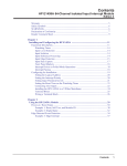
1-2. GENERAL INFORMATION
The seamless GRAPHIC SWITCHER II™ inserts (PIP), cuts, fades, wipes and instantaneously mixes (no glitch)
between 16 high-resolution and TV/Video sources which can range (Auto Sync and Auto Scan) from 15 kHz up to 130
kHz (up to 1600 x 1280), with no synchronization "dropouts".
The GRAPHIC SWITCHER II™ Up or Down scales each input to one user-programmable output format, matching
the native resolution of any projector (LCD, DLP or CRT), plasma display, video wall or multisync. monitor. All input
and output parameters and formats can be stored and saved as NON-volatile memory. In addition, several sequences
with users’ effects can be run automatically. An RS-232 Remote Control input is provided.
The GRAPHIC SWITCHER II™ ’s outputs are:
• 1 MAIN output “PROGRAM” (BNC + HD15).
• 1 PREVIEW output “PRESET” for visualization and adjustment before the switch.
• 4 TALLY outputs (that can be selected from any of the 16 inputs to indicate who is “ON AIR”).
• TV/VIDEO output (option).
The output format can be selected in HDTV, D-ILA, SXGA, XGA2, SVGA, or VGA and remains constant no matter
which input is selected. This allows for a "one time" adjustment of your display device.
The GRAPHIC SWITCHER II™ comes with a “natural color” Comb Filtering decoder with a robust sync. detection,
an enhanced 3D Auto Adaptive Motion Compensation video scaling process and a 3/2 pull down Film to video
correction (NTSC). This device takes the term “user friendly” to a new level. PIP (Picture in Picture), seamless fading
and effects combined with direct access auto-recognition inputs, makes live High End presentations better and easier
than before. It can be easily updated by software for new features.
For Multi-screen applications, 2 or 3 GRAPHIC SWITCHER II™’s can be “Stacked” together and controlled by only
one Remote Control Unit (RCU2811). Also available is an optional "Show Manager" software to control 1 to 16
devices with fully automated different sequences & input selection.
1-3. GRAPHIC SWITCHER II™ REFERENCES
REFERENCES
GSW2811R
GSW2811R-D1
OPT-GSW2-VO
ADD-ON-1
ADD-ON-2
DESIGNATIONS
GRAPHIC SWITCHER II™ (without option)
GRAPHIC SWITCHER II™ (with optional SDI input)
Optional video outputs (Composite video + S.VIDEO + YUV)
Optional upgrade for "Edge blending" application.
Optional upgrade for PIP, POP & TITLE switching.
1-4. GRAPHIC SWITCHER II™ OPTIONAL ACCESSORIES
REFERENCES
RCU2811
SWM2811
KSW2811
DESIGNATIONS
REMOTE CONTROL UNIT (allows to control up to 3 GSW2811R/GSE2811R)
SHOW MANAGER™ control software (allows to control up to 16 GSW2811R/GSE2811R)
KIT DOUBLER CONTROL FOR 3 GSW2811R/GSE2811R.
PAGE 5
GRAPHIC SWITCHER II™
Chapter 2 : INSTALLATION
IMPORTANT: Please read all of the safety instructions (pages 2 to 4) before starting.
• Table top mounting:
The GRAPHIC SWITCHER II™ can be used directly on a table: the unit is equipped with 4 plastic
feet.
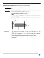
• Rack mounting:
The GRAPHIC SWITCHER II™ is compatible with a 19” enclosure. Please follow the instructions
below to install the GRAPHIC SWITCHER II™ in a 19” rack.
c Place the GRAPHIC SWITCHER II™ in your rack.
NOTE: Your rack must be equipped with some braces.
d Attach the GRAPHIC SWITCHER II™ to the rack by using 4 screws in the front panel holes
(screws are not included).
e Connect all of the cables of the GRAPHIC SWITCHER II™ and attach them to the rack with
some tie wraps.
IMPORTANT:
- The openings in the front and in the rear panels are for cooling. Do not cover these
openings.
- Be sure that no weight in excess of 2 kg (4.4 Lbs.) is added onto the GRAPHIC
SWITCHER II™.
- The maximum ambient operating temperature must not exceed 40 °C (104 °F).
- The rack and all mounted equipment in it must be reliably grounded to national and local
electrical codes.
PAGE 6
GRAPHIC SWITCHER II™
Chapter 3 : TECHNICAL DESCRIPTION
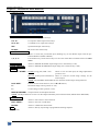
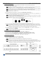
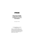
3-1. FRONT PANEL
INPUT SELECT (PROGRAM & PREVIEW)
1 to 8 :
8 RGB/YUV input selection keys.
9 to 16 :
8 Composite Video input selection keys.
S1 to S4 :
4 S.VIDEO (Y/C) input selection keys.
SDI :
Optional SDI input selection key.
BLACK :
BLACK screen selection key.
TRANSITION - EFFECTS
TAKE :
Allows to switch the pre-selected input (blinking key) on the MAIN output with the preselected EFFECT (EFFECT KEYS).
1, 2, 3, 4 :
Four EFFECT keys. Each of those keys can store one of the effects available in the LCD effect
menu.
FREEZE MAIN
Allows to FREEZE the MAIN output image (active when the key is ON).
FREEZE PREVIEW
Allows to FREEZE the PREVIEW output image (active when the key is ON).
ADJUST
RECALL / STORE : STORE (a long push, LED = ON):
allows to store for each input, the image adjustments
(position, size).
RECALL (a short push on the button): allows to recall the stored image settings for the
selected input.
NOTE: The GRAPHIC SWITCHER II™ has 40 NON-volatile image setting memories.
POS / SIZE :
Position or Size mode selection. (Acts on H & V buttons).
H:
Horizontal image control (position or size).
V:
Vertical image control (position or size).
MAIN & PREVIEW : Output selection for the adjust functions.
NOTE: The adjust functions are active on the output indicated by the turned ON LED's (MAIN and/or PREVIEW).
LCD WINDOWS
CONTROL Allows to select items in the LCD menu.
EXIT / MENU :
Allows to exit from a LCD menu.
ENTER :
Allows to validate the selected item.
STEP
(SEQUENCE)
Allows to directly step through a programmed switching sequence.
PAGE 7
Chapter 3 : TECHNICAL DESCRIPTION (continued)
GRAPHIC SWITCHER II™
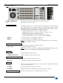
3-2. REAR PANEL
POWER CONNECTOR:
Standard IEC input connector (100-240 VAC, 50-60Hz automatic).
O/I:
Power switch (O = OFF, I = ON)
RGB / YUV INPUTS
1 to 8 :
8 x RGB/YUV inputs on 3, 4, or 5 BNC connectors. The RGB/YUV inputs can accept
both COMPUTER sources (RGBHV, RGBS, and RGsB (SOG) signals), standard
TV/VIDEO sources (YUV, RGBS (TTL), RGsB (SOG), and RGBS (analog) signals),
and HDTV SOURCES (720p & 1080i with bi-level sync only).
• RGB HV (Separate H & V Sync.) : on 5 BNC connectors.
• RGB S (Composite Sync.) : on 4 BNC connectors (R, G, B, C SYNC).
• RGsB (SOG) : on 3 BNC connectors (R, G, B).
• YUV (COMPONENT) : on 3 BNC connectors (R-Y, Y, B-Y).
• 720p & 1080i with bi-level sync : on 5 BNC connectors (RGBHV).
INPUT 2 :
2nd connector (HD 15 F) of the RGB/YUV INPUT 2.
INPUT 3 :
2nd connector (HD 15 F) of the RGB/YUV INPUT 3.
NOTE: For the INPUT #2 and #3, never connect simultaneously sources on the HD15
and on the BNC connectors.
REMOTE RS-232 & TALLY OUT
RS-232 :
Standard remote control RS-232 on DB9 F connector.
TALLY OUT :
OPTIONAL
SDI INPUT :
COMPOSITE OUTPUT :
4 tally outputs on DB9 F connector.
NOTE: This connector is also used for updating the GRAPHIC SWITCHER II™. (See
Chapter 8 : UPDATING THE GRAPHIC SWITCHER II™).
Optional SDI input on BNC connector.
Optional composite output on BNC connector.
COMPOSITE & S.VIDEO INPUTS
9 to 16 :
8 composite video inputs on BNC connectors.
S1 to S4 :
OUTPUTS
MAIN :
4 S.VIDEO (Y/C) inputs on 2 x BNC connectors.
MAIN output for the MAIN display device (video projector, PLASMA, data monitor)
on 3, 4, or 5 BNC connectors.
2nd MAIN :
Additional MAIN output on HD15 F connector.
PREVIEW :
PREVIEW output for the PREVIEW MONITOR, on HD 15 F connector.
OPTIONAL VIDEO OUTPUT
PAGE 8
Optional video output (YUV or S.VIDEO) on DB9 F connector.
GRAPHIC SWITCHER II™
Chapter 4 : STARTING
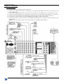
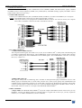
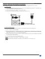
4-1. CONNECTIONS
c Turn OFF all of your equipment before connecting.
d Connect your computers (PC, MAC, workstation), your component and RGBS video sources to the inputs (1 to 8)
of the GSW2811R.
e Connect your COMPOSITE sources to the inputs (9 to 16) and/or your S.VIDEO sources to the inputs (S1 to S4).
f Connect your MAIN display device (data projector, plasma screen...) to the "MAIN" output (BNC (x5) connectors).
g Connect your control monitors to the PREVIEW output and to the 2nd MAIN output (HD15 connectors).
h Connect the AC power supply cord to the GRAPHIC SWITCHER II™ and to a power outlet.
i Turn ON the projector, the local monitors, the GRAPHIC SWITCHER II™ (rear panel switch) and then all of your
input sources.
NOTE: If the output image pixelize, switch OFF and ON the GRAPHIC SWITCHER II™.
PAGE 9
Chapter 4 : STARTING (continued)
GRAPHIC SWITCHER II™
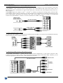
4-2. RGB/YUV INPUTS (1 to 8)
The RGB/YUV INPUTS can accept both COMPUTER sources (RGBHV, RGBS, and RGsB (SOG) signals), standard
TV/VIDEO sources (YUV(Component), RGBS (TTL), RGsB (SOG), and RGBS (analog) signals), and HDTV sources
(720p & 1080i with bi-level sync only).
c COMPUTER SOURCES:
Connect your COMPUTERS (PC, MAC, WORKSTATION) with BNC (x5) cables to the RGBHV (#1 to #8) inputs.
NOTE: • For RGBS signals connect the Sync cable to the H/C BNC connector.
• The Input #2 and #3, are equipped with an additional HD15 connector. You can also connect your computer
source either on the BNC connectors or either on the HD15 connector.
d TV/VIDEO SOURCES:
• COMPONENT VIDEO SIGNAL :
The Component Video signal, also called YUV (Y, R-Y, B-Y) or BETACAM™ is widely used in broadcasting and
is available on high-quality DVD players. The COMPONENT signal is transmitted with 3 coaxial cables, and also
has a better quality picture than COMPOSITE and S.VIDEO signals. The COMPONENT connectors are usually
RCA (x3), or BNC (x3).
• RGBS VIDEO SIGNAL:
This signal is widely used in broadcasting and is available on European DVD player and Satellite receivers. The
RGB.S signal is transmitted with 4 coaxial cables, and also has a better picture quality than COMPOSITE and
S.VIDEO signals. The RGB.S connectors are usually BNC connectors for Broadcasting equipment, and SCART
connector for DVD players and Satellite Receivers. Connect the RGBS VIDEO signal with BNC cables to the R, G,
B, H/C BNC connectors of the #1 to #8 inputs of the GRAPHIC SWITCHER II™.
e HDTV SOURCES:
• 720p & 1080i: The GRAPHIC SWITCHER II™ accepts the 720p & 1080i HDTV formats with bi-level sync only
(RGBHV). Connect your HDTV signal as a Computer signal. For signals with tri-level sync you may required an
interface (i.e.: TV-HDTV INTERFACE, reference: HDI100).
PAGE 10
GRAPHIC SWITCHER II™
Chapter 4 : STARTING (continued)
4-3. COMPOSITE INPUTS (9 to 16) & S.VIDEO INPUTS (S1 to S4):
The Composite Video signal, usually called COMPOSITE or VIDEO, is available on most video equipment (VCR, DVD,
CAMCORDER…), but is also the lowest in picture quality. The video standard of this signal can be NTSC, PAL or
SECAM. The signal is transmitted on a single coaxial cable, and is connected to the video equipment with an RCA or a
BNC connector.
The S.VIDEO signal, also called Y/C, HI-8™, or S.VHS™, is available on DVD players and high quality VCRs (S.VHS).
The S.VIDEO signal in which the Luminance (Y) and Chrominance (C) informations are separately transmitted (2 wires)
gives a higher quality picture than the Composite video signal. The S.VIDEO connector is usually a 4 pin Mini-DIN
connector also called Oshiden™ connector. It can also sometimes be on 2 BNC connectors.
4-4. MAIN AND PREVIEW OUTPUTS
The GRAPHIC SWITCHER II™ is equipped with 1 MAIN OUTPUT on BNC (x5) connectors for the DISPLAY DEVICE,
and two monitoring outputs on HD 15 connectors.
4-5. OPTIONAL VIDEO OUTPUT (OPT-GSW2-VO option)
The GRAPHIC SWITCHER II™ equipped with this option provides simultaneously 3 video signals (composite video,
S.VIDEO and YUV) in output. These 3 video outputs display the same image as the MAIN output. Therefore you can
record your presentation onto one or many video recorders of your choice.
PAGE 11
GRAPHIC SWITCHER II™
Chapter 5 : OPERATING MODE
5-1. SETTINGS
c We recommend resetting the GRAPHIC SWITCHER II™ to all of its default values, with the LCD screen (control
menu > default value > yes) before proceeding. Then switch OFF and ON the device.
d Select the type of signal connected to the RGB/YUV inputs (input menu > RGB/YUV inputs >...).
e Select the Output sync. type which correspond to your display device (outputs menu > output sync >...).
f Select the Output rate mode (outputs menu > output rate >...). Please see the Output rate mode table below.
g Select an Output format (outputs menu > output format >...).
NOTE: For fixed pixels display device (DMD, LCD, PLASMA…), always select the output format corresponding to
the native resolution of your display device. Thus, the display device will not have to scale the image and the
result will be better.
h Select the Type of screen corresponding to your wall mounted projection screen shape (outputs menu > type of
screen > 4/3 or 16/9).
i Select the COMPOSITE & S.VIDEO mode corresponding to your configuration (input menu > CV/SV mode>...).
j Disable the unused input KEYs with the LCD screen (input menu > used inputs >...).
• Light OFF = disabled input.
• Light ON = selected input.
• Low light = not selected input.
• Blinking light = pre-selected input.
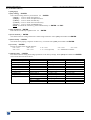
MODES
APPLICATIONS
OUTPUT RATE
OUTPUT
FORMAT.
OUTPUT RATE MODE TABLE
Output rate = "input #" rate
Output rate = internal rate
Movie and motion pictures display.
Video presentation (static pictures).
Locked on the Frame Rate of the video input
Generated by the GRAPHIC SWITCHER II™
(60 Hz or 75 Hz)
selected in the "Output rate" menu (menu # 2-2)
(50 Hz if PAL or SECAM and 59.94 Hz if NTSC)
• 640 x 480 L
• VGA 60 Hz
• VGA 75 Hz
• 800 x 600 L
• SVGA 60 Hz
• SVGA 75 Hz
• 1024 x 768 L
• XGA 60 Hz
• XGA 75 Hz
• 1280 x 1024 L
• SXGA 60 Hz
• 1365 x 1024 L
• D-ILA 4/3
• 1365 x 768 L
• D-ILA 16/9
• HDTV 480p
• HDTV 480p
• HDTV 720p
• HDTV 720p
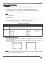
5-2. DISPLAY DEVICES ADJUSTMENTS
c Set the MAIN test pattern on the "ON" position (outputs menu > test pattern > main > on). Four corner shapes
appear on the MAIN displays.
d Adjust directly the display device itself, using its H and V size and position control parameter to fill the four corner
shapes in the full screen.
e Renew the same process to adjust your PREVIEW display device.
NOTE: Now the display devices are identically adjusted, you can also make the image adjustments on the display
device of your choice. When you are in a live display, you can make corrections on the PREVIEW monitor
only, without disturbing the MAIN display device.
PAGE 12
GRAPHIC SWITCHER II™
Chapter 5 : OPERATING MODE (continued)
5-3. IMAGE ADJUSTMENTS
For each input source connected to the GRAPHIC SWITCHER II™, make the following adjustments:
c Select the source you want to adjust.
NOTE: To adjust your source on your PREVIEW monitor : you just have to press on the corresponding INPUT
SELECT key. The key is blinking and the source is displayed on the PREVIEW monitor.
NOTE: To adjust your source on your MAIN display device : press on the corresponding key (the key is blinking)
and press TAKE (the key is ON and the source is displayed on the MAIN display device).
NOTE: If the Pattern is well adjusted on both PREVIEW and MAIN , then the input adjustment can be made on
the PREVIEW or MAIN as well.
d Select the aspect ratio (4/3, letterbox...) of your source (image menu > aspect ratio >...).
e Adjust the vertical and horizontal position (with the front panel "H & V" adjust buttons). The adjustments are
visible on the selected output and their values are displayed in the LCD screen.
NOTE: The MAIN and PREVIEW LED'S indicate on which output the adjustment will be performed. To change
the output, presses on the MAIN/PREVIEW button.
NOTE: To adjust the SIZE, presses the POS/SIZE button and adjust with the "H & V" adjust buttons. The selected
mode (POS or SIZE) is displayed on the LCD screen.
f Press on the STORE button for 2 seconds until the LED flashes once to memorize the position & size adjustments.
NOTE: The GRAPHIC SWITCHER II™ is provided with 40 NON-volatile image memories. Each of these
memories contains the input channel number, the input and output format parameters and all of the image
adjustments. When the 40 memories are used, each new memorization erases the oldest memory.
g If needed, make the others adjustments, available in the LCD image menu (color, brightness, image process…).
Validate each adjustment with ENTER.
NOTE: To erase the image adjustments, use the Preset function (image menu > preset).
5-4. OPTIONAL VIDEO OUTPUT ADJUSTMENT
c
d
e
f
Select the video "output rate" (outputs menu > video output > output rate >...).
Select the output standard (outputs menu > video output > video standard > NTSC or PAL).
Select the zoom mode (outputs menu > video output > U/Over scan > underscan or overscan).
Select a level of anti-flicker (outputs menu > video output > flicker adj. >...).
5-5. SWITCHING OPERATION
c Pre-select an input on the input select bus (KEY blinking).
d Select a TRANSITION effect on the 1 to 4 EFFECTS keys.
NOTE: The effect stored in the selected EFFECT key is displayed on the LCD screen.
e Press on TAKE. The pre-selected input is displayed on the MAIN output with the selected effect transition.
NOTE: According to the selected effect the TAKE key may turn ON or blink during the transition. When the
TAKE key is turned ON you should wait for the end of the transition before doing another selection. When
the TAKE key is blinking, then you should press the TAKE key to stop the transition.
PAGE 13
Chapter 5 : OPERATING MODE (continued)
GRAPHIC SWITCHER II™
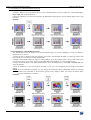
5-6. EXAMPLES OF TRANSITIONS & EFFECTS
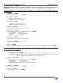
c WIPE TRANSITION:
• Assign a WIPE to one of the EFFECTS keys: Press one EFFECTS key, select a WIPE (for example: hor wipe >
left to right) then select the duration.
• Press the TAKE key to activate the transition: the PREVIEW image appears onto the MAIN display with a wipe
transition.
Example:
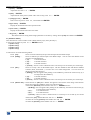
d TITLE EFFECT (OR SHADOW TITLE):
The TITLE effect allows to display a text onto the MAIN image. For a better readability you also can display a
shadow bar onto your text.
• Create the text to displayed with the computer connected to the GSW2811R thanks to a drawing software like
Power Point (text in white onto a black background).
• Display on the MAIN output the source to titling (INPUT #2 in the example below), then pre-select the source
used for create the text: the image appears on the PREVIEW output (INPUT #1 in the example below).
• Assign the TITLE effect to one of the EFFECTS keys: Press one EFFECTS key, select title or shadow title, then
select the duration.
• Press the TAKE key to activate the effect (ACTION 1): the text is now displayed onto the image of the MAIN
output.
NOTE: With the ADD-ON-2 upgrade, you can change the background image (PREVIEW image) by selecting
another input (ACTION 2): the transition operates with a fading to black. To remove the TITLE effect,
press the TAKE key (ACTION 3).
Example:
PAGE 14
GRAPHIC SWITCHER II™
Chapter 5 : OPERATING MODE (continued)
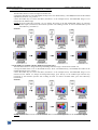
5-6. EXAMPLES OF TRANSITIONS & EFFECTS (continued)
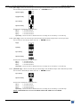
e PIP EFFECT:
The PIP effect allows to insert an image into another one.
• Assign the PIP effect to one of the EFFECTS keys: Press one EFFECTS key, select PIP, then make all the needed
adjustments (duration, size, position...).
• Press the TAKE key to activate the effect (ACTION 1 in the example below): the PREVIEW image is now
inserted into the MAIN image.
NOTE: With the ADD-ON-2 upgrade, you can change the image in the PIP (PREVIEW image) by selecting
another input (ACTION 2): the transition operates with a fading to black. To remove the PIP effect, press
the TAKE key (ACTION 3).
Example:
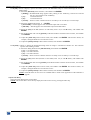
f POP EFFECT (available with the ADD-ON-2 upgrade only):
The POP effect allows to change the background image when an image is inserted into another one.
• Assign the POP effect to one of the EFFECTS keys: Press one EFFECTS key, select POP, then make all the
needed adjustments (size, position...).
• Press the TAKE key to activate the effect (ACTION 1 in the example below): the PREVIEW image is now
inserted into the MAIN. To change the background image, press directly on the needed input selection key
(ACTION 2): the transition operates with a fading to black. To remove the POP effect, press the TAKE key
(ACTION 3).
Example:
NOTE: The POP effect can not be use as extended effect in multi-screen application of the ADD-ON-1 upgrade.
PAGE 15
GRAPHIC SWITCHER II™
Chapter 6 : LCD SCREEN DESCRIPTION
6-1. INTRODUCTION
The LCD screen is composed of 2 modes: the STATUS MODE and the CONTROL MODE.
• The STATUS MODE indicates the input and the output status of the GRAPHIC SWITCHER II™.
• The CONTROL MODE allows selecting and adjusting the parameters of the GRAPHIC SWITCHER II™.
6-2. LCD CONTROL BUTTONS
The LCD screen is controlled by 3 buttons :
CONTROL knob: To scroll thru the different menus.
EXIT MENU button:
• From the STATUS MODE, press on this button to display the CONTROL MODE.
• From the CONTROL MODE, press on this button to:
- return to the previous menu,
- return to the STATUS MODE (press several times),
- return without safeguarding the item.
ENTER button :
• From the STATUS MODE, press on this button to return to the previous consulted menu.
• From the CONTROL MODE, press on this button to confirm a selected item.
NOTE: When entering in the CONTROL MODE, the LCD window will automatically display the STATUS MODE
after 60 seconds of inactivity of the front panel buttons.
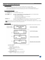
6-3. STATUS MODE
When switching the GRAPHIC SWITCHER II™ ON, the LCD screen displays the product's name and status as follows:
c OUTPUT FORMAT
d OUTPUT RATE
• [internal rate] or [input # rate].
• [60Hz] = output frame frequency.
e SELECTED INPUT
• [MAIN = 3] = number of the selected input.
• [XGA] = input format.
• [48.6K/60Hz] = line frequency / frame frequency.
f PRE-SELECTED INPUT
• [PREV = 5] = number of the pre selected input.
PAGE 16
GRAPHIC SWITCHER II™
Chapter 6 : LCD SCREEN DESCRIPTION (continued)
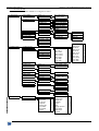
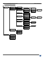
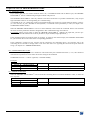
6-4. CONTROL MODE
The menus of the CONTROL MODE are configured as follow :
1 input menu
1 input status
main = xx
prev = xx
The LCD displays
the video status
2 RGB/YUV inputs
1 RGB/YUV 1
2 RGB/YUV 2
3 RGB/YUV 3
4 RGB/YUV 4
…..
9 all RGB/YUV
1 SDTV YUV
2 SDTV RGBS TTL
3 SDTV RGB SOG
4 SDTV RGBS ana.
5 Computer SOG
6 Computer HV/C.
7 HDTV
3 video standard
auto
manual
1 composite 9
2 composite 10
…..
12 s.video S4
4 used inputs
5 H sync load
6 CV/SV mode
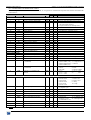
2 outputs menu
1
2
3
4
5
8 CV
6 CV + 1 SV
4 CV + 2 SV
2 CV + 3 SV
4 SV
1 output format
2 output rate
3 rate status
4 output sync
640 x 480 L
800 x 600 L
1024 x 768 L
1280 x 1024 L
1365 x 1024 L
1365 x768 L
HDTV 480p
HDTV 720p
1 internal rate
2 RGB/YUV1 rate
3 Compos. 9 rate
4 S.VIDEO 1 rate
5 SDI rate
main = xx
prev = xx
5 type of screen
screen 4/3
screen 16/9
6 tally
7 tally status
8 test pattern
tally selection
9 video output
1 video standard
1 NTSC
2 PAL
2 output rate
1 internal
2 follow
3 genlock
3 flicker adj.
0
4 U/Over scan
1 Over scan
2 Under scan
11 RGB levels
main = xx
prev = xx
R
A
T
E
V
I
D
E
O
I
N
P
U
T
I
N
T
E
R
N
A
L
R
A
T
E
input selection
test pattern
off
on
main = xx
prev = xx
1 black level
2 H smooth
3 V smooth
4 optimize
5 aspect ratio
6 pos status
7 size status
8 preset
I
N
P
U
T
VGA 60 Hz
SVGA 60 Hz
XGA 60 Hz
SXGA 60 Hz
VGA 75 Hz
SVGA 75 Hz
XGA 75 Hz
D-ILA (4/3)
D-ILA (16/9)
HDTV 480p
HDTV 720p
H&V COMP SOG
H&V COMP
10 soft-edge
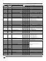
3 image menu
1 auto
2 NTSC
3 PAL
4 SECAM
5 black&white
C
O
M
P
U
T
E
R
I
N
P
U
T
1
2
1 U/overscan
2 aspect ratio
3 brightness
4 contrast
5 color
6 hue
7 image process
8 pos status
9 size status
10 preset
PAGE 17
Chapter 6 : LCD SCREEN DESCRIPTION (continued)
GRAPHIC SWITCHER II™
6-4. CONTROL MODE (continued)
4 effects menu
1 effect
2 effect
3 effect
4 effect
1 key
2 key
3 key
4 key
1 cut
2 fading
3 title
4 shadow title
PAGE 18
1 languages
2 key locking
3 key brightness
4 erase all mem
5 demo mode
6 versions
7 default value
1 duration
2 size
3 position
4 intensity
holding
3s
5s
custom
effect duration
======= xxs
effect duration
1s 3s 5s custom
effect duration
======= xxs
1 left to right
2 right to left
3 to center
4 from center
6 vert wipe
1 up
2 down
3 to center
4 from center
7 diamond wipe
1 to center
2 from center
8 PIP
1 duration
2 type
3 size
4 position
5 mask size
6 mask position
5 current effect
5 control menu
effect duration
======= xxs
5 hor wipe
9 POP
6 sequence mode
1s 3s 5s custom
1 list sequence
2 play sequence
3 add step
4 erase last
5 clear sequence
1 fading time
2 size
3 position
4 mask size
5 mask position
1 Normal PIP
2 Fade PIP
1s 3s 5s custom
GRAPHIC SWITCHER II™
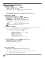
Chapter 7 : LCD FUNCTIONS DESCRIPTION
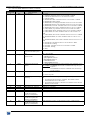
1[INPUT MENU] + ENTER.
1-1[Input Status] + ENTER.
Select [MAIN = x] or [PREV = x] with + ENTER.
• [MAIN = x] = Number of the selected input.
• [SYNC = xxxx] = Sync. type: [H+V+] = Separate H & V Sync. with polarities.
[COMP] = Composite Sync.
[SOG] = Sync. On Green.
• [XGA 48KHz/60Hz] = Name of the format, line / frame frequency [kHz/Hz], [i] = interlaced format.
• [NO INPUT] = No signal detected on this input.
• [OUT OF RANGE] = The input signal is not compatible with the input range of the device.
1-2[RGB/YUV inputs] + ENTER.
c Select first the RGB/YUV inputs with + ENTER.
d Then select the signal connected to the input with + ENTER between:
• [SDTV YUV] =
Component (YUV) video signal.
• [SDTV RGBS TTL] = RGB/S video signal with TTL Composite Sync.
• [SDTV RGB SOG] = RGsB video signal with analog Composite Sync. On Green.
• [SDTV RGBS ana.] = RGB/S with an analog Composite Sync. (0.3 Vp/p).
• [Computer SOG] =
RGsB Computer signal (Sync. on Green).
• [Computer HV/C.] = RGBHV or RGBS Computer signals.
• [HDTV] =
720p & 1080i with bi-level sync only (RGBHV).
NOTE : SDTV means Standard Definition TV (15 kHz).
1-3[Video standard] + ENTER.
Select an item with + ENTER.
• [auto] =
Automatic recognition of the video standard for all inputs. NTSC / PAL / SECAM / Black & White
are detected automatically; if not, please use the [manual] setting.
• [manual] = Manual selection of the video standard for each input.
c Select first an input with + ENTER.
d Then select the video standard with + ENTER.
• [auto] = Automatic detection.
• [NTSC] = NTSC detection only.
• [PAL] = PAL detection only.
• [SECAM] = SECAM detection only.
• [Black & White] = Black and White detection only.
1-4[Used inputs] + ENTER.
This function allows to disable the unused input keys.
Select an input [#1, to SDI] with and press ENTER to change the selection.
• [#1 used] = Input #1 used (KEY 1 is low lighted).
• [#6 unused] = Input #6 unused (KEY 6 is OFF).
1-5[H sync load] + ENTER.
Select [#1, #2, #3...] with and press ENTER to change the selection.
• [#1 75Ω load] = The H Sync. of the input #1 is set under 75 ohms.
• [#2 Hi-Z] = The H sync. of the input #2 is set under high impedance.
1-6[CV/SV mode] + ENTER.
Select the COMPOSITE & S.VIDEO mode corresponding to your configuration.
• [8 CV
] = 8 COMPOSITE inputs (# 9 to 16) are enabled.
• [6 CV + 1 SV] = 6 COMPOSITE inputs (# 9 to 14) and 1 S.VIDEO inputs (# S1) are enabled.
• [4 CV + 2 SV] = 4 COMPOSITE inputs (# 9 to 12) and 2 S.VIDEO inputs (# S1 & S2) are enabled.
• [2 CV + 3 SV] = 2 COMPOSITE inputs (# 9 & 10) and 3 S.VIDEO inputs (# S1 to S3) are enabled.
•[
4 SV] = 4 S.VIDEO inputs (# S1 to S4) are enabled.
PAGE 19
Chapter 7 : LCD FUNCTIONS DESCRIPTION (continued)
GRAPHIC SWITCHER II™
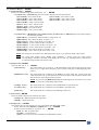
2[OUTPUT MENU] + ENTER.
2-1[output format] + ENTER.
Select one of the following output format with + ENTER.
• If [output rate] = [internal rate], the LCD window displays the following formats :
• [VGA 60 Hz] = 640 x 480 at 60 Hz
• [VGA 75 Hz] = 640 x 480 at 75 Hz.
• [SVGA 60 Hz] = 800 x 600 at 60 Hz
• [SVGA 75 Hz] = 800 x 600 at 75 Hz.
• [XGA 60 Hz] = 1024 x 768 at 60 Hz
• [XGA 75 Hz] = 1024 x 768 at 75 Hz.
• [SXGA 60 Hz] = 1280 x 1024 at 60 Hz.
• [D-ILA - 4/3] = 1365 x 1024 at 75 Hz.
• [D-ILA - 16/9] = 1365 x 768 at 75 Hz.
• [HDTV 480p] = 853 x 480 at 60 Hz.
• [HDTV 720p] = 1280 x 720 at 60 Hz.
• If [output rate] = [RGB/YUV1 rate], [compos.9 rate], [s.video1 rate], or [SDI rate] the LCD window displays
the following formats:
• [640 x 480 L] = Line doubler: 480p/59.94 Hz or 576p/50 Hz - 4/3.
• [800 x 600 L] = 800 x 600 at 50 Hz or 59.94 Hz - 4/3.
• [1024 x 768 L] = 1024 x 768 at 50 Hz or 59.94 Hz - 4/3.
• [1280 x 1024 L] = 1280 x 1024 at 50 Hz or 59.94 Hz.
• [1365 x 1024 L] = 1365 x 1024 at 50 Hz or 59.94 Hz - 4/3.
• [1365 x 768 L] = 1365 x 768 at 50 Hz or 59.94 Hz - 16/9.
• [HDTV 480p] = 853 x 480 at 50 Hz or 59.94 Hz - 16/9.
• [HDTV720p] = 1280 x 720 at 50 Hz or 59.94 Hz - 16/9.
NOTE: The output rate is 50 Hz for PAL & SECAM video inputs, or 59.94 Hz for NTSC video inputs.
NOTE: For fixed pixels display device (DMD, LCD, PLASMA…), always select the output format
corresponding to the native resolution of the display device. This way, the display device will not have
to scale the image and the result will be better.
2-2[output rate] + ENTER.
Select an item with + ENTER.
• [internal rate] =
The output frame rate is 60 Hz or 75 Hz depending of the selected output format (LCD
menu # 2-1). A higher frame frequency gives a better visual aspect when displaying static
pictures.
• [RGB/YUV1 rate] = The output frame rate is identical to the RGB/YUV1 input frame rate : 50 Hz if the input
video standard is PAL or SECAM and 59.94 Hz if the input video standard is NTSC. This
function allows improving the motion pictures.
NOTE: If you select the [RGB/YUV1 rate] the LCD display the LCD menu #1-2. Verify
or select the corresponding input format.
• [compos. 9 rate] =
The output frame rate is identical to the COMPOSITE 9 input frame rate.
• [s.video 1 rate] =
The output frame rate is identical to the S.VIDEO 1 input frame rate.
• [SDI rate] =
The output frame rate is identical to the SDI input frame rate.
2-3[rate status] + ENTER.
The LCD window displays the reference rate status.
• [compos. 9] = Referenced input for output rate.
• [50 Hz] = Output frame rate.
2-4[output sync] + ENTER
This function allows selecting the sync type of the MAIN and PREVIEW outputs.
c First select the output [MAIN] or [PREV] with + ENTER.
d Then select the output Sync. type with + ENTER.
• [H & V] = H & V separate Sync.
• [COMP] = Composite Sync.
• [SOG] = Sync. On Green (not available for the PREVIEW output).
PAGE 20
GRAPHIC SWITCHER II™
Chapter 7 : LCD FUNCTIONS DESCRIPTION (continued)
2-5[type of screen] + ENTER.
Select an item with + ENTER.
• [screen 4/3] = if your image is displayed on a 4/3 wall mounted projection screen shape.
• [screen 16/9] = if your image is displayed on a 16/9 wall mounted projection screen shape.
2-6[tally] + ENTER.
c First select a tally output with + ENTER between:
d Then select an input for this tally output with + ENTER.
2-7[tally status] + ENTER.
The LCD window displays the status of the selected tally output. Select a tally output with .
• [ON] = the tally output is active.
• [OFF] = the tally output is inactive.
2-8[test pattern] + ENTER.
This function allows displaying a test pattern for position and size adjustments.
c Select first the output [MAIN] or [PREV] with + ENTER.
d Then select one of the following functions with + ENTER.
• [ON] = Displays a test pattern on the selected output.
• [OFF] = Turns OFF the test pattern.
2-9[video output] + ENTER. (THIS MENU IS ONLY AVAILABLE WITH THE OPTIONAL VIDEO OUTPUT).
NOTE: The following functions act on the video outputs only (COMPOSITE VIDEO, S.VIDEO and COMPONENT).
2-9-1 [video standard] + ENTER.
Select the output standard for the video outputs with + ENTER between:
• [NTSC]
• [PAL]
2-9-2 [output rate] + ENTER.
Select a function with + ENTER between:
• [internal] = the video output is generated by the device (The output standard can be PAL or NTSC
depending on the LCD menu #2-9-1).
• [follow] =
the video output is synchronized onto the referenced input (Only if LCD menu # 2-2 is not
[internal rate]. The video output standard can be PAL or NTSC depending on the standard of
the referenced input).
• [genlock] = the video output is synchronized onto an external device. For this function you must:
- Connect the supplied video cable to the DB9 connector (OPTIONAL VIDEO OUTPUT).
- Connect the reference signal device to the "genlock input" yellow cable (BNC connector).
2-9-3 [flicker adj.] + ENTER.
Select a level of anti-flicker with + ENTER.
2-9-4 [U/Over scan] + ENTER.
Select the zoom mode with + ENTER between:
• [underscan] = Underscan mode. The entire image is visible on the screen. Computer display mode is
underscan.
• [overscan] = Overscan mode. The image is displayed about 8 % bigger than in underscan mode, to avoid
seeing the corners and the borders. Standard TV display mode is overscan.
2-10 [soft-edge] + ENTER. (THIS MENU IS ONLY AVAILABLE WITH THE ADD-ON-1 UPGRADE).
2-11 [RGB levels] + ENTER.
This function allows to a adjust the RGB levels of the outputs. Select a color with + ENTER and adjust the
level with + ENTER.
PAGE 21
Chapter 7 : LCD FUNCTIONS DESCRIPTION (continued)
GRAPHIC SWITCHER II™
3[IMAGE MENU] + ENTER.
NOTE: The IMAGE adjustments act on the selected and/or the pre-selected input. Select [MAIN] to adjust the image
displayed on the MAIN output and select [PREV] to adjust the image displayed on the PREVIEW output.
• If the selected input is a COMPUTER signal (LCD menu # 1-2 = Computer---) the IMAGE MENU displays the
following items :
3-1[Black level] + ENTER.
Adjust the black level with + ENTER.
3-2[H. smooth] + ENTER.
• [ON] = Vertical smoothing active.
• [OFF] = Vertical smoothing inactive.
3-3[V. smooth] + ENTER.
• [ON] = Horizontal smoothing active.
• [OFF] = Horizontal smoothing inactive.
3-4[optimize] + ENTER.
[#3 optimize] = Optimization of the input #3 image.
3-5[aspect ratio] + ENTER.
Select the Aspect Ratio of your input source with + ENTER.
• [4/3 standard] = 4/3 input format.
• [letterbox] =
Letterbox input format.
• [16/9] =
16/9 input format.
3-6[pos status] + ENTER.
Display the horizontal and vertical position status.
3-7[size status] + ENTER.
Display the horizontal and vertical size status.
3-8[preset] + ENTER.
This function allows setting all the image parameters to the factory settings. Select [YES] and validate with ENTER.
• If the selected input is a VIDEO signal (COMPOSITE, S.VIDEO, COMPONENT, RGsB or RGBS) the IMAGE
MENU display the following items :
3-1[U / Overscan] + ENTER.
Select an item with + ENTER.
• [underscan] = Underscan mode. The entire image is visible on the screen. Computer display mode is underscan.
• [overscan] = Overscan mode. The image is displayed about 8 % bigger than in underscan mode, to avoid seeing
the corners and the borders. Standard TV display mode is overscan.
3-2[aspect ratio] + ENTER.
Select the Aspect Ratio of your input source with + ENTER.
• [4/3 standard] =
4/3 input format.
• [letterbox] =
Letterbox input format.
• [WS anamorphic] = Wide Screen anamorphic input format.
3-3[brightness] + ENTER.
Adjust the brightness with + ENTER.
3-4[contrast] + ENTER.
Adjust the contrast with + ENTER.
PAGE 22
GRAPHIC SWITCHER II™
Chapter 7 : LCD FUNCTIONS DESCRIPTION (continued)
3-5[color] + ENTER
Adjust the color with + ENTER.
3-6[hue] + ENTER.
Adjust the tint of the picture (NTSC video sources only) with + ENTER.
3-7[image process] + ENTER.
Select a level of process with , and validate with ENTER.
3-8[pos status] + ENTER.
Display the horizontal and vertical position status.
3-9[size status] + ENTER.
Display the horizontal and vertical size status.
3-10 [preset] + ENTER.
This function allows setting all the image parameters to the factory settings. Select [YES] and validate with ENTER.
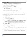
4[EFFECT MENU]
This menu allows to store an effect in the 4 Effect memory keys (front panel keys).
c First select an effect key with + ENTER between:
4-1[effect 1 key]
4-2[effect 2 key]
4-3[effect 3 key]
4-4[effect 4 key]
d Then select one of the following effects:
4-x-1 [cut] =
allows to switch seamlessly the pre-selected input onto the MAIN output.
4-x-2 [fading] =
allows to fade the pre-selected input to the MAIN output . You can select the duration of the
transition as indicated below :
• [1s] =
1 second transition.
• [3s] =
3 seconds transition.
• [5s] =
5 seconds transition.
• [custom] = allows to select a duration from 0.5 second up to 25 seconds by 0.5 second steps.
4-x-3 [title] =
allows to overlay a title on the MAIN output . The title should be done with drawn standard
software (Paint, PowerPoint...) in white color on a black background . You can select the
duration of this effect between:
• [holding] = the text appears after pushing on the TAKE key, and will be removed only by a
second push on the TAKE key.
• [3s] =
3 seconds transition.
• [5s] =
5 seconds transition.
• [custom] = allows to select a duration from 0.5 second up to 25 seconds by 0.5 second steps.
4-x-4 [shadow title] = Same function as [title] but a shadow bar appears at the bottom of the image. This function
allows increasing the readability of the text on bright images.
c Select the [duration] of the transition with + ENTER between :
• [holding] = the text appears after pushing on the TAKE key, and will be removed only by
a second push on the TAKE key.
• [3s] =
3 seconds transition.
• [5s] =
5 seconds transition.
• [custom] = allows to select a duration from 0.5 second up to 25 seconds by 0.5 second
steps.
d Select the [size] of the shadow bar with + ENTER.
e Select the vertical [position] of the shadow bar with + ENTER.
f Select the [intensity] of the shadow with + ENTER.
PAGE 23
Chapter 7 : LCD FUNCTIONS DESCRIPTION (continued)
GRAPHIC SWITCHER II™
4-x-5 [hor. wipe] = allows to switch the pre-selected input onto the MAIN output with a horizontal wipe effect.
c First select an horizontal wipe effect with + ENTER between:
• [left to right]
• [right to left]
• [to center]
• [from center]
d Then select the duration of the transition.
• [1s] =
1 second transition.
• [3s] =
3 seconds transition.
• [5s] =
5 seconds transition.
• [custom] = allows to select a duration from 0.5 second up to 25 seconds by 0.5 second step.
4-x-6 [vert wipe] = allows to switch the pre-selected input onto the MAIN output with a vertical wipe effect.
c First select an vertical wipe effect with + ENTER between:
• [up]
• [down]
• [to center]
• [from center]
d Then select the duration of the transition.
• [1s] =
1 second transition.
• [3s] =
3 seconds transition.
• [5s] =
5 seconds transition.
• [custom] = allows to select a duration from 0.5 second up to 25 seconds by 0.5 second step.
4-x-7 [diamond wipe] = allows to switch the pre-selected input onto the MAIN output with a diamond wipe effect.
c First select a diamond wipe effect with + ENTER between:
• [to center]
• [from center]
d Then select the duration of the transition.
• [1s] =
1 second transition.
• [3s] =
3 seconds transition.
• [5s] =
5 seconds transition.
• [custom] = allows to select a duration from 0.5 second up to 25 seconds by 0.5 second steps.
NOTE: THIS EFFECT IS NOT AVAILABLE WITH THE ADD-ON-1 UPGRADE.
PAGE 24
GRAPHIC SWITCHER II™
Chapter 7 : LCD FUNCTIONS DESCRIPTION (continued)
4-x-8 [PIP] = allows to display a picture into another picture. The PREVIEW image is reduced and displayed onto the
MAIN image.
c Select the [duration] of the transition , and validate with ENTER.
• [holding] = the PREVIEW image appears after pushing on the TAKE key, and will be removed
only by a second push on the TAKE key.
• [3s] =
3 seconds transition.
• [5s] =
5 seconds transition.
• [custom] = allows to select a duration from 0.5 second up to 25 seconds by 0.5 second steps.
d Select the [type] of PIP with + ENTER.
• [normal PIP] = The PIP appears onto the MAIN output with a cut effect.
• [fade PIP] = The PIP appears onto the MAIN output with a fade effect.
e Select the [size] of the PIP (between 15 and 100%) with (or with H and V), and validate with
ENTER.
f Set the horizontal and vertical [position] of the PIP windows with the H and V knobs, and validate
with ENTER.
g Adjust the [mask size] with H and V knobs, and validate with ENTER. This function allows, for
example, cutting the black bars of a letterbox source.
h Adjust the [mask position] with the H and V knobs, and validate with ENTER.
4-x-9 [POP] = allows to change the background image when an image is inserted into another one. The transition
operates with a fading to black.
c Select the fading duration with [fade duration], and validate with ENTER.
• [1s] = 1 second transition.
• [3s] = 3 seconds transition.
• [5s] = 5 seconds transition.
• [custom] = allows to select a duration from 0.5 second up to 25 seconds by 0.5 second steps.
d Select the [size] of the POP (between 15 and 100%) with (or with H and V), and validate with
ENTER.
e Set the horizontal and vertical [position] of the POP windows with the H and V knobs, and validate
with ENTER.
f Adjust the [mask size] with H and V knobs, and validate with ENTER. This function allows, for
example, cutting the black bars of a letterbox source.
g Adjust the [mask position] with the H and V knobs, and validate with ENTER.
NOTE: The POP effect can not be use as extended effect in multi-screen application of the ADD-ON-1
upgrade.
4-5[current effect]
The LCD screen displays the current effect.
NOTE: The current effect can be directly displayed on the LCD screen by pressing the effect key.
PAGE 25
Chapter 7 : LCD FUNCTIONS DESCRIPTION (continued)
GRAPHIC SWITCHER II™
4-6[sequence mode] + ENTER.
This mode allows programming a sequence of transition. The sequence can also be activated at any time during the
show, and controlled step by step (one step = pre-selection + transition) by one key only: the STEP key. This function
allows to simplify the use of the device during a show.
4-6-1 [list sequence] + ENTER.
This function allows to verify the programmed sequence. Turn the knob to display the list.
4-6-2 [play sequence] + ENTER.
This function allows to start or stop the programmed sequence.
IMPORTANT: Before starting, verify that the correct input is displayed onto the MAIN output.
c Select start with and press ENTER to start the programmed sequence. The STEP key is blinking and
the first pre-selected source is displayed onto the PREVIEW output. Press the STEP key to execute the first
transition and pre-select the next source and so on.
NOTE: For holding effect (i.e. : holding PIP): the first push on STEP allows to activate the effect and a
second push on STEP stops the effect.
d To stop the sequence press ENTER, the LCD menu displays [play sequence]: select stop with and
validate with ENTER. The STEP key turns OFF.
4-6-3 [add step] + ENTER.
This function allows to add a step into your sequence. A step is composed of an input pre-selection and a
transition. Each new step is added at the end of your sequence.
Proceed as follow:
c Select start and validate with ENTER. The STEP key turns ON.
d Pre-select an input with the input selection keys (the key is blinking and the image appears onto the
PREVIEW output).
e Select a transition: Press one of the four effect keys (1, 2, 3, 4) and select the needed effect.
f Press on STEP to add this new STEP into your sequence. The transition is displayed onto the MAIN output.
NOTE: For holding effect (i.e. : holding PIP): the first push on STEP allows to activate the effect and a
second push on STEP to stops the effect.
g Repeat the operations d, e, f to add any new steps.
NOTE: You can add up to 40 STEPS into your sequence.
h Select stop to deactivate the add step function. The STEP key turns OFF.
4-6-4 [erase last] + ENTER.
Erases the last step of the sequence.
4-6-5 [clear sequence] + ENTER.
Erases all of the sequence.
PAGE 26
GRAPHIC SWITCHER II™
Chapter 7 : LCD FUNCTIONS DESCRIPTION (continued)
5[CONTROL MENU]
5-1[languages]
5-2[key locking] + ENTER.
Select which locking function you need with + ENTER.
• [input] = Lock or unlock the input keys.
• [adjust] = Lock or unlock the adjust functions.
• [effects] = Lock or unlock the effect key.
• [control] = Lock or unlock the LCD control key.
• [freeze] = Lock or unlock the FREEZE keys.
NOTE: To unlock the control key, pushes simultaneously on ENTER and EXIT.
5-3[key brightness] + ENTER.
Select the level of the key brightness with + ENTER.
5-4[erase all mem] + ENTER.
This function allows erasing all the NON-volatile image memories. Select [YES] and validate with ENTER.
5-5[demo mode] + ENTER.
This mode allows playing a sequence of effect every 4 seconds. Select [YES] and validate with ENTER.
5-6[versions] + ENTER.
Display the status of the internal firmware.
• A = xxxx
• B = xxxx
• D = xxxx
• K = xxxx
• X = xxxx
• V = xxxx (optional)
• Y = xxxx
• S = xxxx
• I = Identification number.
5-7[default value] + ENTER.
This function allows setting all the image parameters to the factory settings. Select [YES] and validate with ENTER.
Then switch OFF and ON the device.
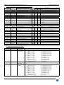
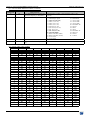
FUNCTION
1-2 RGB/YUV inputs
1-3 video standard
1-4 used Inputs
1-5 H Sync Load
1-6 CV/SV mode
2-1 output format
2-2 output rate
2-4 output sync
2-5 type of screen
2-6 tally
POSITION
computer HV/C
auto
used
Hi-Z
4 CV + 2 SV
XGA 60Hz
internal rate
separate H & V
screen 4/3
tally 1 = RGB/YUV 1
tally 2 = compos. 9
tally 3 = s.video 1
tally 4 = SDI.
FUNCTION
2-8 test pattern
2-9-1 video standard
2-9-2 output rate
2-9-3 flicker adjustment
2-9-4 U/Overscan
4-1 effect 1 key
4-2 effect 2 key
4-3 effect 3 key
4-4 effect 4 key
5-2 key locking
5-3 key brightness
POSITION
OFF (main and preview).
NTSC.
internal.
0.
Over scan.
cut
fading 3.0s
hold. title man.
diamond in 3.0s
OFF
3
PAGE 27
GRAPHIC SWITCHER II™
Chapter 8 : UPDATING THE GRAPHIC SWITCHER II
™
The GRAPHIC SWITCHER II™ can be update thanks a COMPUTER (PC) via its REMOTE (RS-232) connector.
8-1. CONNECTIONS:
c Connect the "REMOTE RS-232 & TALLY OUT" connector of the GRAPHIC SWITCHER II™ to the SERIAL port
of your COMPUTER with a DB9 M/F straight cable.
d Connect the GRAPHIC SWITCHER II™ to an AC power outlet.
e Switch OFF the GRAPHIC SWITCHER II™ (REAR PANEL SWITCH = O).
8-2. UPDATE INSTRUCTIONS:
c Open the file "Analog way GSW2811R updater" (in start/Program/ANALOG WAY/GSW2811R).
d Click on "START" on the SOFTWARE.
e Press the ENTER button of the GRAPHIC SWITCHER II™ (FRONT PANEL), and SWITCH it ON simultaneously
(REAR PANEL SWITCH = I ). All front panel keys switch ON and OFF, the LCD screen displays Downloading,
and the update will start. Then you can release the ENTER button.
f When the software displays "Program operation completed", SWITCH OFF and ON the GRAPHIC SWITCHER
II™ with the REAR PANEL SWITCH.
g Click on the "Quit" button to close the update software.
NOTE: YOUR GRAPHIC SWITCHER II™ IS NOW READY TO WORK.
NOTE: THE UPDATER FILES ARE AVAILABLE ON OUR WEB SITE: www.analogway.com
PAGE 28
GRAPHIC SWITCHER II™
Chapter 9 : CONTROL SOFTWARE
9-1. CONNECTION
• CONNECTING THE RS-232
Connect the serial port of your controlling device to the REMOTE RS-232 connector of the GRAPHIC SWITCHER II™
with a straight cable (DB9 pins female / DB9 pins male).
• PIN-OUT
PIN #
2
3
5
FUNCTION
TRANSMIT DATA (Tx)
RECEIVE DATA (Rx)
GROUND (Gnd)
DB 9 female connector
(Rear panel of the GRAPHIC SWITCHER II™)
• SPEED TRANSMISSION : 9600 bauds, 8 data bits, 1 stop bit, no parity bit, no flow control.
9-2. "GRAPHIC SWITCHER II™ CONTROL PANEL" SOFTWARE
Your GRAPHIC SWITCHER II™ is shipped with a WINDOWS 95/98/2000/Me/XP compatible "GRAPHIC SWITCHER
II™ REMOTE CONTROL" software (3.5" disk). This software allows you to control and make adjustments by a simple
mouse click (output format, image adjustments, etc...).
• SOFTWARE INSTALLATION:
c Turn your computer ON and wait for WINDOWS to completely start.
d Insert the disk into the floppy drive.
e In the WINDOWS START menu, click on RUN.
f Choose the disk drive and click on setup.exe (ex : A:\setup.exe if disk 3.5" is drive A).
g Follow the WINDOWS installation instructions. WINDOWS will create a file C:\Programfiles\ANALOGWAY\
Graphic switcher II remote control.
• STARTING UP:
c Connect the RS-232 cables between the controlling device and the GRAPHIC SWITCHER II™ as indicated in
section 9-1.
d Then only power ON all of the devices.
e Click on the program files GSW2811 in Start-program-ANALOGWAY-GRAPHIC SWITCHER II to run the
software.
f Click on Control menu and select the Serial port.
The GRAPHIC SWITCHER II™ is now controllable by the computer.
PAGE 29
Chapter 9 : CONTROL SOFTWARE (continued)
GRAPHIC SWITCHER II™
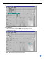
9-3. SOFTWARE SET UP
c Select the Serial port in the Control menu.
The GRAPHIC SWITCHER II™ is now connected to the computer.
d In the Input menu:
- Select the type of signal connected to the RGB / YUV inputs (RGB/YUV section).
- Select the COMPOSITE & S.VIDEO mode corresponding to your configuration (Composite & S.Video section).
- Select if necessary, the standard of the Composite & S.Video sources (Composite & S.Video section).
- Disable the unused input keys.
NOTE : Auto = Automatic recognition of the video standard.
PAGE 30
GRAPHIC SWITCHER II™
Chapter 9 : CONTROL SOFTWARE (continued)
9-3. SOFTWARE SET UP (continued)
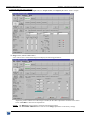
e In the Output menu, select the Output rate, the Output format, the Output Sync and the TALLY outputs.
f Image menus (MAIN & PREVIEW):
• If a video source is selected the image menu display the following parameters:
- Adjust the position and the size of the image. If needed, do the others adjustments available in this menu.
- Click on STORE to memorize the adjustments.
NOTE:
The RECALL function allows setting the stored image settings.
The FACTORY PRESET function sets all of the Image adjustments to the factory settings.
PAGE 31
Chapter 9 : CONTROL SOFTWARE (continued)
9-3. SOFTWARE SET UP (continued)
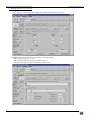
f Image menus (continued):
• If a computer source is selected the image menu display the following parameters:
g Effects menu: This menu allows to store effects in the Effects Keys.
- Select an Effect Key (1, 2, 3, or 4).
- Select one of the effects available in the Effects menu.
- Then adjust the options of the selected effect (duration, size...).
PAGE 32
GRAPHIC SWITCHER II™
GRAPHIC SWITCHER II™
Chapter 9 : CONTROL SOFTWARE (continued)
9-3. SOFTWARE SET UP (continued)
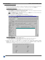
h Sequence menu:
This mode allows programming a sequence of transition. The sequence can also be activated at any time during the
show, and controlled step by step (one step = pre-selection + transition) by one key only: the STEP key.
• TO PROGRAM A SEQUENCE:
1 - Click on Add button in the Edit Sequence section to start the Add step function.
2 - Pre-Select an input source and select a transition (Effects Keys).
3 - Click on STEP button to add the step at the end of your sequence. The transition is displayed onto the MAIN
output and the description of the step is added in the table.
NOTE: For holding effect (i.e. : holding PIP): the first push on STEP allows to activate the effect and a
second push on STEP stops the effect.
4 - Renew the operations 2 and 3 to add new steps on your sequence.
5 - Click on Stop button in the Edit Sequence section to stop the Add Step function.
• TO PLAY A SEQUENCE:
1 - Click on Start button in the Play Sequence section.
2 - Click on STEP button to execute the first transition and pre-select the next source and so on.
3 - Click on Stop button in the Play Sequence section to stop the Play sequence function.
i Optional video output menu. THIS MENU IS AVAILABLE ONLY WITH THE OPTIONAL VIDEO
OUTPUT. The following functions act on the video outputs only (COMPOSITE VIDEO, S.VIDEO and
COMPONENT). See Chapter 7 : menu # 2-8 for the description of these functions.
PAGE 33
GRAPHIC SWITCHER II™
Chapter 10 : RS-232 PROGRAMMER'S GUIDE
10-1. INTRODUCTION
If you need to use your own Control Software from a PC, or WORKSTATION with an RS-232 port, the GRAPHIC
SWITCHER II™ allows communicating through an ASCII code protocol.
The GRAPHIC SWITCHER II™ treats any character received on its RS-232 as a possible command but, it only accepts
legal commands. There is no starting/ending in a command string.
A command can be 1 or 2 characters typed on a keyboard and does not require any special characters before or after it.
(it is not necessary to press "ENTER" on the keyboard). A command can be preceded by a value (see chapter 10-2.
COMMANDS STRUCTURE).
When the GRAPHIC SWITCHER II™ receives a valid command, it will execute the command. Then it will send back
the status of all the parameters that have changed due to this command from the control device.
For example: When you pre-select an input the GRAPHIC SWITCHER II™ indicates the input that you have preselected and the status of all its parameters (input standard, image adjustment,...)
If the command cannot be executed (value out of range, no signal on the selected input), the GRAPHIC SWITCHER
II™ just send back the current status of the corresponding parameters.
If the command is invalid, an error response will be returned to the controlling device. All responses sent to the
controlling device end with a carriage return <CR> and a line feed <LF> signaling the end of the response character
string. (see chapter 10-3. ERROR RESPONSES).
10-2. COMMANDS STRUCTURE
Commands are usually composed of a numerical value followed by the command characters (1 or 2). The characters
used without any numerical value return the current setting of the command.
COMMAND structure = VALUE (optional) + CHARACTER(S)
Examples:
COMMAND
VALUE
CHARACTER(S)
none fm
10 V
RESPONSE
OSYN0
VP10
DESCRIPTION
Read the Sync type of the MAIN output.
Set Vertical position to 10.
10-3. ERROR RESPONSES
When the GRAPHIC SWITCHER II™ receives from the controlling device an invalid command or value, it returns an
error response:
COMMAND
VALUE
CHARACTER(S)
none BB
70260 V
PAGE 34
RESPONSE
E10
E13
DESCRIPTION
Invalid command.
Invalid value.
GRAPHIC SWITCHER II™
Chapter 10 : RS-232 PROGRAMMER'S GUIDE (continued)
10-4. COMMANDS AND RESPONSES TABLE
The following table resumes all of the commands that are recognized as valid and the responses that will be returned to the
control device.
ASCII
RESPONSE
COMMAND
COMMAND
DESCRIPTION
FRONT PANEL COMMANDS
C
CH
MAIN selected input (read only).
c
ch
Input pre-selection (PREVIEW).
G
TAKE
TAKE (transition).
Z
FRZ
z
frz
M
STO
m
sto
R
REC
r
rec
H
HP
h
hp
V
VP
v
vp
W
HW
w
hw
S
VS
s
vs
INPUT COMMANDS
PC
PCH
PE
PEN
PL
PLD
PR
PRGB
TYPE
MIN MAX
Rd
Rd/Wr
Rd/Wr
0
0
0
21
21
1
FREEZE MAIN.
FREEZE PREVIEW.
STORE (MAIN).
STORE (PREVIEW).
RECALL (MAIN).
RECALL (PREVIEW).
Horizontal position (MAIN).
Horizontal position (PREVIEW).
Vertical position (MAIN).
Vertical position (PREVIEW).
Horizontal size (MAIN).
Horizontal size (PREVIEW).
Vertical size (MAIN).
Vertical size (PREVIEW).
Rd/Wr
Rd/Wr
Rd/Wr
Rd/Wr
Rd/Wr
Rd/Wr
Rd/Wr
Rd/Wr
Rd/Wr
Rd/Wr
Rd/Wr
Rd/Wr
Rd/Wr
Rd/Wr
0
0
0
0
0
0
0
0
0
0
0
0
0
0
1
1
1
1
1
1
255
255
255
255
255
255
255
255
Input selection for adjustment.
Input disabling (works with PC)
H sync load selection (works with PC).
RGB input type selection (works with
PC command).
Rd/Wr
Rd/Wr
Rd/Wr
Rd/Wr
0
0
0
0
21
1
1
6
PI
PSTD
Input standard selection (works with
PC command).
Rd/Wr
0
4
ys
ISHR
Composite or S.VIDEO mode
selection.
Rd/Wr
0
4
Output formats selection.
Rd/Wr
0
10
OUTPUT COMMANDS
F
OFMT
fm
OSYN
MAIN output sync selection.
Rd/Wr
0
2
fp
fs
pm
pp
osyn
SCRN
PAT
pat
REFR
PREVIEW output sync selection.
Type of screen selection
MAIN test pattern selection.
PREVIEW test pattern selection.
Input synchronization selection.
Rd/Wr
Rd/Wr
Rd/Wr
Rd/Wr
Rd/Wr
0
0
0
0
0
1
1
1
1
21
ADJR
ADJG
ADJB
Red level adjustment.
Green level adjustment.
Bleu level adjustment.
Rd/Wr
Rd/Wr
Rd/Wr
0
0
0
255
255
255
XR
ur
ug
ub
NOTE:
Rd = Read only command.
VALUE
DESCRIPTION
Please see value description (next section).
Please see value description (next section).
1 = start the transition (automatic reset at the
end of the effect duration).
0 = stop the transition (for holding effect).
0 = inactive
1 = active.
0 = inactive
1 = active.
1 = STORE action (automatic reset).
1 = STORE action (automatic reset).
1 = RECALL action (automatic reset).
1 = RECALL action (automatic reset).
Please see value description (next section).
0 = Input disable
1 = Input enable.
0 = Hi-Z load
1 = 75Ω load.
0 = SDTV YUV
4 = computer (SOG)
1 = SDTV RGBS (TTL) 5 = comp (HV or C.)
2 = SDTV RGsB (SOG) 6 = HDTV.
3 = SDTV RGBS (ana)
0 = automatic standard detection.
1 = NTSC.
2 = PAL.
3 = SECAM
4 = Black & White.
0 = 8 CV
3 = 2 CV + 3 SV
1 = 6 CV + 1 SV
4=
4 SV
2 = 4 CV + 2 SV
0 = VGA 60 Hz
6 = XGA 75 Hz
1 = SVGA 60 Hz
7 = D-ILA 4-3.
2 = XGA 60 Hz
8 = D-ILA 16/9
3 = SXGA 60 Hz
9 = 480p
4 = VGA 75 Hz
10 = 720p
5 = SVGA 75 Hz
0 = Separate H &V sync. 2 =SOG
1 = Composite sync.
0 = Separate H &V sync. 1 = Composite sync.
0 = 4/3 screen
1 = 16/9 screen
0 = OFF
1 = ON
0 = OFF
1 = ON
0 = Internal rate.
17 = S.VIDEO1 rate.
1 = RGB/YUV1 rate.
21 = SDI input rate.
9 = COMPOSITE 9 rate.
Rd/Wr = Read and write command.
PAGE 35
Chapter 10 : RS-232 PROGRAMMER'S GUIDE (continued)
GRAPHIC SWITCHER II™
10-4. COMMANDS AND RESPONSES TABLE (continued)
ASCII
RESPONSE
COMMAND
IMAGE COMMANDS
QO
OVR
qo
ovr
A
ASP
COMMAND
DESCRIPTION
TYPE
MIN MAX
VALUE
DESCRIPTION
Underscan / overscan (MAIN)
Underscan / overscan (PREVIEW)
Input aspect ratio selection (MAIN)
Rd/Wr
Rd/Wr
Rd/Wr
0
0
0
1
1
2
Input aspect ratio selection (PREV.)
Black level adjustment (MAIN).
Black level adjustment (PREVIEW).
Brightness adjustment (MAIN).
Brightness adjustment (PREVIEW).
Contrast adjustment (MAIN).
Contrast adjustment (PREVIEW).
Color adjustment (MAIN).
Color adjustment (PREVIEW).
Hue adjustment (MAIN).
Hue adjustment (PREVIEW).
Image process adjustment (MAIN).
Image process adjustment (PREVIEW)
Optimize adjustment (MAIN).
Optimize adjustment (PREVIEW).
Horizontal smoothing (MAIN).
Horizontal smoothing (PREVIEW).
Vertical smoothing (MAIN).
Vertical smoothing (PREVIEW).
PRESET (MAIN).
PRESET (PREVIEW).
Rd/Wr
Rd/Wr
Rd/Wr
Rd/Wr
Rd/Wr
Rd/Wr
Rd/Wr
Rd/Wr
Rd/Wr
Rd/Wr
Rd/Wr
Rd/Wr
Rd/Wr
Rd/Wr
Rd/Wr
Rd/Wr
Rd/Wr
Rd/Wr
Rd/Wr
Rd/Wr
Rd/Wr
0
0
0
0
0
0
0
0
0
0
0
0
0
0
0
0
0
0
0
0
0
2
255
255
255
255
255
255
255
255
255
255
7
7
255
255
1
1
1
1
1
1
Effect selection.
Effect duration selection.
Horizontal position of the effect.
Vertical position of the effect (PIP...)
Vertical size of the effect (PIP,
SHADOW...)
eH
EFs
Horizontal size of the PIP.
ex
EFx
Horizontal shape position (PIP) or
Intensity (Shadow title).
ey
EFy
Vertical shape position (PIP).
eX
EFX
Horizontal shape size (PIP).
eY
EFY
Vertical shape size (PIP).
g
EON
Effect in progress.
xC
ICHS
New background source during a POP.
TALLY OUTPUTS COMMANDS
ja
TALA
Input number for TALLY1
jb
TALB
Input number for TALLY2.
jc
TALC
Input number for TALLY3.
jd
TALD
Input number for TALLY4.
JA
TAON
TALLY1 status.
JB
TBON
TALLY2 status.
JC
TCON
TALLY3 status.
JD
TDON
TALLY4 status.
Rd/Wr
Rd/Wr
Rd/Wr
Rd/Wr
Rd/Wr
0
5
0
0
0
20
255
255
255
200
Rd/Wr
Rd/Wr
0
0
255
255
Rd/Wr
Rd/Wr
Rd/Wr
Rd
Rd
0
0
0
0
0
255
200
200
1
21
0 = no effect in progress. 1 = effect in progress.
Identical as c command.
Rd/Wr
Rd/Wr
Rd/Wr
Rd/Wr
Rd
Rd
Rd
Rd
1
1
1
1
0
0
0
0
21
21
21
21
1
1
1
1
Please see value description (next section).
Please see value description (next section).
Please see value description (next section).
Please see value description (next section).
0 = TALLY1 inactive
1 = TALLY1 active.
0 = TALLY2 inactive
1 = TALLY2 active.
0 = TALLY3 inactive
1 = TALLY3 active.
0 = TALLY4 inactive
1 = TALLY4 active.
a
asp
K
BLK
k
blk
B
BRG
b
brg
D
CON
d
con
O
COL
o
col
T
HUE
t
hue
QP
PRO
qp
pro
QF
QF
qf
qf
QH
QH
qh
qh
QV
QV
qv
qv
ym
PRES
yp
pres
EFFECTS COMMANDS
E
EFF
ed
EFD
eh
EFH
ev
EFV
es
EFS
PAGE 36
0 = underscan
1 = overscan
0 = underscan
1 = overscan
0 = 4/3 standard
1 = 16/9 letterbox
2 = 16/9 or WS anamorphic
Identical as A command
0 = level 1...................... 7 = level 8.
Identical as QP command.
0 = OFF
1 = ON
0 = OFF
1 = ON
0 = OFF
1 = ON
0 = OFF
1 = ON
1 = PRESET action (automatic reset).
1 = PRESET action (automatic reset).
Please see value description (next section).
Please see value description (next section).
0=0%
200 = 100 %
(For PIP : MIN value = 30).
0=0%
200 = 100 %
GRAPHIC SWITCHER II™
Chapter 10 : RS-232 PROGRAMMER'S GUIDE (continued)
10-4. COMMANDS AND RESPONSES TABLE (continued)
ASCII
COMMAND RESPONSE
STATUS COMMANDS
U
UNIT
IL
ILD
il
ild
ID
IFD
id
ifd
IP
IPS
ip
ips
IH
IHP
ih
ihp
IV
IVP
iv
ivp
IK
IST
ik
II
ii
IO
io
IF
if
XR
ist
IIN
iin
IOO
ioo
IFA
ifa
REFR
XA
XF
XT
REFA
REFF
REFT
COMMAND
DESCRIPTION
EPOS
DEMO
xi
I
xk
K_
xx
X_
xy
Y_
xs
S_
xd
D_
xa
A_
xb
B_
Y
FRES
OTHERS COMMANDS
L
CUT
N
TBP
@
@
ua
TBA
?
DEV
#
DEV12
VALUE
DESCRIPTION
Measures unity in kHz.
Horizontal period of input signal (M)
Horizontal period of input signal (P)
Vertical period of input signal (M)
Vertical period of input signal (P)
Input Sync. detection (MAIN).
Input Sync. detection (PREVIEW).
Sign of the horizontal input Sync. (M)
Sign of the horizontal input Sync. (P)
Sign of the vertical input Sync. (M)
Sign of the vertical input Sync. (P)
Input Sync type detection (MAIN).
Rd
Rd
Rd
Rd
Rd
Rd
Rd
Rd
Rd
Rd
Rd
Rd
0
0
0
0
0
0
0
0
0
0
0
0
Input Sync type detection (PREVIEW).
Interlaced signal detection (MAIN).
Interlaced signal detection (P).
"Out of range" signal detection (M).
"Out of range" signal detection (P).
Standard input signal detection (M).
Standard input signal detection (P).
Input synchronization selection.
Rd
Rd
Rd
Rd
Rd
Rd
Rd
Rd/Wr
0
0
0
0
0
0
0
0
Rd
Rd
Rd
0
0
0
Rd/Wr
0
31
Erase all memories.
Demo mode.
Rd/Wr
Rd/Wr
0
0
1
1
Identification number.
"K" Firmware Version.
"X" Firmware Version.
"Y" Firmware Version.
"S" Firmware Version.
"D" Firmware Version.
"A" Firmware Version.
"B" Firmware Version.
DEFAULT VALUE.
Rd
Rd
Rd
Rd
Rd
Rd
Rd
Rd
Rd/Wr
0
0
0
0
0
0
0
0
0
65535
65535
65535
65535
65535 Values displayed in hexadecimal in the
GSW2811R.
65535
65535
65535
1 1 = Default value action (automatic reset).
CUT effect.
T-BAR position.
Percentage of the executed effect.
T-BAR availability.
Device type.
Send all device parameters.
Rd/Wr
Rd/Wr
Rd
Rd
Rd
Rd
0
0
0
0
0
1
255
16383
1
65535
Synchronized input status.
Standard of the referenced input.
Frame frequency of the referenced
input.
CONTROLS COMMANDS
yl
LOCK
FRONT PANEL locking.
yc
yd
TYPE MIN MAX
65535
65535
65535
65535
65535
1
1
1
1
1
1
3
Please see value description (next section).
Please see value description (next section).
Please see value description (next section).
Please see value description (next section).
0 = no Sync. detected
1 = Sync. detected.
0 = no Sync. detected
1 = Sync. detected.
0 = negative
1 = positive.
0 = negative
1 = positive.
0 = negative
1 = positive.
0 = negative
1 = positive.
0 = Separate H &V sync.
1 = Composite sync. (TTL).
2 = SOG (Sync. On Green).
3 = Composite sync. (analog).
3 Identical as IK command.
1 0 = not interlaced
1 = interlaced.
1 0 = not interlaced
1 = interlaced.
1 0 = In range
1 = Out of range.
1 0 = In range
1 = Out of range.
27 Please see value description (next section).
27 Please see value description (next section).
21 0 = Internal rate
17 = S.VIDEO1 rate.
1 = RGB/YUV1 rate. 21 = SDI input rate.
9 = COMPOSITE 9 rate.
21 Identical as XR command.
27 Please see value description (next section).
65535 Value in Hz.
1 = locks the INPUT SELECT keys.
2 = locks the ADJUST buttons.
4 = locks the EFFECT keys.
8 = locks the CONTROL keys.
16 = lock the FREEZE keys.
1 = erase all memories (automatic reset).
0 = demo mode inactive.
1 = demo mode active.
1 = CUT action (automatic reset).
0 = 0%
16383 = 100%
0 = T-BAR unavailable. 1 = T-BAR available.
12 = GSW2811R/GSE2811R.
PAGE 37
Chapter 10 : RS-232 PROGRAMMER'S GUIDE (continued)
GRAPHIC SWITCHER II™
10-4. COMMANDS AND RESPONSES TABLE (continued)
ASCII
COMMAND
COMMAND RESPONSE
DESCRIPTION
SEQUENCE MODE COMMANDS
el
SEQS
Function of the sequence mode.
ei
SEQV
Validation of the selected function.
er
SEQC
Current step selection.
ut
tkev
Status of the pre-selected input.
VIDEO OUTPUT COMMANDS (OPTIONAL)
Qs
VSTD
Output video standard selection.
Qf
VAF
Anti-flicker level selection.
Qr
VREF
Reference signal of the video output.
Qv
VERV
Status of the video output version.
Qo
VOVR
Zoom mode selection.
ADD-ON-1 COMMANDS (OPTIONAL)
eS
EDGS
Size of the blending.
eA
EDGA
Position of the device in function of the
screen.
eC
PEDG
Image cutting.
eT
EDGT
Type of softedge
eP
eZ
ep
ez
eH
ek
eK
ej
eJ
EDPM
EDZM
EDPP
EDZP
EFs
EDFC
EDSC
EDFL
EDSL
MAIN image position.
MAIN image size.
PREVIEW image position.
PREVIEW image size.
Horizontal size of the PIP.
Softedge - Control point #1 (X)
Softedge - Control point #2 (X)
Softedge - Control point #1 (Y)
Softedge - Control point #2 (Y)
VALUE
DESCRIPTION
TYPE MIN MAX
Rd/Wr
Rd/Wr
Rd/Wr
Rd
0
0
1
0
5
1
40
1
Please see value description (next section).
Please see value description (next section).
Please see value description (next section).
Please see value description (next section).
Rd/Wr
Rd/Wr
0
0
1
2
Rd/Wr
0
2
0 = NTSC
0 = level 1
2 = level 3
0 = internal rate
2 = genlock.
Rd
Rd/Wr
0
0
Rd/Wr
Rd/Wr
0
0
Rd/Wr
Rd/Wr
0
0
Rd/Wr
Rd/Wr
Rd/Wr
Rd/Wr
Rd/Wr
Rd/Wr
Rd/Wr
Rd/Wr
Rd/Wr
0
0
0
0
0
1
1
1
1
65535
1 0 = overscan
1 = PAL
1 = level 2
1 = follow
1 = underscan.
255 0 = 0%
255 = 50%
255 bits 0-3: position of the device.
bits 4-7: number of device for the screen.
1 0 = inactive
1 = active.
255 0 = no softedge.
1 = linear softedge
bit 7 = active/inactive the softedge.
255
255
255
255
255
63
63
63
63
10-5. VALUES DESCRIPTION TABLE
ASCII
COMMAND
C
RESPONSE
CH
c
ch
PC
PCH
PAGE 38
COMMAND
DESCRIPTION
MAIN selected
input (read only).
Input pre-selection
(PREVIEW).
Input selection for
adjustment.
VALUE DESCRIPTION
0 Black
1 RGB/YUV #1 input
2 RGB/YUV #2 input
3 RGB/YUV #3 input
4 RGB/YUV #4 input
5 RGB/YUV #5 input
6 RGB/YUV #6 input
7 RGB/YUV #7 input
8 RGB/YUV #8 input
9 COMPOSITE #9 input
10 COMPOSITE #10 input
Identical as C command.
11
12
13
14
15
16
17
18
19
20
21
COMPOSITE #11 input
COMPOSITE #12 input
COMPOSITE #13 input
COMPOSITE #14 input
COMPOSITE #15 input
COMPOSITE #16 input
S.VIDEO #1 input
S.VIDEO #2 input
S.VIDEO #3 input
S.VIDEO #4 input
SDI input
0
1
2
3
4
5
6
7
8
9
10
11
12
13
14
15
16
17
18
19
20
21
COMPOSITE #11 input
COMPOSITE #12 input
COMPOSITE #13 input
COMPOSITE #14 input
COMPOSITE #15 input
COMPOSITE #16 input
S.VIDEO #1 input
S.VIDEO #2 input
S.VIDEO #3 input
S.VIDEO #4 input
SDI input
All inputs
RGB/YUV #1 input
RGB/YUV #2 input
RGB/YUV #3 input
RGB/YUV #4 input
RGB/YUV #5 input
RGB/YUV #6 input
RGB/YUV #7 input
RGB/YUV #8 input
COMPOSITE #9 input
COMPOSITE #10 input
GRAPHIC SWITCHER II™
Chapter 10 : RS-232 PROGRAMMER'S GUIDE (continued)
10-5.VALUES DESCRIPTION TABLE (continued)
ASCII
COMMAND
E
RESPONSE
EFF
ed
EFD
el
SEQS
ei
SEQV
er
SEQC
ut
tkev
ja
jb
jc
jd
IL
TALA
TALB
TALC
TALD
ILD
il
ild
ID
IFD
COMMAND
DESCRIPTION
Effect selection.
VALUE DESCRIPTION
00 = CUT.
01 = FADING: automatic from 0.5 to 25 seconds or T-BAR.
02 = TITLE: automatic from 0.5 to 25 seconds or T-BAR.
03 = TITLE: holding.
04 = SHADOW TITLE: automatic from 0.5 to 25 seconds or T-BAR.
05 = SHADOW TITLE: holding.
06 = HOR WIPE, Left to Right: automatic from 0.5 to 25 sec or T-BAR.
07 = HOR WIPE, Right to Left: automatic from 0.5 to 25 sec or T-BAR.
08 = HOR WIPE, to Center: automatic from 0.5 to 25 seconds or T-BAR.
09 = HOR WIPE, from Center: automatic from 0.5 to 25 sec or T-BAR.
10 = VERT WIPE, Up: automatic from 0.5 to 25 seconds or T-BAR.
11 = VERT WIPE, Down: automatic from 0.5 to 25 seconds or T-BAR.
12 = VERT WIPE, to Center: automatic from 0.5 to 25 seconds or TBAR.
13 = VERT WIPE, from Center: automatic from 0.5 to 25 sec or T-BAR.
14 = DIAMOND WIPE, to Center: automatic from 0.5 to 25 sec or TBAR.
15 = DIAMOND WIPE, from Center: automatic from 0.5 to 25 sec or TBAR.
16 = Normal PIP : automatic from 0.5 to 25 seconds or T-BAR.
17 = Normal PIP : holding.
18 = Fade PIP : automatic from 0.5 to 25 seconds or T-BAR.
19 = Fade PIP : holding.
20 = POP.
Effect duration selection (from 5 = 0.5 second
0.5s to 25.5 seconds by 0.1s
...
step).
255 = 25.5 seconds.
Selection of a function of the
0 = no function selected.
sequence mode.
1 = add step function.
2 = play sequence function.
3 = list sequence function.
4 = erase last function.
5 = clear sequence function.
Validation of the selected
1 = validate the selected function of the sequence mode (automatic reset).
function.
For example: • If add step selected, this command add a step into your
sequence.
• If erase last selected, this command erases the last step
of your sequence.
Current step selection.
1 = select step # 1.
......
40 = select step # 40.
Status of the pre-selected input The command indicates if the pre-selected input is ready to commute or
(read only).
not.
0 = pre-selected input not ready to commute. The validation of the
selected function can not be activate.
1 = pre-selected input ready to commute. The validation of the selected
function can be activate.
Input number for TALLY1
Identical as C command.
Input number for TALLY2
Identical as C command.
Input number for TALLY3
Identical as C command.
Input number for TALLY4
Identical as C command.
This command allows to
Line frequency (in kHz) = (UNIT VALUE) ÷ (ILD VALUE).
calculate the input line
frequency in Hz (MAIN).
This command allows to
Line frequency (in kHz) = (UNIT VALUE) ÷ (ild VALUE).
calculate the input frame
frequency in Hz (PREV).
This command allows to
Frame frequency (in Hz) = (Line frequency in Hz) ÷ (IFD VALUE).
calculate the input frame
frequency in Hz (MAIN).
PAGE 39
Chapter 10 : RS-232 PROGRAMMER'S GUIDE (continued)
GRAPHIC SWITCHER II™
10-5.VALUES DESCRIPTION TABLE (continued)
ASCII
COMMAND
id
RESPONSE
ifd
IF
IFA
if
XF
ifa
REFF
COMMAND
DESCRIPTION
This command allows to calculate the
input frame frequency in Hz (PREV).
Input standard detection (MAIN).
Input standard (PREVIEW)
Standard of the referenced input (read
only).
VALUE DESCRIPTION
Frame frequency (in Hz) = (Line frequency in Hz) ÷ (ifd
VALUE).
0 = no signal
15 = RGB 50 Hz
1 = "out of range" signal
16 = RGB 60 Hz
2 = NTSC std (3.58 / 60)
17 = VGA1 350L
3 = NTSC (3.58 / 50)
18 = VGA2 400L
4 = NTSC (4.43 / 60)
19 = VGA3 480L
5 = NTSC (4.43 / 50)
20 = PLASMA 42"
6 = PAL M (3.58 / 60)
21 = SVGA
7 = PAL comb (3.58 / 50)
22 = MAC
8 = PAL (4.43 / 60)
23 = XGA
9 = PAL std (4.43 / 50)
24 = PLASMA 50'
10 = SECAM (50Hz)
25 = MAC 21'
11 = Black and white (50Hz)
26 = SXGA
12 = Black and white (60 Hz)
27 = UXGA
13 = YUV 50 Hz
14 = YUV 60 Hz
Identical as IF command.
Identical as IF command.
10-6. ASCII / HEX / DEC TABLE
ASCII
space
!
"
#
$
%
&
’
(
)
*
+
,
.
/
0
1
2
3
4
5
6
7
8
9
:
;
<
=
>
?
PAGE 40
HEX
20
21
22
23
24
25
26
27
28
29
2A
2B
2C
2D
2E
2F
30
31
32
33
34
35
36
37
38
39
3A
3B
3C
3D
3E
3F
DEC
32
33
34
35
36
37
38
39
40
41
42
43
44
45
46
47
48
49
50
51
52
53
54
55
56
57
58
59
60
61
62
63
ASCII
@
A
B
C
D
E
F
G
H
I
J
K
L
M
N
O
P
Q
R
S
T
U
V
W
X
Y
Z
[
\
]
^
_
HEX
40
41
42
43
44
45
46
47
48
49
4A
4B
4C
4D
4E
4F
50
51
52
53
54
55
56
57
58
59
5A
5B
5C
5D
5E
5F
DEC
64
65
66
67
68
69
70
71
72
73
74
75
76
77
78
79
80
81
82
83
84
85
86
87
88
89
90
91
92
93
94
95
ASCII
`
a
b
c
d
e
f
g
h
i
j
k
l
m
n
o
p
q
r
s
t
u
v
w
x
y
z
{
|
}
~
DEL
HEX
60
61
62
63
64
65
66
67
68
69
6A
6B
6C
6D
6E
6F
70
71
72
73
74
75
76
77
78
79
7A
7B
7C
7D
7E
7F
DEC
96
97
98
99
100
101
102
103
104
105
106
107
108
109
110
111
112
113
114
115
116
117
118
119
120
121
122
123
124
125
126
127
GRAPHIC SWITCHER II™
Chapter 11 : TECHNICAL SPECIFICATIONS
RGB/YUV INPUTS
• COMPUTER FORMATS (PC, MAC , Workstation).
Hardware Compatibility: Line frequency : From 31.5 kHz to 130 kHz.
Resolutions : From 640 x 480 to 1600 x 1280.
Sync : Separate H & V, COMP, SOG.
Levels:
R, G, B = 3 x 0.7 Vp/p.
H & V Sync. = TTL.
Composite sync = TTL and 0.3 V.
SOG (Sync. On Green) = 0.3 V.
Impedance:
R, G, B = 75 ohms.
H = Hi-Z or 75 ohms.
V = 75 ohms.
• VIDEO FORMATS
• RGB/S (on 4 BNC connectors).
15.625 kHz / 50 Hz .... 15.735 kHz / 60 Hz (625L .....525L).
Levels:
R, G, B = 3 x 0.7 Vp/p.
Sync. = 0.3 V or TTL.
Impedance:
RGB = 75 ohms.
Sync. = 75 ohms or Hi-Z.
• Y DR DB (R-Y / Y / B-Y) COMPONENT (on 3 BNC connectors).
15.625 kHz / 50 Hz .... 15.735 kHz / 60 Hz (625L .....525L).
Levels:
Y = 1 Vp/p (0.7 V luma + 0.3 V sync).
Dr = 0.7 Vp/p.
Db = 0.7 Vp/p.
Impedance:
Y, Dr, Db = 75 ohms.
• HDTV FORMATS
•720p & 1080i
Levels:
R, G, B = 3 x 0.7 Vp/p.
Sync.:
H & V Sync. = TTL (Bi-level).
Impedance:
75 Ohms.
COMPOSITE & S.VIDEO INPUTS
• S.VIDEO (on 2 BNC connectors).
PAL / SECAM 15.625 kHz / 50 Hz (625L)
NTSC 3.58 MHz / 4.43 MHz 15.735 kHz / 60 Hz (525L)
Levels:
Y = 1 Vp/p (0.7 V luma + 0.3 V sync).
C = 0.3 Vp/p (chroma burst).
Impedance:
75 ohms.
• COMPOSITE VIDEO (on 1 BNC connector)
PAL / SECAM 15.625 kHz / 50 Hz (625L)
NTSC 3.58 MHz / 4.43 MHz 15.735 kHz / 60 Hz (525L)
Level:
1 Vp/p (0.7 V luma + 0.3 V sync).
Impedance:
75 ohms.
PAGE 41
Chapter 11 : TECHNICAL SPECIFICATIONS (continued)
GRAPHIC SWITCHER II™
SDI INPUT (Optional input on BNC connector).
Signal:
Component (4:2:2) serial digital input conforming to SMPTE-259M.
Data rate:
270 Mbps.
MAIN & PREVIEW OUTPUTS
• MAIN (on BNC & HD15 female connectors)
Levels:
R, G, B = 3 x 0.7 Vp/p.
Separate H & V Sync. = TTL.
Composite Sync = TTL.
SOG = 0.3 Vp/p.
Impedance:
75 ohms.
Resolution:
One of the available resolutions in the LCD screen menus.
• PREVIEW (on HD 15 female connector)
Levels:
R, G, B = 3 x 0.7 Vp/p.
Separate H & V Sync. = TTL.
Composite Sync = TTL.
Impedance:
75 ohms.
Resolution:
One of the available resolutions in the LCD screen menus.
REMOTE PORT & TALLY OUT
• REMOTE RS-232 (on DB 9 female connector)
Level:
RS-232.
Data Rate:
9600 Bauds, 8 data bits, 1 stop bit, no parity bit,
no flow control.
• TALLY OUT (on DB 9 female connector)
Rating:
20 Vdc, 50 mA (open collector).
PIN #
1
2
3
4
5
6
7
8
9
FUNCTION
tally # 1
Tx (transmit data)
Rx (receive data)
NC
Ground
tally # 2
tally # 3
NC
tally # 4
DB9 Female connector
OPTIONAL VIDEO OUTPUT
• COMPOSITE VIDEO (on BNC connector)
PAL / SECAM 15.625 kHz / 50 Hz (625L)
NTSC 3.58 MHz / 4.43 MHz 15.735 kHz / 60 Hz (525L)
Level:
1 Vp/p (0.7 V Luma + 0.3 V Sync.).
Impedance:
75 ohms.
• S.VIDEO (on DB9 connector)
PAL / SECAM 15.625 kHz / 50 Hz (625L)
NTSC 3.58 MHz / 4.43 MHz 15.735 kHz / 60 Hz (525L)
Levels:
Y = 1 Vp/p (0.7 V Luma + 0.3 V Sync.).
C = 0.3 Vp/p (chroma burst).
Impedance:
75 ohms.
PAGE 42
GRAPHIC SWITCHER II™
Chapter 11 : TECHNICAL SPECIFICATIONS (continued)
OPTIONAL VIDEO OUTPUT (continued)
• Y DR DB (R-Y / Y / B-Y) COMPONENT (on DB9 connector).
15.625 kHz / 50 Hz .... 15.735 kHz / 60 Hz (625L .....525L).
Levels:
Y = 1 Vp/p (0.7 V luma + 0.3 V sync).
Dr = 0.7 Vp/p.
Db = 0.7 Vp/p.
Impedance:
Y, Dr, Db = 75 ohms.
• DB9 PIN ASSIGNMENT
PIN #
1
2
3
4
5
6
7
8
9
FUNCTION
RTN
(red, green, bleu, genlock)
RED (R-Y)
GREEN (Y)
BLEU (B-Y)
Y (S.VIDEO)
genlock
RTN (Y+C)
C (S.VIDEO)
DB9 Female connector
ENVIRONMENTAL
Power Supply:
Internal CE / UL / CSA / IEC 950 (130W).
Input : 100VAC to 240VAC ; 50-60Hz ; I = 3A Max.
Storage Temperature:
-25 °C to +85 °C (-13 °F to +185 °F).
Operating temperature:
0 °C to 50 °C (32 °F to 122 °F).
Maximum ambient operating temperature:
< 40 °C ( < 104 °F).
Hygrometry:
10% to 80% (without condensation).
Dimension:
W 480 x D 340 x H 133mm / 19”W x 13.4”D x 5.2”H.
(Compatible with a Standard 19” rack, Height = 3 U).
Weight:
9 kg / 20 lbs. (without option)
9.5 kg / 21 lbs. (with the SDI (-D1) or the OPT-GSW2-VO option).
10 kg / 22 lbs. (with the SDI (-D1) and the OPT-GSW2-VO options).
PAGE 43
GRAPHIC SWITCHER II™
WARRANTY
Analog Way warrants the product against any defects in materials and workmanship for a period of three years from the date
of purchase (back to the factory).
In the event of any malfunction during the warranty period, Analog Way will, at its discretion, repair or replace the defective
units, including free materials and labor.
This warranty does not apply if the product has been :
- improperly installed or abused,
- handled with improper care,
- used or stocked in abnormal conditions,
- modified, opened,
- damaged by fire, war, or Natural disasters (Acts of God).
In no way shall Analog Way be responsible for direct or indirect loss of profit or consequential damages resulting from any
defect in this product.
In case of any problem, get the serial number of the unit, a description of the problem, and then call your authorized dealer.
PAGE 44