1
Analysis and presentation of plate loading tests
according to DIN 18134, DIN 18134:2010-04 (Draft)
or Austrian Standard B 4417
GGU-PLATELOAD
VERSION 8
Last revision:
September 2010
Copyright:
Prof. Dr. Johann Buß
Technical implementation and sales: Civilserve GmbH, Steinfeld
Contents:
1 Preface .................................................................................................................................. 4
2 Licence protection and installation..................................................................................... 4
3 Language selection ............................................................................................................... 4
4 Starting the program ........................................................................................................... 5
5 Description of menu items................................................................................................... 6
5.1 File menu.......................................................................................................................... 6
5.1.1 "New" menu item..................................................................................................... 6
5.1.2 "Load" menu item .................................................................................................... 7
5.1.3 "Save" menu item .................................................................................................... 7
5.1.4 "Save as" menu item ................................................................................................ 7
5.1.5 "Print output table" menu item................................................................................. 7
5.1.6 "Printer preferences" menu item .............................................................................. 8
5.1.7 "Print and export" menu item................................................................................... 8
5.1.8 "Batch print" menu item ........................................................................................ 10
5.1.9 "Exit" menu item ................................................................................................... 10
5.1.10 "1, 2, 3, 4" menu items........................................................................................... 10
5.2 Edit menu ....................................................................................................................... 11
5.2.1 "Preferences" ......................................................................................................... 11
5.2.2 "Test" menu item ................................................................................................... 11
5.2.3 "Target values" menu item..................................................................................... 12
5.2.4 "Weather conditions" menu item ........................................................................... 12
5.2.5 "Test times" menu item.......................................................................................... 12
5.2.6 "General" menu item.............................................................................................. 13
5.2.7 "Company" menu item........................................................................................... 13
5.2.8 "Remarks" menu item ............................................................................................ 13
5.3 Graphics preferences menu ............................................................................................ 13
5.3.1 "View output table"/"View diagram" menu item................................................... 13
5.3.2 "Preferences" menu item........................................................................................ 14
5.3.3 "Refresh and zoom" menu item ............................................................................. 15
5.3.4 "Zoom info" menu item ......................................................................................... 15
5.3.5 "Legend font selection" menu item........................................................................ 15
5.3.6 "Font size selection" menu item............................................................................. 15
5.3.7 "Pen colour and width" menu item ........................................................................ 16
5.3.8 "Mini-CAD toolbar" menu item ............................................................................ 16
5.3.9 "Toolbar preferences" menu item .......................................................................... 16
5.3.10 "Load graphics preferences" menu item ................................................................ 17
5.3.11 "Save graphics preferences" menu item................................................................. 17
5.4 Output preferences menu................................................................................................ 18
5.4.1 "Page size" menu item ........................................................................................... 18
5.4.2 "Texts" menu item ................................................................................................. 18
5.4.3 "Margins" menu item............................................................................................. 19
5.4.4 "Position info" menu item...................................................................................... 19
5.4.5 "Title (change position)" menu item ...................................................................... 19
5.4.6 "Deformation modulus" menu item ....................................................................... 20
GGU-PLATELOAD User Manual
Page 2 of 28
September 2010
5.4.7 "Company" menu item........................................................................................... 20
5.4.8 "Text no., etc." menu item ..................................................................................... 20
5.4.9 "Annex and report" menu item .............................................................................. 20
5.4.10 "Load-settlement curve" menu item....................................................................... 20
5.4.11 "Plate diameter" menu item ................................................................................... 21
5.4.12 "Remarks" menu item ............................................................................................ 21
5.4.13 "Short output table" menu item.............................................................................. 21
5.4.14 "Weather conditions" menu item ........................................................................... 21
5.4.15 "Target values" menu item..................................................................................... 21
5.4.16 "Test times" menu item.......................................................................................... 21
5.4.17 "First test (output table)" menu item...................................................................... 22
5.4.18 "Second test (output table)" menu item ................................................................. 22
5.4.19 "File name" menu item .......................................................................................... 22
5.4.20 "Reset all" menu item ............................................................................................ 23
5.4.21 "Move objects" menu item..................................................................................... 23
5.5 ? menu ............................................................................................................................ 24
5.5.1 "Copyright" menu item .......................................................................................... 24
5.5.2 "Maxima" menu item............................................................................................. 24
5.5.3 "Help" menu item .................................................................................................. 24
5.5.4 "GGU on the web" menu item ............................................................................... 24
5.5.5 "GGU support" menu item..................................................................................... 24
5.5.6 "What's new?" menu item...................................................................................... 24
5.5.7 "Language preferences" menu item ....................................................................... 24
6 Tips...................................................................................................................................... 25
6.1 Keyboard and mouse ...................................................................................................... 25
6.2 Function keys ................................................................................................................. 25
6.3 "Copy/print area" icon.................................................................................................... 26
7 Index.................................................................................................................................... 27
GGU-PLATELOAD User Manual
Page 3 of 28
September 2010
1 Preface
The program GGU-PLATELOAD enables the analysis and presentation of plate loading tests
according to DIN 18134, DIN 18134:2010-04 (Draft) or Austrian Standard B 4417.
Data input is in accordance with conventional WINDOWS operations and can therefore be learned
almost entirely without the use of a manual. Graphic output supports the true-type fonts supplied
with WINDOWS, so that excellent layout is guaranteed. Colour output and any graphics (e.g. files
in formats BMP, JPG, PSP, TIF, etc.) are supported. DXF files can also be imported by means of
the integrated Mini-CAD module (see the "Mini-CAD" manual).
The program has been thoroughly tested. No faults have been found. Nevertheless, liability for
completeness and correctness of the program and the manual, and for any damage resulting from
incompleteness or incorrectness, cannot be accepted.
2 Licence protection and installation
In order to guarantee a high degree of quality, a hardware-based copy protection system is used for
the GGU-PLATELOAD program.
The GGU software protected by the CodeMeter copy protection system is only available in
conjunction with the CodeMeter stick copy protection component (hardware for connection to the
PC, "CM stick"). Because of the way the system is configured, the protected software can only be
operated with the corresponding CM stick. This creates a fixed link between the software licence
and the CM stick copy protection hardware; the licence as such is thus represented by the CM
stick. The correct Runtime Kit for the CodeMeter stick must be installed on your PC.
Upon start-up and during running, the GGU-PLATELOAD program checks that a CM stick is
connected. If it has been removed, the program can no longer be executed.
For installation of GGU software and the CodeMeter software please refer to the information in
the Installation notes for GGU Software International, which are supplied with the program.
3 Language selection
GGU-PLATELOAD is a bilingual program. The program always starts with the language setting
applicable when it was last ended.
The language preferences can be changed at any time in the "?" menu, using the menu item
"Spracheinstellung" (for German) or "Language preferences" (for English).
GGU-PLATELOAD User Manual
Page 4 of 28
September 2010
4 Starting the program
After starting the program, you will see two menus at the top of the window:
• File
• ?
After clicking on the "File" menu, a previously calculated system can be loaded by means of the
"Load" menu item, or a new one created using "New".
The program allows simple input procedures by moving directly to the option box after "New" is
clicked; this can also be reached by pointing to the "File/New" menu item. You can now directly
select the standard to be adopted and the target values to be used. After leaving this box by pressing "OK" you will arrive at the initial program screen, containing all elements of the output sheet
that will be filled after data input.
Five menus then appear at the top of the window:
•
File
•
Edit
•
Graphics preferences
•
Output preferences
•
?
After clicking one of these menus, the so-called menu items roll down, allowing you access to all
program functions.
The program works on the principle of What you see is what you get. This means that the screen
presentation represents, overall, what you will see on your printer. In the last consequence, this
would mean that the screen presentation would have to be refreshed after every alteration you
make. For reasons of efficiency and as this can take several seconds for complex screen contents,
the GGU-PLATELOAD screen is not refreshed after every alteration.
If you would like to refresh the screen contents, press either [F2] or [Esc]. The [Esc] key additionally sets the screen presentation back to your current zoom, which has the default value 1.0, corresponding to an A4 format sheet.
GGU-PLATELOAD User Manual
Page 5 of 28
September 2010
5 Description of menu items
5.1
5.1.1
File menu
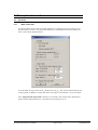
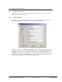
"New" menu item
You use this menu item to start a new plate loading test. A dialogue box opens, where you can
decide whether you want to use the German DIN 18134, the draft DIN 18134:2010 dated April
2010 or the Austrian Standard B 4417.
You can define the target values for Ev2 and the ratio of Ev2/Ev1, that will be checked and entered
by the program. In addition, a target value factor can be given, with which Ev1 can be correlated.
If the "Diagram with output table" check box is activated, a short output table is displayed together with the load-settlement curve evaluation (see also Section 5.4.13).
GGU-PLATELOAD User Manual
Page 6 of 28
September 2010
5.1.2
"Load" menu item
You can load a file with test data, which was created and saved at a previous sitting, and then edit
the test data.
5.1.3
"Save" menu item
You can save data entered or edited during program use to a file, in order to have them available at
a later date, or to archive them. The data is saved without prompting with the name of the current
file. Loading again later creates exactly the same presentation as was present at the time of saving.
5.1.4
"Save as" menu item
You can save data entered during program use to an existing file or to a new file, i.e. using a new
file name. For reasons of clarity, it makes sense to use ".pdr " as file suffix, as this is the suffix
used in the file requester box for the menu item "File/Load". If you choose not to enter an extension when saving, ".pdr " will be used automatically.
5.1.5
"Print output table" menu item
You can have an output table that can be sent to the printer or to a file (e.g. for further editing in a
word processor). Alternatively, you have the option of viewing the result in a separate window and
of editing them there.
• "Printer preferences" group box
Using the "Edit" button the current printer preferences can be changed or a different printer
selected. Using the "Save" button, all preferences from this dialogue box can be saved to a
file in order to have them available for a later session. If you select "GGUPLATELOAD.drk" as file name and save the file in the program folder (default), the file
will be automatically loaded the next time you start the program.
Using the "Page format" button you can define, amongst other things, the size of the left
margin and the number of lines per page. The "Header/footer" button allows you to enter a
header and footer text for each page. If the "#" symbol appears within the text, the current
page number will be entered during printing (e.g. "Page #"). The text size is given in "Pts".
You can also change between "Portrait" and "Landscape" formats.
GGU-PLATELOAD User Manual
Page 7 of 28
September 2010
• "Print pages" group box
If you do not wish pagination to begin with "1" you can add an "offset" number to the
check box. This offset will be added to the current page number. The output range is defined using "From page no." "to page no.".
• "Output to:" group box
Start output by clicking on "Printer" or "File". The file name can then be selected from or
entered into the box. If you select the "Window" button the results are sent to a separate
window. Further text editing options are available in this window, as well as loading, saving and printing.
5.1.6
"Printer preferences" menu item
You can edit printer preferences (e.g. swap between portrait and landscape) or change the printer
in accordance with WINDOWS conventions.
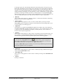
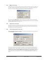
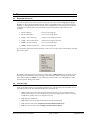
5.1.7
"Print and export" menu item
You can select your output format in a dialogue box. You have the following possibilities:
• "Printer"
allows graphic output of the current screen to the WINDOWS standard printer or to any
other printer selected using the menu item "File/Printer preferences". But you may also
select a different printer in the following dialogue box by pressing the "Printer
prefs./change printer" button.
GGU-PLATELOAD User Manual
Page 8 of 28
September 2010
In the upper group box, the maximum dimensions which the printer can accept are given.
Below this, the dimensions of the image to be printed are given. If the image is larger than
the output format of the printer, the image will be printed to several pages (in the above example, 4). In order to facilitate better re-connection of the images, the possibility of entering an overlap for each page, in x and y direction, is given. Alternatively, you also have the
possibility of selecting a smaller zoom factor, ensuring output to one page ("Fit to page"
button). Following this, you can enlarge to the original format on a copying machine, to ensure true scaling. Furthermore, you may enter the number of copies to be printed..
• "DXF file"
allows output of the graphics to a DXF file. DXF is a common file format for transferring
graphics between a variety of applications.
• "GGUCAD file"
allows output of the graphics to a file, in order to enable further processing with the
GGUCAD program. Compared to output as a DXF file this has the advantage that no loss
of colour quality occurs during export.
• "Clipboard"
The graphics are copied to the WINDOWS clipboard. From there, they can be imported
into other WINDOWS programs for further processing, e.g. into a word processor. In order
to import into any other WINDOWS program you must generally use the "Edit/Paste"
function of the respective application.
• "Metafile"
allows output of the graphics to a file in order to be further processed with third party software. Output is in the standardised EMF format (Enhanced Metafile format). Use of the
Metafile format guarantees the best possible quality when transferring graphics.
If you select the "Copy/print area" tool
from the toolbar, you can copy parts of
the graphics to the clipboard or save them to an EMF file. Alternatively you can send
the marked area directly to your printer (see "Tips", Section 6.3).
Using the "Mini-CAD" program module you can also import EMF files generated using
other GGU applications into your graphics.
• "MiniCAD"
allows export of the graphics to a file in order to enable importing to different GGU applications with the Mini-CAD module.
• "GGUMiniCAD"
allows export of the graphics to a file in order to enable processing in the GGUMiniCAD
program.
• "Cancel"
Printing is cancelled.
GGU-PLATELOAD User Manual
Page 9 of 28
September 2010
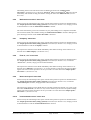
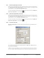
5.1.8
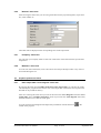
"Batch print" menu item
If you would like to print several appendices at once, select this menu item. You will see the following dialogue box:
Create a list of files for printing using "Add" and selecting the desired files. The number of files is
displayed in the dialogue box header. Using "Delete" you can mark and delete selected individual
files from the list. After selecting the "Delete all" button, you can compile a new list. Selection of
the desired printer and printer preferences is achieved by pressing the "Printer" button.
You then start printing by using the "Print" button. In the dialogue box which then appears you
can select further preferences for printer output such as, e.g., the number of copies. These preferences will be applied to all files in the list.
5.1.9
"Exit" menu item
After a confirmation prompt, you can quit the program.
5.1.10
"1, 2, 3, 4" menu items
The "1, 2, 3, 4" menu items show the last four files worked on. By selecting one of these menu
items the listed file will be loaded. If you have saved files in any other folder than the program
folder, you can save yourself the occasionally onerous rummaging through various sub-folders.
GGU-PLATELOAD User Manual
Page 10 of 28
September 2010
5.2
5.2.1
Edit menu
"Preferences"
A dialogue box opens, which can also be reached via the"File/New" menu item (see Section
5.1.1). The applicable standard and the target values can be edited.
5.2.2
"Test" menu item
This is the central menu item of the program. Here you can enter almost all base data for calculation. After clicking on this menu item the following dialogue box appears:
First, enter general information on your data collection point into the respective input boxes The
marked texts in the dialogue box also appear in the output sheet. Input boxes can be altered or
switched off such as "Station:" as shown in the above dialogue box by going to the menu item
"Output preferences/Texts" (see Section 5.4.2). The following buttons are then available:
• "Edit first test"
After clicking the button you reach a dialogue box, where you enter the manometer readings of each load increment (including the unloading). The entry of a negative manometer
reading characterises the end of the table. Then the entry of the dial gauge reading follows.
Newer plate loading apparatus only have one dial gauge for measuring the settlement of the
loading plate. So in order to avoid having to enter all the settlement readings three times
with the same value, the button "Gauge2/Gauge3:= Gauge1" exists. After clicking on this
button all the values entered under "Gauge 1" are assumed to "Gauge 2" and "Gauge 3".
• "Edit second test"
A dialogue box appears which enables the entry of the second loading cycle. Input is completely the same as described for the first loading cycle.
GGU-PLATELOAD User Manual
Page 11 of 28
September 2010
• "Show current data"
The data which belong to the latest test are calculated and shown.
• "Zero gauge readings"
The button allows all the dial gauge (first and second loading cycle) to be set on zero after
a confirmation prompt.
• "Import ASCII file"
You can import measured values received with plate loading apparatus from various companies.
• "Done"
After leaving the dialogue box by pressing the"Done" button the data is evaluated and all
input and results displayed on the output sheet.
5.2.3
"Target values" menu item
Using this menu item the target values for Ev2 and the ratio of Ev2/Ev1 can be defined. These values
will be checked and entered by the program, just as under the menu item "File/New". In addition,
a target value factor can be given, with which Ev1 can be correlated.
You can select the type of marker or annotation for the subsequent representation of the results if
the condition is fulfilled.
5.2.4
"Weather conditions" menu item
Corresponding informations about the weather can be entered.
5.2.5
"Test times" menu item
You can enter start and end time of a test.
GGU-PLATELOAD User Manual
Page 12 of 28
September 2010
5.2.6
"General" menu item
After selecting this menu item you can enter general data such as project designation, report number, annex number etc.
These data will be displayed in the corresponding areas of the output sheet.
5.2.7
"Company" menu item
You can enter your company adress in four lines. These lines will be entered at the top left of the
output sheet.
5.2.8
"Remarks" menu item
You can enter more information, such as deviations from the specified procedure or any observations made during the test.
5.3
5.3.1
Graphics preferences menu
"View output table"/"View diagram" menu item
By selecting the menu item "Graphics preferences/View output table" you can have the results
calculated by the program shown on the screen. This output table contains the most important test
data and can be printed for delivery.
After once selecting this menu item you will see the menu item "View diagram" instead of "View
output table" in the "Graphics preferences" menu. If you select the "View diagram" menu item,
the load-settlement curve will be visible again.
You can switch between diagram and output table presentation with the smarticon
toolbar of the program.
GGU-PLATELOAD User Manual
Page 13 of 28
in the
September 2010
5.3.2
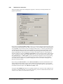
"Preferences" menu item
After selecting this menu item a dialogue box appears, in which you can edit preferences for
graphical presentation.
By activating the "Do not connect points" switch, you can ensure that the measured values are not
connected to a load-settlement curve. Only in rare cases, e.g. if you need to draw a load-settlement
curve by hand, you will use this switch. According to DIN 18 134, a 2nd degree polynomial using
compensation according to the least squares method is required for analysis of the plate loading
test. This method is utilised in all cases to determine the governing plate loading values, completely independently of the smoothing out procedure selected here. However, representation of
the plate loading test using the "2nd degree polynomial" switch sometimes leads to rather unusual
curves. Alternatively, then, and for optical effect only, you can select between the methods "Connect points linearly" or "Bezier spline" for the representation. Regardless of the selected setting
for the load-settlement curve you can separately specify a linear connection for the unloading
curve data points. In addition it is possible to display the secant in accordance with Figure 4 of
DIN 18134:2010-04 (draft).
By activating the "Show markers" or the "Show test numbers" switch the load-settlement curve
will be displayed with markers or their current numbers at all measuring points. You can switch
off both, when you only want to display the curve on the output sheet. The size of the markers can
be influenced with the input in the "Marker size [mm]:" field.
Using the "User-defined axes" button it is possible to define your own axes scales. Otherwise, the
axes will be scaled automatically. If you select this button you are first offered the automatic scale
values in a box, which you can then edit as required.
GGU-PLATELOAD User Manual
Page 14 of 28
September 2010
In addition, you can vary the number of decimal places for manometer data input between "3" and
"5" for each plate loading test performed.
The value a0 should be given in the evaluation of your plate loading test in compliance with DIN
18134:2010-04 (draft). Display in the "Deformation modulus" evaluation table can be achieved
by activating the check box "Enter a0 in table".
When you leave the dialogue box with "OK", all preferences will be accepted.
5.3.3
"Refresh and zoom" menu item
The program works on the principle of What you see is what you get. This means that the screen
presentation represents, overall, what you will see on your printer. In the last consequence, this
would mean that the screen presentation would have to be refreshed after every alteration you
make. For reasons of efficiency and as this can take several seconds for complex screen contents,
the screen is not refreshed after every alteration.
If, e.g., after using the zoom function (see below), only part of the image is visible, you can achieve a complete view using this menu item.
A zoom factor between 0.4 and 8.0 can be entered in the input box. By then clicking on "Use" to
exit the box the current factor is accepted. By clicking on the "0.4", "0.6", etc. buttons, the selected
factor is used directly and the dialogue box closed.
It is much simpler, however, to get a complete overview using [Esc]. Pressing [Esc] allows a complete screen presentation using the zoom factor specified in this menu item. The [F2] key allows
screen refreshing without altering the coordinates and zoom factor.
5.3.4
"Zoom info" menu item
By clicking two diametrically opposed points you can enlarge a section of the screen in order to
view details better. An information box provides information on activating the zoom function and
on available options.
5.3.5
"Legend font selection" menu item
With this menu item you can switch to a different true-type font. All available true-type fonts are
displayed in the dialogue box.
5.3.6
"Font size selection" menu item
You can edit font sizes for various text elements of your graphic.
GGU-PLATELOAD User Manual
Page 15 of 28
September 2010
5.3.7
"Pen colour and width" menu item
For reasons of clarity, different colours are used as default for graphic presentation of the loading
curves, as well as the type of dashing. With this menu item you can alter the preferences to suit
your wishes.
The pen width, line type and dashing can be edited for the load-settlement curves and, after clicking the corresponding buttons, the pen colours can be adapted.
On monochrome printers (e.g. laser printers), colours are shown in a corresponding grey scale.
Graphic elements employing very light colours may be difficult to see. In such cases it makes
sense to edit the colour preferences.
5.3.8
"Mini-CAD toolbar" menu item
Using this menu item you can add free text to the graphics and add lines, circles, polygons and
images (e.g. files in formats BMP, JPG, PSP, TIF, etc.) . A pop-up menu opens; the icons and
functions used are described in more detail in the "Mini-CAD" manual provided.
5.3.9
"Toolbar preferences" menu item
After starting the program a horizontal toolbar for menu items appears below the program menu
bar. If you would rather work with a popup window with several columns, you can specify your
preferences using this menu item. The smarticons can also be switched off.
At the bottom of the program window you find a status bar with further information. You can also
activate or switch off the status bar here. The preferences will be saved in the "GGUPLATELOAD.alg" file (see menu item "Graphics preferences/Save") and will be active at the
next time the program is started.
By clicking on the tools (smarticons) for menu items you can directly reach most of the program
functions. The meaning of the Smarticons appears as a text box if you hover with the mouse
pointer over the tools. Some of the tool functions can be activated from the normal menu items.
"Zoom out"
If you have previously zoomed in, this tool returns to a full screen display.
GGU-PLATELOAD User Manual
Page 16 of 28
September 2010
"Zoom (-)"/"Zoom (+)"
With the zoom functions you can zoom in or out of parts of the image, by clicking the left mouse
button.
"Undo move object"
If you have previously moved a legend ([F11] or used "Output preferences/Move objects"), you
can undo the last movement with this tool.
"Restore move object"
If you have previously undone a movement, you can restore with this tool.
"Copy/print area"
Use this tool to copy only parts of the graphics in order to paste them, e.g. to a report. You will see
information on this function and can then mark an area, which is copied to the clipboard or can be
saved in a file. Alternatively you can send the marked area directly to your printer (see "Tips",
Section 6.3).
"Diagram/output table"
By clicking on this tool you can switch between the load-settlement curve and the output table.
5.3.10
"Load graphics preferences" menu item
You can reload a graphics preferences file into the program, which was saved using the "Graphics
preferences/Save graphics preferences" menu item. Only the corresponding data will be refreshed.
5.3.11
"Save graphics preferences" menu item
Some of the preferences you made with the menu items of the "Graphics preferences" menu as
well as the inputs using the "Edit/Company" menu item can be saved to a file. If you select
"GGU-PLATELOAD.alg" as file name, and save the file on the same level as the program, the
data will be automatically loaded the next time the program is started and need not be entered
again.
If you do not go to "File/New" upon starting the program, but open a previously saved file
instead, the preferences used at the time of saving are shown. If subsequent changes in the
general preferences are to be used for existing files, these preferences must be imported using the menu item "Graphics preferences/Load graphics preferences".
GGU-PLATELOAD User Manual
Page 17 of 28
September 2010
5.4
5.4.1
Output preferences menu
"Page size" menu item
The default page set-up is A4 when the program is started. Using this menu item you can edit
height and width of the output sheet.
5.4.2
"Texts" menu item
The default labelling of some output sheet elements can be edited in this menu item's dialogue
box. Among other things, the name of the output sheet can be specified here.
Your input in the first row, "Manometer designation", will be used as column heading in the output tables. Your input in rows 1 to 6 of the above dialogue box, as well as the input for "Report:"
and "Annex:" also represent the designations for the input boxes in the "Edit/Test" and
"Edit/General" menu items dialogue boxes. If rows are deactivated in the above dialogue box, the
corresponding input boxes in the "Edit/Test" menu item dialogue box are also deactivated (see
Section 5.2.2). Use "Reset" to restore the default labelling settings.
GGU-PLATELOAD User Manual
Page 18 of 28
September 2010
5.4.3
"Margins" menu item
In the default program preferences the output sheet is shown with cutting borders. For output to an
A4 printer, a reduction of the printer output is generally necessary, as proprietary printers cannot
fully cover an A4 page. The margin preferences can be defined in a dialogue box.
By deactivating the "With borders" check box and with an appropriate choice of left and lower
margins, it is generally possible to create a non-reduced printer output. It is necessary to also adapt
the page height and width (see Section 5.4.1).
5.4.4
"Position info" menu item
The positions and layout of the individual elements on the output sheet can be altered using the
following menu items. This menu item provides information on the options for altering the position and layout more quickly using the mouse.
5.4.5
"Title (change position)" menu item
The position and layout of the title element can be altered via the dialogue box for this menu item,
if the "Title display" check box is activated.
The position of the element on the output sheet and its size can be defined or edited by means of
the variables "x" and "y", "dx" and "dy". The element can be provided with a frame and a background colour to suit your personal requirements. If the element needs to be returned to its original
condition, this can be done using the "Reset" button. Alternatively, you can alter the size and
shape of the element using the mouse (see menu item "Output preferences/Move objects", Section 0).
GGU-PLATELOAD User Manual
Page 19 of 28
September 2010
The heading shown in the title element can be edited in the menu item "Output preferences/Texts" (see Section 5.4.2). The texts "Project (1st line)" and "Project (2nd line)" are entered
immediately after double-clicking the element or using the menu item "Edit/General" (see Section 5.2.6).
5.4.6
"Deformation modulus" menu item
Almost exactly the same dialogue box opens with the same preference options as that described in
the "Output preferences/Title (change position)" menu item (see Section 5.4.5). Simply proceed
as described there to edit the "Deformation modulus" element.
The value a0 should be given in the evaluation of your plate loading test in compliance with DIN
18134:2010-04 (draft). After double-clicking the "Deformation modulus" element a dialogue box
opens allowing activation of the "Enter a0 in table" check box.
5.4.7
"Company" menu item
Almost exactly the same dialogue box opens with the same preference options as that described in
the "Output preferences/Title (change position)" menu item (see Section 5.4.5). Simply proceed
as described there to edit the "Company" element.
The input for this element can be edited immediately after double-clicking on the element or via
the menu item "Edit/Company" (see Section 5.2.7).
5.4.8
"Text no., etc." menu item
Almost exactly the same dialogue box opens with the same preference options as that described in
the "Output preferences/Title (change position)" menu item (see Section 5.4.5). To edit the
"Test no. etc.", element, simply proceed as described there.
The input for this element can be edited immediately after double-clicking on the element or via
the menu item "Edit/Test" (see Section 5.2.1). For this element you also have the option of adapting the texts in front of the input boxes to suit your needs. Go to the menu item "Output preferences/Texts " (see Section 5.4.2).
5.4.9
"Annex and report" menu item
Almost exactly the same dialogue box opens with the same preference options as that described in
the "Output preferences/Title (change position)" menu item (see Section 5.4.5). To edit the
"Annex and report" element, simply proceed as described there.
The input for this element can be edited directly by double-clicking the element or by going to the
menu item "Edit/General" (see Section 5.2.6). For this element you also have the option of adapting the texts in front of the input boxes to suit your needs. Go to the menu item "Output preferences/Texts " (see Section 5.4.2).
5.4.10
"Load-settlement curve" menu item
Almost exactly the same dialogue box opens with the same preference options as that described in
the "Output preferences/Title (change position)" menu item (see Section 5.4.5). Simply proceed
as described there to edit the "Load-settlement curve" element.
GGU-PLATELOAD User Manual
Page 20 of 28
September 2010
5.4.11
"Plate diameter" menu item
Almost exactly the same dialogue box opens with the same preference options as that described in
the "Output preferences/Title (change position)" menu item (see Section 5.4.5). Simply proceed
as described there to edit the "Platediameter" element.
5.4.12
"Remarks" menu item
Almost exactly the same dialogue box opens with the same preference options as that described in
the "Output preferences/Title (change position)" menu item (see Section 5.4.5). To edit the
"Remarks" element, simply proceed as described there.
The input for this element can be edited immediately after double-clicking on the element or via
the menu item "Edit/Remarks" (see Section 5.2.8).
5.4.13
"Short output table" menu item
Almost exactly the same dialogue box opens with the same preference options as that described in
the "Output preferences/Title (change position)" menu item (see Section 5.4.5). Simply proceed
as described there to edit the"Short output table" element.
5.4.14
"Weather conditions" menu item
Almost exactly the same dialogue box opens with the same preference options as that described in
the "Output preferences/Title (change position)" menu item (see Section 5.4.5). Simply proceed
as described there to edit the "Weather conditions" element.
The input for this element can be edited immediately after double-clicking on the element or via
the menu item "Edit/Weather conditions" (see Section 5.2.4).
5.4.15
"Target values" menu item
Almost exactly the same dialogue box opens with the same preference options as that described in
the "Output preferences/Title (change position)" menu item (see Section 5.4.5). Simply proceed
as described there to edit the "Target values" element.
The input for this element can be edited immediately after double-clicking on the element or via
the menu item "Edit/Target values" (see Section 5.2.3).
5.4.16
"Test times" menu item
Almost exactly the same dialogue box opens with the same preference options as that described in
the "Output preferences/Title (change position)" menu item (see Section 5.4.5). Simply proceed
as described there to edit the "Test times" element.
The input for this element can be edited immediately after double-clicking on the element or via
the menu item "Edit/Test times" (see Section 5.2.5).
GGU-PLATELOAD User Manual
Page 21 of 28
September 2010
5.4.17
"First test (output table)" menu item
Almost exactly the same dialogue box opens with the same preference options as that described in
the "Output preferences/Title (change position)" menu item (see Section 5.4.5). Simply proceed
as described there to edit the "First test (output table)"element.
To view the output table you must change to the output table using the menu item "Graphics preferences/View output table" or by clicking the
5.4.18
icon.
"Second test (output table)" menu item
Almost exactly the same dialogue box opens with the same preference options as that described in
the "Output preferences/Title (change position)" menu item (see Section 5.4.5). Simply proceed
as described there to edit the "Second test (output table)"element.
To view the output table you must change to the output table using the menu item "Graphics preferences/View output table" or by clicking the
5.4.19
icon.
"File name" menu item
If the button "Show legend" is activated, a legend with file informations will be diplayed on the
output sheet.
You can define and edit the position of the legend using the "x value" and "y value" and the size
of the legend using "Font size".
In addition to the prompted heading, you can have a designation before the file name. The file name can be excluded or displayed automatically with or without the file path and/or date and time.
GGU-PLATELOAD User Manual
Page 22 of 28
September 2010
5.4.20
"Reset all" menu item
With this button, all preferences for the aforementioned elements, which may have been edited
with the previous menu items, will be reset to the program defaults.
5.4.21
"Move objects" menu item
When you go to this item you can move the various objects with the aid of the mouse. Move the
mouse over the object to be moved. When you are located above a moveable object the mouse
pointer appears in the shape of a cross. You can now press and hold the left mouse button and drag
the object to the required position.
After going to this menu item only one object at a time can be moved using the mouse or its
size be altered.
In order to move or edit several objects, this function can be more quickly activated by
pressing [F11] or the
icon.
The size of an object can also be altered using this menu item or the [F11] key. If you move over
the frame of a changeable object after activating this function the mouse assumed the shape of a
double-headed arrow. Hold the left mouse button and move the frame until the object has reached
the required size. To retain the ratio of the sides, pull at one corner only. If on one side only is
pulled the object will become higher or wider.
The last change made in the position or size of an object can be undone using [Back] or by clicking the
icon.
GGU-PLATELOAD User Manual
Page 23 of 28
September 2010
5.5
5.5.1
? menu
"Copyright" menu item
You will see a copyright message and information on the program version number.
The "System" button shows information on your computer configuration and the folders used by
GGU-PLATELOAD.
5.5.2
"Maxima" menu item
Here you can check the defaults for maximum values.
5.5.3
"Help" menu item
The GGU-PLATELOAD help is opened as a PDF document. The help function can also be accessed using the [F1] function key.
5.5.4
"GGU on the web" menu item
Using this menu item you can access the GGU Software website: www.ggu-software.com.
Keep in touch with new program versions and the regular download offers.
If you would like to be automatically notified about program innovations, please register for the
Newsletter in our Knowledge Base. Go to the following website: http://kbase.civilserve.com.
5.5.5
"GGU support" menu item
This menu item takes to the GGU-Software Support area at www.ggu-software.com.
5.5.6
"What's new?" menu item
You will see information on program improvements in comparison to older versions.
5.5.7
"Language preferences" menu item
This menu item allows you to switch the menus and the graphics from German to English and vice
versa. To work in German, deactivate the two check boxes "Dialoge + Menüs übersetzen (translate dialogues, menus)" und "Graphiktexte übersetzen (translate graphics)".
Alternatively, you can work bilingually, e.g. with German dialogue boxes but with graphic output
in English. The program always starts with the language setting applicable when it was last ended.
GGU-PLATELOAD User Manual
Page 24 of 28
September 2010
6 Tips
6.1
Keyboard and mouse
You can scroll the screen with the keyboard using the cursor keys and the [Page up] and [Page
down] keys. By clicking and pulling with the mouse, with [Ctrl] pressed, you activate the zoom
function, i.e. the selected section will fill the screen. Furthermore you can use the mouse wheel to
zoom in/out or scrolling the screen presentation. The following mouse wheel functions are
available:
• Mouse wheel up
= move screen image up
• Mouse wheel down
= move screen image down
• [Ctrl] + mouse wheel up
= enlarge screen image (zoom in)
• [Ctrl] + mouse wheel down
= shrink screen image (zoom out)
• [Shift] + mouse wheel up
= move screen image right
• [Shift] + mouse wheel down
= move screen image left
If you click the right mouse button anywhere on the screen a context menu containing the principal
menu items opens.
By double-clicking the left mouse button on output sheet or Mini-CAD objects, the editor for the
selected object immediately opens, allowing it to be edited. By double-clicking output sheet elements while holding the [Shift] key, the preferences for the position, size and appearance of the
element open for editing in the editor.
6.2
Function keys
Some of the function keys are assigned program functions. The allocations are noted after the corresponding menu items. The individual function key allocations are:
•
[Esc] refreshes the screen contents and sets the screen back to the given format. This is
useful if, for example, you have used the zoom function to display parts of the screen and
would like to quickly return to a complete overview.
• [F1] opens the online-help.
• [F2] refreshes the screen without altering the current magnification.
• [F3] opens the menu item "Graphics preferences/Refresh and zoom".
• [F11] activates the menu item "Output preferences/Move objects".
GGU-PLATELOAD User Manual
Page 25 of 28
September 2010
6.3
"Copy/print area" icon
A dialogue box opens when the "Copy/print area" icon
in the menu toolbar is clicked, describing the options available for this function. For example, using this icon it is possible to either
copy areas of the screen graphics and paste them into the report, or send them directly to a printer.
In the dialogue box, first select where the copied area should be transferred to: "Clipboard",
"File" or "Printer". The cursor is displayed as a cross after leaving the dialogue box and, keeping
the left mouse button pressed, the required area may be enclosed. If the marked area does not suit
your requirements, abort the subsequent boxes and restart the function by clicking the icon again.
If "Clipboard" was selected, move to the MS Word document (for example) after marking the
area and paste the copied graphics using "Edit/Paste".
If "File" was selected, the following dialogue box opens once the area has been defined:
The default location of the file is the folder from which the program is started and, if several files
are created, the file is given the file name "Image0.emf" with sequential numbering. If the
"Rename" button in the dialogue box is clicked, a file selector box opens and the copied area can
be saved under a different name in a user-defined folder. Saving can be aborted by pressing the
"Delete" button.
If the "Printer" button was pressed in the first dialogue box, a dialogue box for defining the printer settings opens after marking the area. Following this, a dialogue box for defining the image
output settings opens. After confirming the settings the defined area is output to the selected printer.
GGU-PLATELOAD User Manual
Page 26 of 28
September 2010
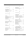
7 Index
2
G
2 degree polynomial....................................... 14
Gauge, set to zero ............................................. 12
GGUCAD file, export......................................... 9
GGUMiniCAD file, export ................................. 9
Graphics, integrate using Mini-CAD ................ 16
nd
A
a0, activate display ..................................... 15, 20
Annex number, edit element............................. 20
Annex number, enter ........................................ 13
ASCII file, import from plate loading
apparatus ...................................................... 12
Austrian standard B 4417, activate ..................... 6
Axes scales, define ........................................... 14
I
Installation .......................................................... 4
K
Knowledge Base, access ................................... 24
B
L
Base data, enter for test..................................... 11
C
Clipboard ............................................................ 9
CodeMeter stick.................................................. 4
Colour/pens, define for load-settlement curve .. 16
Company data, edit element ............................. 20
Company data, enter ......................................... 13
Condition fulfilled, activate display.................. 12
Context menu, open.......................................... 25
Copy/print area ....................................... 9, 17, 26
Cutting borders, turn on/off .............................. 19
D
Data import, from plate loading apparatus........ 12
Deformation modulus, edit element.................. 20
DIN 18134, activate............................................ 6
DXF file, export.................................................. 9
DXF file, import ................................................. 4
E
Language preferences ................................... 4, 24
Least squares method........................................ 14
Licence protection .............................................. 4
Load-settlement curve, activate display............ 13
Load-settlement curve, define colour/pens ....... 16
Load-settlement curve, edit display settings ..... 14
Load-settlement curve, edit element ................. 20
Load-settlement curve, switch to output table .. 17
M
Manometer, define dimension .......................... 11
Manometer, specify decimal places .................. 15
Margins, define................................................. 19
Markers, define for load-settlement curve ........ 14
Measure point data, edit element ...................... 20
Measure point data, edit input box texts ........... 18
Measure point data, enter.................................. 11
Metafile, export .................................................. 9
Mini-CAD file, export ........................................ 9
Mini-CAD, use ................................................. 16
Mouse click functions....................................... 25
Mouse wheel functions ..................................... 25
EMF format ........................................................ 9
Ev1 value, activate testing ............................. 6, 12
Ev2 value, enter ............................................. 6, 12
F
File, display name in legend ............................. 22
File, load/save..................................................... 7
First test, edit output table element ................... 22
First test, enter data........................................... 11
Font sizes, define .............................................. 15
Font, select........................................................ 15
Function keys.................................................... 25
GGU-PLATELOAD User Manual
O
Output sheet, alter position/size of
individual elements using mouse............ 19, 23
Output sheet, change name ............................... 18
Output sheet, edit title element ......................... 19
Output sheet, reset all elements to defaults....... 23
Output sheet, reset individual elements
to defaults..................................................... 19
Output table, activate display............................ 13
Output table, edit manometer column heading . 18
Output table, print............................................... 7
Output table, switch to load-settlement curve... 17
Page 27 of 28
September 2010
P
Page numbering, automatically in output table... 7
Page section,copy/print............................... 17, 26
Page size, define ............................................... 18
Pen preferences, load-settlement curve............. 16
Plate diameter, edit element.............................. 21
Plate diameter, enter ......................................... 11
Plate substratum, enter...................................... 11
Print, graphics..................................................... 8
Print, output table ............................................... 8
Print, section ........................................... 9, 17, 26
Print, several files ............................................. 10
Printer preferences.......................................... 7, 8
Program, load/save preferences ........................ 17
Program, show improvements .......................... 24
Program, show information .............................. 24
Project data, edit element.................................. 19
Project data, enter ............................................. 13
R
Ratio Ev2/Ev1, enter ....................................... 6, 12
Remarks, edit element ...................................... 21
Remarks, enter.................................................. 13
Report number, edit element............................. 20
Report number, enter ........................................ 13
S
Scroll the screen ............................................... 25
Secant, activate display..................................... 14
Second test, edit output table element............... 22
Second test, enter data ...................................... 11
Short output table, activate display......... 6, 11, 21
Short output table, edit element ........................ 21
GGU-PLATELOAD User Manual
Smarticons, for menu items .............................. 16
Standard, select............................................. 6, 11
Status bar main program, activate..................... 16
System, show information ................................ 24
T
Target values, define............................... 6, 11, 12
Target values, edit element ............................... 21
Test numbers, activate display.......................... 14
Test results, display in message box ................. 12
Test times, edit element .................................... 21
Test times, enter................................................ 12
Tests, display maximum number ...................... 24
Tests, enter base data ........................................ 11
Toolbar, for menu items.................................... 16
Translation, activate.......................................... 24
Transmission ratio, enter................................... 11
True-type font ................................................... 15
U
Unloading curve, edit display settings .............. 14
Unloading, enter data........................................ 11
W
Weather conditions, edit element...................... 21
Weather conditions, enter ................................. 12
What you see is what you get ........................... 15
Z
Zoom factor, define for full-screen display....... 15
Zoom function, activate ........................ 15, 17, 25
Page 28 of 28
September 2010