1
RFI filtering is included as a standard feature. It greatly reduces conducted interference which could affect
sensitive equipment. The control contains barrier terminals as standard; however, quick disconnect
terminals can be provided as an option. A potentiometer (5K), isolated analog signal (0-10 VDC), or PWM
microprocessor output can be used to vary the output of the control.
TABLE 1 – ELECTRICAL RATINGS & MECHANICAL SPECIFICATIONS
Model KBWD-15 Rated 5.0 Amps DC @ 115 VAC 50/60 Hz
SPECIFICATIONS
Output Voltage Range (VDC) . . . . . . . . . . . . . . . . . . . . . . . . . . . . . . . . . . . . . . . . . . . . . . . . . . . . 0 – 130
Speed Range (Ratio) . . . . . . . . . . . . . . . . . . . . . . . . . . . . . . . . . . . . . . . . . . . . . . . . . . . . . . . . . . . . . 50:1
Operating Frequency (kHz) . . . . . . . . . . . . . . . . . . . . . . . . . . . . . . . . . . . . . . . . . . . . . . . . . . . . . . . . . >16
Form Factor (RMS / Avg Amps) . . . . . . . . . . . . . . . . . . . . . . . . . . . . . . . . . . . . . . . . . . . . . . . . . . . <1.05
Ambient Operating Range Temp (°C). . . . . . . . . . . . . . . . . . . . . . . . . . . . . . . . . . . . . . . . . . . . . . . . 0 – 45
Load Regulation (% Base Speed) . . . . . . . . . . . . . . . . . . . . . . . . . . . . . . . . . . . . . . . . . . . . . . . . . . . . . 1*
Timed CL Trimpot Range (TCL) (Seconds) . . . . . . . . . . . . . . . . . . . . . . . . . . . . . . . . . . . . . . . . . . . . 1 – 7
Acceleration Trimpot Range (ACCEL) (Seconds) . . . . . . . . . . . . . . . . . . . . . . . . . . . . . . . . . . . . 0.5 – 15
Minimum Speed Trimpot Range (MIN) (VDC) . . . . . . . . . . . . . . . . . . . . . . . . . . . . . . . . . . . . . . . . . 0 – 40
Maximum Speed Trimpot Range (MAX) (VDC) . . . . . . . . . . . . . . . . . . . . . . . . . . . . . . . . . . . . . . 70 – 130
Current Limit Trimpot Range (CL) (% Range Setting) . . . . . . . . . . . . . . . . . . . . . . . . . . . . . . . . . . 0 – 200
IR Comp Trimpot Range (IR) (VDC) . . . . . . . . . . . . . . . . . . . . . . . . . . . . . . . . . . . . . . . . . . . . . . . . 0 – 15
AC Line Voltage Regulation (% Base Speed) . . . . . . . . . . . . . . . . . . . . . . . . . . . . . . . . . . . . . . . . . . . 0.5
Analog Input Voltage (Voltage Following) (VDC) . . . . . . . . . . . . . . . . . . . . . . . . . . . . . . . . . . . . . . . 0 – 10
Speed Potentiometer - 5 watt (Ohms) . . . . . . . . . . . . . . . . . . . . . . . . . . . . . . . . . . . . . . . . . . . . . . . . . . 5K
*Based on motor having linear IR Comp characteristics.
®
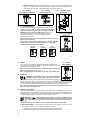
PLUG-IN HORSEPOWER RESISTOR®
A Plug-in Horsepower Resistor must be installed to match the control to the motor
horsepower and armature current. See table 2, p. 5 for the correct value.
Plug-in Horsepower Resistors® are stocked by your distributor.
CAUTION: Be sure Plug-in Horsepower Resistor® is inserted completely into
mating socket.
3
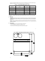
FIG. 1 – CONTROL LAYOUT
Illustrates factory setting of jumpers and approximate setting of trimpots
4