1
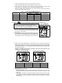
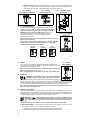
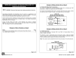
iii. Microprocessor Input – An isolated PWM signal from a microprocessor can be used to operate the
control. The output frequency should be 200 Hz or greater and should be derived from an
optocoupler with a transistor or operational amplifier signal output. (See fig. 7)
FIG. 5 – REMOTE
POTENTIOMETER CONNECTION
V.
FIG. 6 – ANALOG
VOLTAGE CONNECTION
FIG. 7 – MICROPROCESSOR
CONNECTION
DC TACHOMETER INPUT.
If tachometer feedback is required, an analog tach signal must be
connected to terminal block TB3. Note: For tachometer feedback,
Jumper J1 must be set for the proper tach voltage, and the IR
COMP must be set to minimum (CCW) position. Connect the
tachometer so that when the motor rotates, the positive tach
voltage lead is connected to T+ and the negative tach lead is
connected to T-. (See fig. 8.)
FIG. 8 – TACHOMETER
CONNECTION
Note: If the tach voltage is connected backwards, the control will drive
the motor at full speed only.
NOTE: Use the "7V" position for tachometer with 7 volts per 1000 RPM
and the "50V" position for tachometer with 50 volts per 1000 RPM.
(Set IR Comp to minimum for tach feedback.)
ARMATURE
FEEDBACK
TACH
7V/1000 RPM
TACH
50V/1000 RPM
9
VI.
INHIBIT
The control can be electronically stopped and started with the Inhibit circuit. To
"Stop" the control, terminals I1 & I2 must be shorted via a contact. The control
can be restarted by opening the contact.
FIG. 9 – INHIBIT
CIRCUIT WIRING
Note: The Inhibit should not be used as a safety disconnect. Use only the
AC line for that purpose. (See fig. 9, p. 10)
Note: The Inhibit Circuit is not isolated. Do not earth ground inhibit leads.
VII. OPERATION
WARNING! Read Safety Warning on page 1 before attempting to
operate the control or severe injury or electrocution can result.
After the control has been set up properly and the wiring has been completed, the
start-up procedure can begin. If AC power has been properly connected to the control, the "ON" LED
indicator will illuminate. Before starting, be sure the main potentiometer is in the minimum position. To start
the control, the potentiometer knob should be rotated clockwise; the motor should begin to rotate.
Note: If the motor rotates in the incorrect direction, it will be necessary to disconnect the main AC
power and reverse the armature wires.
VIII. TRIMPOT ADJUSTMENTS
The control contains trimpots which have been factory adjusted for most applications. Figure 1, p. 4
illustrates the location of the trimpots and their approximate adjustment positions. Some applications may
require readjustment of the trimpots in order to tailor the control to exact requirements. (See table 1, p. 3
for range and factory setting of all trimpots.) Readjust trimpots as follows:
WARNING. Do not adjust trimpots with main power on if possible. If adjustments are
made with power on, insulated adjustment tools must be used and safety glasses must be
worn. High voltage exists in this control. Electrocution and/or fire can result if caution is
not
exercised. Safety warning on page 1 must be read and understood before proceeding.
A. Minimum Speed (MIN) — The MIN trimpot is used to set the minimum voltage of the drive. This sets
the minimum speed of the motor. Adjust the MIN trimpot as follows:
1. Rotate Main Potentiometer to minimum speed position (full counterclockwise).
2. Increase setting of MIN trimpot so that motor runs at desired minimum speed.
10