1
INTERNATIONAL JOURNAL OF COMPUTERS AND COMMUNICATIONS
As we can see we have a Connect button for connecting the
computer to the oscilloscope. This buttons sends the
command, which puts the equipment in remote mode. During
this time, the physical buttons from the oscilloscope are not
functional, it pressed they make an error beep. An LED
indicator on the oscilloscope indicates that the equipment is in
remote mode and can be commanded just with a computer. On
the graphical interface the status of the oscilloscope is shown
with and edit text indicator, where the information ON or OFF
is shown, depending on the state of the oscilloscope (remote or
local).
To return to local mode, the Autoset button from the
oscilloscope need to be pushed for a few seconds and the
oscilloscope will return in local mode. The Autoset button’s
secondary function is returning the oscilloscope in local mode.
After this operation the oscilloscope will not be commanded
eth the PC, just with the buttons physically present on the
equipment and the remote LED will be turned off. To return
the oscilloscope in local mode, the disconnect button from the
computer interface can be used too.
The Autoset button from the user interface has the same
effect as the Autoset button physically present on the
oscilloscope; it sets the Time/DIV and Volt/DIV parameters
most optimal to the acquisitioned signal.
For setting the horizontal (X-POS.) and vertical (Y-POS. I
and Y-POS. II) positions of the signal, sliders were used. Here
a little trick need to be used, because for positive vertical
position was one command and for negative vertical position
was another command, but only one slider was used, so the
two commands needed to be merged in one.
For setting the timebase (TIME/DIV.) and the amplitude
(VOLTS/DIV. I and VOLTS/DIV.), also sliders were used.
Because sliders, were fuzzy, a more accurate solution was
needed, to set exactly the timebase and the amplitude, this way
pop-up menus were used. For timebase between 1 µs/DIV.
and 0,5 s/DIV., for amplitude between 1 mV/DIV. and 20
V/DIV. The values can be set exactly. For the timebase and
amplitude, both controls are functional, for exact and for fuzzy
setting of the signal.
For saving the signal form the oscilloscope two buttons are
used Read Wavef. I (for CH I) and Read. Wavef. II (for CH
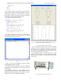
II). The signal will be shown on the axe. The acquisitioned
signal has 256 samples (256 points), for larger signals more
samples need to be combined. The serial interface has a buffer
of 512 samples.
For writing a saved waveform from the computer to the
oscilloscope, the Write Wavef. I and Write Wavef. II buttons
were used. The oscilloscope has two memories and this way it
can memorize to signals. The signals are saved in a text file
(signal.txt) as points. This can be used for saving each signal
from each channel to the computer, make some signal
processing and after that send it back to the equipment. In the
signal.txt file also is a signal with 256 samples (256 points).
Here also a little trick is needed to make it work, the
oscilloscope need to be put in STOR. MODE, so the REF bit
has to be put on “1” logic by software, otherwise it will not
work. This is very important to be done, because otherwise if
Issue 3, Volume 3, 2009
the REF bit is not activated manually on the oscilloscope, the
saving of a signal will not work and an error beep will be
received.
C. The Code behind the buttons
In this section the code behind the buttons is explained.
Every SCPI command needs to be ended with carriage
return (CR, 0Dh or 13d). There are exceptions too, some of
them needs only CR and other CR and LF, depends on the
SCPI command.
These SCPI commands can be obtained from the
oscilloscopes user manual or from an existing program with
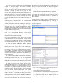
the HHD Free Serial Monitor program (Fig. 3 and Fig. 4.).
With this program we can obtain the SCPI commands that the
existing program uses.
Fig. 3. The HHD Serial Monitor program configured.
Fig. 4. The HHD Serial Monitor program obtaining SPCI commands from
and existing program.
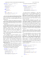
TABLE I shows the used SCPI commands.
These commands are obtained from the user guide or from
an existing program using the Free Serial Monitor program.
We obtained them from the user manual, because we
couldn't find an existing program for our oscilloscope.
35