1
User's Manual
AD-130GE
Digital 2CCD Progressive Scan
Multi-Spectral Camera
Document Version: 1.1
AD-130GE_Ver.1.1_Mar2012
1036E-1201
AD-130GE
Notice
The material contained in this manual consists of information that is proprietary to JAI Ltd.,
Japan and may only be used by the purchasers of the product. JAI Ltd., Japan makes no
warranty for the use of its product and assumes no responsibility for any errors which may
appear or for damages resulting from the use of the information contained herein. JAI Ltd.,
Japan reserves the right to make changes without notice.
Company and product names mentioned in this manual are trademarks or registered
trademarks of their respective owners.
Warranty
For information about the warranty, please contact your factory representative.
Certifications
CE compliance
As defined by the Directive 2004/108/EC of the European Parliament and of the Council, EMC
(Electromagnetic compatibility), JAI Ltd., Japan declares that AD-130GE complies with the
following provisions applying to its standards.
EN 61000-6-3 (Generic emission standard part 1)
EN 61000-6-2 (Generic immunity standard part 1)
FCC
This equipment has been tested and found to comply with the limits for a Class B digital device,
pursuant to Part 15 of the FCC Rules. These limits are designed to provide reasonable
protection against harmful interference in a residential installation. This equipment
generates, uses and can radiate radio frequency energy and, if not installed and used in
accordance with the instructions, may cause harmful interference to radio communications.
However, there is no guarantee that interference will not occur in a particular installation. If
this equipment does cause harmful interference to radio or television reception, which can be
determined by turning the equipment off and on, the user is encouraged to try to correct the
interference by one or more of the following measures:
- Reorient or relocate the receiving antenna.
- Increase the separation between the equipment and receiver.
- Connect the equipment into an outlet on a circuit different from that to which the receiver
is connected.
- Consult the dealer or an experienced radio/TV technician for help.
Warning
Changes or modifications to this unit not expressly approved by the party
responsible for FCC compliance could void the user’s authority to operate the
equipment.
2
AD-130GE
Supplement
The following statement is related to the regulation on “ Measures for the Administration
of the control of Pollution by Electronic Information Products “ , known as “ China RoHS “.
The table shows contained Hazardous Substances in this camera.
mark shows that the environment-friendly use period of contained Hazardous
Substances is 15 years.
嶷勣廣吭並㍻
嗤蕎嗤墾麗嵎賜圷殆兆各式根楚燕
功象嶄鯖繁酎慌才忽佚連恢匍何〆窮徨佚連恢瞳麟半陣崙砿尖一隈〇云恢瞳ゞ 嗤蕎嗤
墾麗嵎賜圷殆兆各式根楚燕 〃泌和
桟隠聞喘豚㍉
窮徨佚連恢瞳嶄根嗤議嗤蕎嗤墾麗嵎賜圷殆壓屎械聞喘議訳周和音氏窟伏翌
亶賜融延、窮徨佚連恢瞳喘薩聞喘乎窮徨佚連恢瞳音氏斤桟廠夛撹冢嶷麟半
賜斤児繁附、夏恢夛撹冢嶷鱒墾議豚㍉。
方忖仝15々葎豚㍉15定。
AD-130GE
Table of Contents
JAI GigE® Vision Camera operation manuals ............................................................ 7
Introduction ................................................................................................. 7
Before using GigE Vision camera .......................................................................... 7
Software installation ....................................................................................... 7
Camera Operation .......................................................................................... 8
1. General.................................................................................................. 8
2. Camera nomenclature ................................................................................ 8
3.
Main Features ......................................................................................... 9
4.
Locations and functions ............................................................................10
4.1. Locations and functions .......................................................................10
4.2.
Rear Panel Indicator ...........................................................................11
5.
Pin configuration & DIP switch ....................................................................12
5.1. 12-pin Multi-connector (DC-in/GPIO/Iris Video) ...........................................12
5.2. Digital Output Connector for Gigabit Ethernet ............................................12
5.3.
6-pin Multi-connector (LVDS IN and TTL IN/OUT) .........................................12
5.4. DIP switches.....................................................................................13
5.4.1 SW800 Trigger input 75 ohms termination ...........................................13
5.4.2 SW100 TTL/Open collector output select ............................................13
5.4.3 SW700 Video output for Auto iris lens.................................................13
6.
System Configuration .............................................................................14
6.1.
System connection .............................................................................14
6.2. RJ-45 outputs ...................................................................................14
6.3.
Sync Mode .......................................................................................15
6.4. Lens considerations ............................................................................15
7.
Inputs and outputs interface .....................................................................16
7.1.
Overview ........................................................................................16
7.1.1 LUT (Cross Point Switch) ..................................................................16
7.1.2 12-bit Counter ..............................................................................17
7.1.3 Pulse Generators (0 to 3) .................................................................17
7.2. Opto-isolated Inputs/Outputs ................................................................17
7.2.1 Recommended External Input circuit diagram for customer ........................18
7.2.2 Recommended External Output circuit diagram for customer ......................18
7.2.3 Optical Interface Specifications .........................................................19
7.3. Input and output circuits......................................................................19
7.3.1 Iris Video output ...........................................................................19
7.3.1.1 Iris Video input and output .........................................................20
7.3.1.2 Iris video output select ..............................................................20
7.3.2 Trigger input ................................................................................20
7.3.3 EEN (Exposure Enable) output ...........................................................21
7.4. GPIO Inputs and outputs table ...............................................................22
7.5.
Configuring the GPIO module.................................................................23
7.5.1 Input /Output Signal Selector ............................................................23
7.5.2 Pulse generators (20 bit x 4) .............................................................23
7.5.3 GPIO interface in GenICam standard ....................................................24
7.5.4 Change polarity ............................................................................24
7.5.5 The restrictions to use TTL In I/F in the AD-130GE ...................................25
7.5.6 Caution when the software trigger is used .............................................26
7.6.
GPIO programming examples .................................................................28
7.6.1 GPIO Plus PWC shutter ....................................................................28
3
AD-130GE
7.6.2 Internal Trigger Generator ...............................................................29
Video Signal Output .................................................................................30
8.1. Sensor layout ...................................................................................30
8.2.
Partial scan (JAI Partial Scan ON) ...........................................................31
8.3.
Digital Video Output (Bit Allocation) ........................................................32
8.3.1 Bit Allocation (Pixel Format / Pixel Type) – (monochrome sensor) .................32
8.3.1.1 GVSP_PIX_MONO8 (8bit) .............................................................32
8.3.1.2 GVSP_PIX_MONO10 (10bit) ........................................................32
8.3.1.3 GVSP_PIX_MONO10_PACKED (10 bit) ..............................................33
8.3.1.4 GVSP_PIX_MONO12 (12 bit) .........................................................33
8.3.1.5 GVSP_PIX_MONO12_PACKED (12 bit) ..............................................33
8.3.2 Bit Allocation (Pixel Format / Pixel Type) – (Bayer mosaic color sensor) ..........33
8.3.2.1 GVSP_PIX_BAYRG8 ―BayerRG8‖ ....................................................33
8.3.2.2 GVSP_PIX_BAYRG10 ―Bayer RG10‖ ................................................34
8.3.2.3 GVSP_PIX_BAYRG12 ―Bayer RG12‖ ................................................34
8.3.2.4 GVSP_PIX_BAYRG10_Packed (Bayer10bit, Packed output) .....................34
8.3.2.5 GVSP_PIX_BAYRG12_Packed (Bayer12bit, Packed output) ................34
8.3.2.4 GVSP_PIX_RGB8_PACKED ―RGB 8Packed‖ ........................................34
8.3.2.5 GVSP_PIX_RGB10V1_PACKED ―RGB 10V1 Packed‖ ...............................35
8.3.2.6 GVSP_PIX_RGB10V2_PACKED ―RGB 10V2 Packed‖ ...............................35
8.4. Video timing ....................................................................................36
8.4.1 Horizontal Timing ..........................................................................36
8.4.2
Vertical Timing ..........................................................................37
8.4.3 Partial Scan Vertical Timing ..............................................................38
9. Network configuration ..............................................................................40
9.1.
GigE Vision Standard Interface ...............................................................40
9.2.
Equipment to configure the network system...............................................40
9.2.1 PC ............................................................................................40
9.2.2 Cables........................................................................................40
9.2.3 Network card (NIC) ........................................................................40
9.2.4 Hub ...........................................................................................41
9.3. Recommended Network Configurations .....................................................41
9.3.1
Guideline for network settings .........................................................41
9.3.2 Video data rate (network bandwidth) ..................................................42
9.3.3 Simplified calculation (Approximate value) ............................................43
9.3.4 Note for 100BASE-TX connection ........................................................44
9.4.
GigE camera connecting examples ..........................................................44
9.4.1 Using a switching hub for 1 port .........................................................44
9.4.2 Connecting a camera to each port of a multi-port NIC ...............................45
9.4.3 The data transfer for multiple cameras ................................................45
9.4.3.1 If delayed readout is not used in continuous mode .............................45
9.4.3.2 If delayed readout is not used in trigger mode ..................................46
9.4.3.3 If delayed readout is used ..........................................................46
10. Functions (Conforming to GenICam SFNC 1.3) ....................................................47
10.1.
Acquisition function ..........................................................................47
10.1.1 Basic image acquisition flow ............................................................47
10.1.2 Acquisition mode .........................................................................48
10.1.2.1 Single Frame .........................................................................48
10.1.2.2 Continuous mode ...................................................................49
10.2.
Trigger Control ................................................................................50
10.2.1 TriggerSelector(TriggerMode) ...........................................................50
8.
4
AD-130GE
10.2.1.1 Acquisition ...........................................................................50
10.2.1.2 Exposure .............................................................................50
10.2.2 Triggersoftware ...........................................................................51
10.2.3 Triggersource ...............................................................................51
10.2.4 TriggerActivation...........................................................................51
10.3.
Exposure Control ..............................................................................52
10.3.1 Exposure Mode ............................................................................52
10.3.2 ExposureTime .............................................................................52
10.3.3 ExposureAuto ...............................................................................53
10.4.
ActionControl..................................................................................53
10.4.1 ActionDeviceKey ..........................................................................53
10.4.2 ActionSelector ............................................................................53
10.4.3 ActionGroupMask .........................................................................53
10.4.4 ActionGroupKey ...........................................................................53
10.5.
Operation Mode ..............................................................................53
10.5.1 The exposure timing when the trigger pulse is input................................54
10.5.1.1 Auto-detect LVAL-sync / async accumulation ..................................54
10.5.1.2 Relation between the external trigger mode and LVAL Sync/Async ........54
10.5.2
Continuous mode .........................................................................55
10.5.3
Edge Pre-Select (EPS) trigger mode....................................................55
10.5.4 Pulse Width Control (PWC) trigger mode .............................................59
10.5.4.1 Timing chart .........................................................................59
10.5.5
Smearless mode ...........................................................................61
10.5.5.1 Sync=Sync, LVAL Async, Smearless Enable=True, EPS trigger ................61
10.5.5.2
Sync Mode=Sync, LVAL Async, Smearless Enable=True, PWC trigger ......62
10.5.6 Reset Continuous Trigger (RCT) mode .................................................63
10.5.7
Sequential Trigger Mode (EPS) ..........................................................64
10.5.7.1 Setting parameters .................................................................64
10.5.7.2 Initial settings .......................................................................66
10.5.8
Delayed Readout EPS and PWC Modes .................................................66
10.5.9
Multi ROI mode (Multi Region of Interest) ............................................67
10.5.9.1 Setting parameters .................................................................67
10.5.9.2 Initial parameters ...................................................................68
10.5.10 Optical Black transfer mode ...........................................................68
10.6.
Operation Mode and Functions matrix .....................................................69
10.6.1.
Sync Mode = SYNC .......................................................................69
10.6.2
SYNC Mode = Async .......................................................................69
11.
Other functions ....................................................................................70
11.1.
Basic functions ................................................................................70
11.1.1 2CCD optical assembly ...................................................................70
11.1.2
Electronic shutter ........................................................................70
11.1.3
Shading correction........................................................................71
11.1.4 White balance .............................................................................72
11.1.5
Blemish compensation ...................................................................72
11.1.6
Test signal generator.....................................................................73
11.2.
Control Tool Screen ..........................................................................73
11.2.1 Feature Tree Information ...............................................................73
11.2.2 Feature Properties (Guru) ...............................................................73
12.
External Appearance and Dimensions ...........................................................79
13.
Specifications.......................................................................................80
13.1.
Spectral response .............................................................................80
5
AD-130GE
13.2.
Specification Table ...........................................................................81
Appendix ....................................................................................................83
1. Precautions ........................................................................................83
2. Typical Sensor Characteristics ..................................................................83
3. Caution when mounting a lens on the camera ...............................................83
4. Caution when mounting the camera ...........................................................84
5. Exportation ........................................................................................84
6. References.........................................................................................84
Change History .............................................................................................85
User's Record ...............................................................................................86
6
AD-130GE
JAI GigE® Vision Camera operation manuals
To understand and operate this JAI GigE® Vision camera properly, JAI provides the following
manuals.
User’s manual (this booklet)
Describes functions and operation of the hardware
JAI SDK & Control Tool User Guide Describes functions and operation of the Control Tool
JAI SDK Getting Started Guide Describes the network interface
User’s manual is available at www.jai.com
JAI SDK & Control Tool User Guide and JAI SDK Getting Started Guide are provided with the JAI
SDK which is available at www.jai.com.
Introduction
GigE Vision is the new standard interface using Gigabit Ethernet for machine vision applications
and it was mainly set up by AIA (Automated Imaging Association) members. GigE Vision is
capable of transmitting large amounts of uncompressed image data through an inexpensive
general purpose LAN cable for a long distance.
GigE Vision also supports the GenICamTM standard which is mainly set up by the EMVA (European
Machine Vision Association). The purpose of the GenICam standard is to provide a common
program interface for various machine vision cameras. By using GenICam, cameras from
different manufactures can seamlessly connect in one platform.
For details about the GigE Vision standard, please visit the AIA web site,
www.machinevisiononline.org and for GenICam, the EMVA web site, www.genicam.org.
JAI GigE Vision cameras comply with both the GigE Vision standard and the GenICam standard.
Before using GigE Vision camera
All software products described in this manual pertain to the proper use of JAI GigE Vision
cameras. Product names mentioned in this manual are used only for the explanation of
operation. Registered trademarks or trademarks belong to their manufacturers.
To use the JAI SDK, it is necessary to accept the ―Software license agreement‖ first.
This manual describes necessary equipment and the details of camera functions.
Software installation
The JAI GigE Vision SDK & Control Tool can be downloaded from the JAI web site at
www.jai.com. The JAI SDK is available for Windows XP and Vista, 32-bit and 64-bit.
For the details of software installation, please refer to the ―Getting Started Guide‖ supplied on
the JAI SDK download page.
7
AD-130GE
Camera Operation
1. General
This manual covers the digital 2-CCD progressive scan multi-spectral camera AD-130GE.
The AD-130GE is a GigE Vision compliant camera, belonging to the JAI C3 Advanced family. The
AD-130GE employs 2 CCDs, one for Bayer color and the other for NIR monochrome utilizing
prism optics so that the AD-130GE can inspect the objects by visible color sensor and Near IR
sensor with the same angle of view.
The AD-130GE provides a frame rate of 31 frames/second at full resolution. Using partial scan,
the camera can achieve faster frame rates up to 145 fps (8 lines height).
The 1/3" CCDs with square pixels offer a superb image quality. The high-speed shutter function
and asynchronous random trigger mode allows the camera to capture high quality images of
fast moving objects.
The camera features a built-in pre-processing function which includes blemish compensation,
shading compensation, Bayer to RGB interpolation, LUT/gamma correction and knee control.
The AD-130GE also complies with the GenICam standard and contains an internal XML file that
is used to describe the functions/features of the camera. For further information about the
GigE Vision Standard, please go to www.machinevisiononline.org and about GenICam, please
go to www.genicam.org.
As an application programming interface, JAI provides an SDK (Software Development Kit). This
SDK includes GigE Vision Filter Driver, JAI Control tool, software documentation and code
examples.
The JAI SDK can be downloaded from www.jai.com.
The latest version of this manual can be downloaded from www.jai.com
For camera revision history, please contact your local JAI distributor.
2. Camera nomenclature
The standard camera composition consists of the camera main body and C-mount protection
cap.
The camera is available in the following versions:
AD-130GE
Where A stands for "Advanced" family, D stands for "Dual CCD", 130 represents the resolution
"1.3 million pixels", 130 indicates that this is the first dual-CCD model with this resolution, and
GE stands for "GigE Vision" interface.
8
AD-130GE
3.
Main Features
C3 Advanced series progressive scan camera
GigE Vision, GenICam compliant
Multi-spectral 2-channel CCD camera
Simultaneously captures Visible and Near-IR through the same optical path
1/3‖ progressive scan IT CCDs with 1296 (h) x 966 (v) active pixels
3.75 μm square pixels
RGB 24-bit or 32-bit or Raw Bayer 12- or 10- or 8-bit output for visible
12- or 10- or 8-bit output for Near-IR
30 frames/second with full resolution
Variable partial scan is available with user-definable height and starting line
Programmable exposure from 0.4L(11.49μs) to 982L(31.761ms)
Edge Pre-select, Pulse Width Control and Reset Continuous trigger modes
Sequence trigger mode for on-the –fly change of gain, exposure and ROI
Delayed read out mode for smooth transmission of multi camera applications
Blemish compensation built in
Shading compensation circuit built in
LUT (Look Up Table) for gamma correction
AGC (Automatic Gain Control) from 0dB to 21dB
LVAL synchronous/asynchronous operation (auto-detect)
Auto-iris lens video output for lens control
Programmable GPIO with opto-isolated inputs and outputs
Comprehensive software tools and SDK for Windows XP/Vista/7 (32 bit ―x86‖ and 64
bit ―x64‖ JAI SDK Ver. 1.2.1 and after )
9
AD-130GE
4.
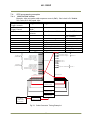
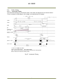
Locations and functions
4.1.
Locations and functions
CCD sensor
Lens Mount
12P Multi Connector
LED
6P Multi Connector
RJ-45 Connector(GigE 1)
RJ-45 Connector(GigE2)
Holes for RJ-45 thumbscrews
Holes for RJ-45 thumbscrews
Mounting holes
:
:
:
:
:
:
:
:
:
:
1/3 inch CCD sensor
C-mount ( Note*1 )
DC+12V and Trigger Input
Power and Trigger indications
LVDS IN and TTL IN and OUT
GigE Vision I/F w/ thumbscrews for color
GigE Vision I/F w/ thumbscrews for NIR
Vertical type (Note*2)
Vertical type (Note *2)
M3, max length 5mm (Note*3)
*1) : AD-130GE is based on a Dichroic Prism. For optimal performance, lenses designed for
3CCD cameras should be used with this camera. Be sure to avoid lenses that contain IR filters
as this will impair the operation of the NIR sensor. Rear protrusion of the C-mount lens must
be less than 4mm to avoid damage to the prism.
*2) : When an RJ-45 cable with thumbscrews is connected to the camera, please do not excessively
tighten screws by using a screw driver. The RJ-45 receptacle on the camera might be
damaged. For security, the strength to tighten screws is less than 0.147 Newton meter (Nm).
Tightening by hand is sufficient in order to achieve this.
*3) : The tripod adapter plate MP-41 can be used with AD-130GE
Fig.1 Locations
10
AD-130GE
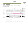
4.2.
Rear Panel Indicator
The rear panel mounted LED provides the following information:
Amber
Steady green
Flashing green
: Power connected – initiating
: Camera is operating in Continuous mode
: The camera is receiving external trigger
Steady green
Flashing green
■ Amber
:
DCIN/TRIG
GPIO
POW
ER/TRIG
8
1
■
Connecting 1000Base-T:Link
: Connecting 100Base-T/10Base-T:Link
: GigE Network:Act
GigE-1
1
8
GigE-2
Fig.2 Rear
panel
Note: In 10BASE-T connection, no signal is output.
11
AD-130GE
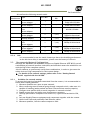
5.
Pin configuration & DIP switch
5.1.
12-pin Multi-connector (DC-in/GPIO/Iris Video)
Type: HR10A-10R-12PB
(Hirose) male.
(Seen from the rear of
camera)
9
1
2
8
10
11
3
4
7
12
6
5
Fig. 3. 12-pin connector.
5.2.
Pin no.
Signal
Remarks
1
GND
2
+12 V DC input
3
Opt IN 2 (-) / GND (*1)
4
Opt IN 2 (+)/Iris Video out (*1)
5
Opt IN 1 ( - )
6
Opt IN 1 ( + )
GPIO IN / OUT
7
Opt Out 1 ( - )
8
Opt Out 1 ( + )
9
Opt Out 2 ( - )
10
Opt Out 2 ( + )
11
+ 12 V DC input
12
GND
*1: Iris Video output function can be set by the internal DIP switch
(SW700).
Digital Output Connector for Gigabit Ethernet
Type: RJ-45 : HFJ11-1G02E-L21RL or equivalent
8
6
7
5 4
3
2
1
The digital output signals follow
the Gigabit Ethernet interface
using an RJ-45 conforming
connector. To the right is a table
with the pin assignment for
Gigabit Ethernet connector.
Fig. 4. Gigabit Ethernet
connector
5.3.
Pin No
1
2
3
4
5
6
7
8
In/Out
In/Out
In/Out
In/Out
In/Out
In/Out
In/Out
In/Out
In/Out
Name
MX1+ (DA+)
MX1- (DA-)
MX2+ (DB+)
MX3+ (DC+)
MX3- (DC-)
MX2- (DB-)
MX4+ (DD+)
MX4- (DD-)
6-pin Multi-connector (LVDS IN and TTL IN/OUT)
Type : HR-10A-7R-6PB
1
6
3
4
2
5
Fig.5 HIROSE 6-pin connector
No I/O
Name
Note
1
I LVDS In 12
I LVDS In 1+
3
I TTL IN 1
75ohm Terminator (Note*1)
4
O TTL Out 1 Note*2)
5
I TTL IN 2
75ohm Terminator(Note*1)
6注
GND
*1:can be changed by DIP switches.
*2: Open collector or TTL level can be selected by an
internal DIP switch. Factory default is TTL.
12
AD-130GE
5.4.
DIP switches
SW700 for lens iris
SW800 for 75 ohms
termination
SW100 for selecting
TTL output
5.4.1
SW800 Trigger input 75 ohms termination
Trigger input can be terminated with 75 ohms if DIP switch SW600 is selected as
described below. Factory default is open.
TTL
75 Ω
Note: Toward upper side of camera body
① TTL IN 1
② TTL IN 2
5.4.2
SW100 TTL/Open collector output select
EEN output through HIROSE 6-pin #4 can be selected TTL level or open collector level.
The selection is activated by DIP switch SW100 described below.
TTL
OPEN
Note: Toward upper side of camera body
5.4.3
SW700 Video output for Auto iris lens
The output through HIROSE 12-pin #4 can be selected OPT IN 2 or Iris video output by DIP
switch SW700 described below. Factory default is OPT IN 2.
OPT IN
IRIS
Note: Toward inner side of camera body
13
AD-130GE
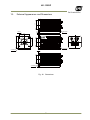
6. System Configuration
6.1.
System connection
When the AD-130GE is connected to a PC, there are two connection methods.
Method one is to use dual or quad input Network Interface Card (NIC) or two separate network
interface cards. The other way is to use a hub as shown below.
2 x RJ45
Dual input NIC or 2 NICs
2 x RJ45
HUB
1 NIC with HUB
Fig.6 System configuration
It should be noted that the hub being used should comply with Gigabit Ethernet.
When JAI SDK control tool is started, AD-130GE is recognized as two cameras. #0 represents the
Bayer color imager and #1 represents the NIR imager.
Each imager can be handled as an independent camera.
Two image sensors can be operated either in SYNC mode or ASYNC mode.
This can be set by the ―Sync mode command‖.
6.2.
RJ-45 outputs
The AD-130GE has two RJ-45 connectors, one for color sensor output and the other for the
monochrome NIR sensor. The output for the color sensor is through GigE-1 and monochrome NIR
output is through GigE-2. These two outputs can be set at synchronous (SYNC) or asynchronous
(ASYNC) in Sync Mode feature.
Color CCD
Image
Process
Frame
Memory
MAC PHY
RJ45 GigE-1
NIR CCD
Image
Process
Frame
Memory
MAC PHY
RJ45 GigE-2
Fig.7 RJ-45 output system
14
AD-130GE
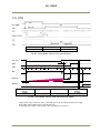
6.3.
Sync Mode
AD-130GE has two sensors inside and these two sensors can be synchronized or operated
independently. This mode selection is activated by ―Sync mode feature‖.
Factory default setting is ―Async‖.
Sync
Video out
Trigger in
mode
(Pixel format)
Sync
Trigger to sensor
1 operates sensor
Sensor 1 and 2
2.
can be set
Async
Input trigger to
independently
Sensor 1 and 2
independently
Functions
Sensor
Trigger input
Read out
(Partial, Smearless)
Settings to sensor 1
applies to sensor 2.
Sensor 1 and 2 can be
set independently
SYNC
RJ-45(GigE 1)
RJ-45(GigE 2)
Bayer(sensor1)
NIR(sensor2)
←
○
Triggered by GigE1
Output
Shutter
Partial scan
Smearless
Bayer
RGB
○
Monochrome
○
←
○
Follow the setting of
GigE 1
○
Follow the setting of
GigE 1
←
Functions
(Shutter,others)
Sensor 1 and 2
can be set
independently
ASYNC
RJ-45(GigE 1)
RJ-45(GigE 2)
Bayer(sensor1)
NIR(sensor2)
○
Bayer
RGB
○
○
Monochrome
○
○
○
○
○
In Sync mode, the trigger to Bayer also triggers to NIR.
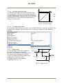
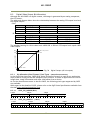
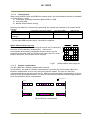
6.4.
Lens considerations
The AD-130GE is based on a dichroic prism, allowing precise separation of the visible (color)
and near-infrared parts of the spectrum.
Thanks to the compact design of the
NIR area
prism, C-mount lenses can be used with
Visible area
Focus Point
Focus point
this camera. For optimal performance it
is strongly advised to use lenses designed
for 3CCD cameras with the AD-130GE.
These lenses have minimal chromatic
aberration, thus allowing both the visible
and near-IR images to be in focus. Be
sure to select a lens that does not have
any built-in IR filtering as this will disrupt
the proper operation of the near-IR
image channel.
Fig 8 Focal points for Visible and NIR lights
15
AD-130GE
7.
Inputs and outputs interface
7.1.
Overview
All input and output signals pass through the GPIO (General Purpose Input and Output) module.
The GPIO module consists of a Look-Up Table (LUT – Cross-Point Switch), 2 Pulse Generators
and a 12-bit counter. In the LUT, the relationship between inputs, counters and outputs is
governed by internal register set-up.
C a m e ra 0
(In te rface #1 )
S o ftw a re
S o ftw a re
C a m e ra 1
(In te rface #2 )
S oftw a re
S oftw a re
F V A L1
LV A L1
D V A L1
E xp os ure A ctive 1
S o ftw are T rig g er 0
S oftw are T rig g er 1
T rig g er 2 / A ctio n 1
T rig g er 3 / A ctio n 2
F V A L2
LVA L2
DVA L2
E xp osure A ctive 2
S oftw a re T rig g er 0
S o ftw are T rig ge r 1
T rig g er 2 / A ctio n 1
T rig g er 3 / A ctio n 2
O p tic al In 1
O ptic a l In 2
T T L In 1
T T L In 2
F ram e S ta rt T rig g er
T ra ns fer S tart T rig g er
C am era 0
F ra m e S tart T rig g er
T ra ns fer S tart T rig g er
C am e ra 1
T T L O ut 1
O ptic al O ut 1
O ptic al O ut 2
C ro ss P o in t sw itch
T im e S tam p R eset
S e q u e nce T a ble R e set C am e ra 0
S e q u e nc e T a ble R eset C a m era 1
L V D S In
P uls e G e n erator
P u ls e G e n era to r 0 O u t
C le ar S o urc e
C le ar S o urc e
C le ar S o urc e
C le ar S o urc e
P u lse G e n erato r 1 O ut
P u ls e G e n erator 2 O u t
P u lse G e n erator 3 O u t
0
1
2
3
P u lse G e n e rato r 0
(2 0 b it C oun te r)
P u lse G ene rato r 1
(2 0 b it C oun te r)
P u lse G ene rato r 2
(2 0 b it C o u n te r)
P u lse G ene rato r 3
(2 0 b it C oun te r)
P u lse
G e n e ra to r
C lo ck (M H z)
(P ixe l C lo ck
51 .3 24 M H z)
C lo ck P re -scale r
(12b it C oun te r)
Fig. 9
Cross point switch
7.1.1
LUT (Cross Point Switch)
The LUT works as a cross-point switch which allows connecting inputs and outputs freely. The
signals LVAL_IN, DVAL_IN, FVAL_IN and EEN_IN all originate from the camera timing circuit.
On this diagram, Trigger 0 is used for exposure and Trigger 1 is used for Delayed Readout. The
Time Stamp Reset signal can reset the time stamp specified in GigE Vision Format. This signal
can be used when time stamps from several cameras connected are coincident with each other.
16
AD-130GE
The ―Sequence reset‖ resets the sequential settings. Outputs from the LUT described on the
right side show GPIO settings for LINE SELECTOR in the JAI Camera Control tool and inputs to
the LUT on the left side show GPIO settings for LINE SOURCE in the JAI Camera Control tool.
7.1.2
12-bit Counter
A camera pixel clock can be used as a source. The counter has a ―Divide by N‖, where N has the
range 1 through 4096, allowing a wide range of clock frequencies to be programmed. Setting
value 0 is bypass, setting value 1 is 1/2 dividing, and setting value 4095 is 1/4096 dividing. As
the pixel clocks for the AD-130GE are 51.324 MHz, the output frequency is varied from 51.324
MHz to 12.53 KHz.
7.1.3
Pulse Generators (0 to 3)
Each pulse generator consists of a 20-bit counter. The behavior of these signals is defined by
their pulse width, start point and end point.
The pulse generator signals can be set in either triggered or periodic mode.
In triggered mode, the pulse is triggered by the rising edge/falling edge/high level or low level
of the input signal. In periodic mode, the trigger continuously generates a signal that is based
on the configured pulse width, starting point and end point.
7.2.
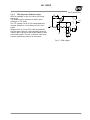
Opto-isolated Inputs/Outputs
The control interface of the C3 GigE Vision camera series has opto-isolated inputs and outputs,
providing galvanic separation between the camera’s inputs/outputs and peripheral equipment.
In addition to galvanic separation, the opto-isolated inputs and outputs can cope with a wide
range of voltages; the voltage range for inputs is +3.3V to +24V DC whereas outputs will handle
+5V to +24V DC.
Fig.10 Photo coupler
17
AD-130GE
7.2.1
Recommended External Input circuit diagram for customer
Fig.11
7.2.2
External Input Circuit、OPT IN 1 and 2
Recommended External Output circuit diagram for customer
+3.3V
Fig.12
External Output Circuit, OPT OUT 1 and 2
18
AD-130GE
7.2.3
Optical Interface Specifications
The relation of the input signal and the output signal through the optical interface is as follows.
Conditions for Input
Input Line Voltage Range
+3.3V ~ +24V
Input Current
6mA ~ 30mA
Minimum Input Pulse Width to Turn
0.5μs
ON
Output Specifications
Output Load(Maximum Current)
Minimum Output Pulse Width
Time Delay Rise
TDR
Rise Time
RT
Time Delay Fall
TDF
Fall Time
FT
Fig.13
7.3.
100mA
20μs
0.5μs ~ 0.7μs
1.2μs ~ 3.0μs
1.5μs ~ 3.0μs
4.0μs ~ 7.0μs
Optical Interface Performance
Input and output circuits
In the following schematic diagrams the input and output circuits for video and timing signals
are shown.
7.3.1
Iris Video output
This signal can be used for lens iris control in Continuous
mode. The signal is taken from the CCD sensor output
through the process circuit but as the reverse
compensation is applied, the signal is not influenced by
the gain settings. The video output is without sync. The
signal is 0.7 V p-p from 75 without termination.
This signal is taken from sensor 1 but it can be changed
by the register. In order to get this signal, DIP switch
DSW700 should be changed. Refer to 5.4.3.
+5V
0.1μ
2K2
1K
IRIS Video Out
1μ
DA
Fig.14 Iris video output
19
AD-130GE
800
100% Level
700
The
Anal og Out [ mV]
7.3.1.1
Iris Video input and output
The lens-iris video output level at pin 4 of the 12-pin
Hirose connector is 700 mV for 100% video output level.
iris video signal is taken after the gain circuit. However,
negative compensation is applied to the iris circuit, thus
gain setting has no influence for controlling auto iris
lenses. It is without sync.
the
CCD Out [ mV]
0
Fig.15
200
230
Iris Video output
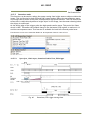
7.3.1.2
Iris video output select
As the factory default setting, the signal from AD-130GE #0(color) is used for iris control. The
setting can be changed in the following screen. This screen is effective if AD-130GE#0 is
selected.
7.3.2
Trigger input
An external trigger input can be applied to
pin 3 and 5 of 6-pin Hirose connector.
The input is AC coupled. To allow long pulses
the input circuit is designed as a flip-flop
circuit. The leading and trailing edges of the
trigger pulse activate the circuit.
The trigger polarity can be changed.
Trigger input level 4 V 2 V.
+5V
15K
HIROSE 6P
#3 & #5
●
0.1μ
75
●
1K2
39K
TTL
●
●
SW600
●
100K
0.001μ
Fig.16 Trigger circuit
20
1K
AD-130GE
7.3.3
EEN (Exposure Enable) output
XEEN is available on pin 4 of the 6-pin Hirose
connector.
The output can be selected as either open
collector or TTL level.
The TTL output circuit is 75 complementary
emitter followers. It will deliver a full 5 volt
signal.
Output level 4 V from 75. (No termination).
For the open collector, the maximum current is
120mA. But if current of more than 50mA is used,
use thicker cable. The use of thinner cable may
cause a malfunction due to its resistance.
180
1K
Open
Collector
1K
SW701
+5V
Push
Pull
10K
EEN
0.1
SW700
220
120
10
10
150
10K
Fig.17 EEN output
21
HIROSE
#9
AD-130GE
GPIO Inputs and outputs table
Pulse Generator 3
Pulse Generator 2
Pulse Generator 1
Camera 1
Sequence Table Reset
Camera 0
Sequence Table Reset
Time Stamp Reset
Line4 - Optical Out 2
Line 3 Optical Out 1
Transfer Start
TTL Out 1
Frame Start
Not Connected / Off
○
○
○
○
○
○
○
○
○
○
○
○
○
○
Line5 - Optical In 1
○
○
○
○
○
○
○
○
○
○
○
○
○
○
Line6 - Optical In 2
○
○
○
○
○
○
○
○
○
○
○
○
○
○
Line7 - TTL In 1
○
○
○
○
○
○
○
○
○
○
○
○
○
○
Line9 - TTL In 2
○
○
○
○
○
○
○
○
○
○
○
○
○
○
Line8 - LVDS In
○
○
○
○
○
○
○
○
○
○
○
○
○
○
Pulse Generator 0
○
○
○
○
○
○
○
○
○
○
×
○
○
○
Pulse Generator 1
○
○
○
○
○
○
○
○
○
○
○
×
○
○
Pulse Generator 2
○
○
○
○
○
○
○
○
○
○
○
○
×
○
Pulse Generator 3
○
○
○
○
○
○
○
○
○
○
○
○
○
×
Camera 0
Camera 1
Camera 0
Camera 1
Camera 0
Camera 1
Camera 0
Camera 1
Camera 0
Camera 1
Camera 0
Camera 1
Camera 0
Camera 1
○
○
○
○
○
○
○
○
○
○
○
○
○
○
○
○
○
○
○
○
○
○
○
○
○
○
○
○
○
○
○
○
○
○
○
○
○
○
○
○
○
○
○
○
○
○
○
○
○
○
○
○
○
○
○
○
○
○
○
○
○
○
○
○
×
×
○
○
○
○
○
○
○
○
○
○
○
○
×
×
○
○
○
○
○
○
○
○
○
○
○
○
×
×
○
○
○
○
○
○
○
○
○
○
○
○
×
×
○
○
○
○
○
○
○
○
○
○
○
○
×
×
○
○
○
○
○
○
○
○
○
○
○
○
×
×
○
○
○
○
○
○
○
○
○
○
○
○
×
×
○
○
○
○
○
○
○
○
○
○
○
○
×
×
○
○
○
○
○
○
○
○
○
○
○
○
×
×
○
○
○
○
○
○
○
○
○
○
○
FVAL1 (Interface#0)
×
×
×
×
○
×
×
×
×
×
○
○
○
○
LVAL1 (Interface#0)
×
×
×
×
○
×
×
×
×
×
○
○
○
○
DVAL1 (Interface#0)
×
×
×
×
○
×
×
×
×
×
○
○
○
○
Exposure Active1 (Interface#0)
×
×
×
×
○
○
○
×
×
×
○
○
○
○
FVAL2 (Interface#1)
×
×
×
×
○
×
×
×
×
×
○
○
○
○
LVAL2 (Interface#1)
×
×
×
×
○
×
×
×
×
×
○
○
○
○
DVAL2 (Interface#1)
×
×
×
×
○
×
×
×
×
×
○
○
○
○
Exposure Active2 (Interface#1)
×
×
×
×
○
×
×
○
○
○
○
Source Signal
(Cross Point Switch Input)
Software Trigger 0
Software Trigger 0
Software Trigger 1
Software Trigger 1
Software Trigger 2
Software Trigger 2
Software Trigger 3
Software Trigger 3
Software
Software
Action 1
Action 1
Action 2
Action 2
Trigger
Source
Line 1
Transfer Start
Pulse Generator 0
Pulse
Generator
Selector
Line
Selector
Camera 1
Trigger
Selector
Frame Start
Selector
(Cross Point
Switch Output)
Camera 0
7.4.
○
Line
Source
22
○
×
Pulse
Generator
Clear
Source
×
×
○
○
AD-130GE
7.5.
Configuring the GPIO module
7.5.1
Input /Output Signal Selector
GPIO is used to determine which signal is assigned which terminal. For the details, please refer
to Register Map, Digital I/O, Acquisition and Trigger Control and Pulse Generator.
Line Selector
Line Source
7.5.2
Pulse generators (20 bit x 4)
There are 4 pulse generators (designated 0 through 1) that can be used to create various timing
scenarios by programming start point, endpoint, length and repeats.
Start Point
End Point
Length
Fig.18 Pulse waveform
Example of the setting
The following drawing is an example of settings.
FVAL is used for the input of a pulse generator 0 and the clock, after the rising edge of FVAL,
counts 100 clocks for the high period of the pulse and 102 clocks for the pulse length.
As 2400 is for Clock Pre-scaler, the output of the 12 bit counter is 25 KHz, which is 40µs.
23
AD-130GE
Thus, pulse generator 0 creates a 4 ms pulse.
Pulse Generator Clear = 4: Rising Edge
Pulse Generator 0
(FVAL )
IN
Clock IN
Clock Source=Pixel Clock ( 60MHz)
Clock Pre-scaler = 2400 ⇒ 25KHz
0
1
2
3
99 100 101 102 103
1/25KHz = 40µs
Start Point = 0
Pulse Generator 0
OUT
(GPIO Port 1 )
End Point = 100
1
2
Length = 102
1
Repeat counter: 0 to 255
=0: Continuously repeated
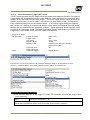
The following shows JAI SDK Camera Control Tool for setting Pulse Generators.
7.5.3
GPIO interface in GenICam standard
Outputs from Cross Point Switch are displayed in 3 sectors in GenICam standard.
Inputs to Cross Point Switch are displayed as Source in each sector.
(1)
[Acquisition Control] - [Trigger Selector] - [Trigger Source]
:Select the trigger source for Frame Start and Transfer Start Trigger
(2)
[Digital IO Control] - [Line Selector] - [Line Source]
:Select signal inputs and outputs for camera I/F
(3)
[Pulse Generators] - [Pulse Generator Selector] - [Pulse Generator Clear Source]
: Select the signal source for CLEAR input to Pulse Generator
7.5.4
Change polarity
The polarity of AD-130GE is positive as the default setting.
This can be changed in each sector as follows.
(1)
[Acquisition Control] - [Trigger Selector] - [Trigger Activation] and
[Trigger Source Inverter]
In the AD-130GE, [Trigger Activation] and [Trigger Source Inverter] are changed
simultaneously.
24
AD-130GE
[Trigger Activation] =―Rising Edge‖& [Trigger Source Inverter] =―False‖ settings are
default.
The default setting can be changed to [Trigger Activation] =―Falling Edge‖& [Trigger
Source Inverter] = ―True‖.
If ―Rising Edge‖ is set, the rising edge is effective input.
If ―Falling Edge‖ is set, the falling edge is effective.
(2)
[Digital IO Control] - [Line Selector] - [Line Inverter]
―False‖is default setting. This can be changed to ―True‖.
If ―False‖ is set, the signal selected in Line Source (Line Mode=Output) is directly
connected to Line Selector.
If ―True‖ is set, the signal selected in Line Source (Line Mode=Output) is connected to
Line Selector after its polarity is reversed.
。
(3) [Pulse Generators] - [Pulse Generator Selector] - [Pulse Generator Inverter(Polarity)]
―False‖ is deafault and can be changed to ―True‖.
If ―False‖ is set, the signal selected in Pulse Generator Clear Source is directly
connected to Pulse Generator Selector.
If ―True‖ is set, the signal selected in Pulse Generator Clear Source is connected to
Pulse Generator Selector after its polarity is reversed.
7.5.5
The restrictions to use TTL In I/F in the AD-130GE
If the polarity of TTL I/F in the AD-130GE is changed, the initialization is executed in the
camera.
If the source for the same selector item of Camera 0 and Camera 1 is assigned TTL In1 and TTL
In2 respectively, the initialization is executed without any problem.
However, if the source for the same selector item of Camera 0 and Camera 1 is assigned the
same TTL In and the polarity is changed, there is some restriction as the initialization is
executed using the Camera 0 polarity setting as the reference.
It is recommended to use a different sources for Camera 0 and Camera1.
25
AD-130GE
Example of the restriction if the frame start trigger for Camera 0 and Camera 1 is set to TTL In1
① P o sitive P ulse
R ising E d ge
Recognized
② N e g ative P u lse
R ising E d ge
Recognized
T T L In 1
I/F
C am era 0
F ram e S tart
[T rig g er A c tivatio n] Setting
= “R isin g E d g e”
① P o sitive P ulse
or
Initialize
② N e g ative P u lse
T T L In 1 I/F
Initialized by Camera 0
① P o sitive P ulse
F alling E d ge
Recognized
② N e g ative P u lse
F alling E d ge
C am era 1
F ra m e S ta rt
[T rig g er A c tivatio n] Setting
= “F allin g E d g e”
Not recognized
[Restriction]
In Sync Mode = Async, TTL In1 I/F is initialized using Trigger Activation of Camera 0 as the reference. If the trigger set in Trigger
Activation is applied to Camera 1 first, Camera 1 cannot recognize the trigger and misses one frame. (Case ②)
Fig. 19.
Restriction by polarity setting
7.5.6
Caution when the software trigger is used
The AD-130GE has the following restriction when using the software trigger.
1) The input port of GPIO, Camera 0 and Camera 1 have software trigger 0 to 3, respectively.
However, the output port of GPIO has only one software trigger 0 to 3.
Therefore, the function is described in the figure 21.
It is recommended to use a different software trigger for Camera 0 and Camera 1.
Example for Frame Start Trigger
Host PC
AD -130GE
TG
Camera 0
Frame Start
Camera 0
GPIO
Camera 0
Software Trigger 0
Command
Software Trigger0
I/F
Trigger
Camera 1
Camera#0
Camera1
Software
Trigger
Frame
Start0
Command
Frame Start
Trigger
[
Activation ]
=― Rising Edge ‖
26
Camera 1
AD-130GE
If Software trigger 0 is selected as the trigger source for Frame Start Trigger of Camera 0 and
Camera 1, the command for Camera 0 and command for Camera 1 are mixed. Therefore, Software
trigger 0 command for Camera 0 and Camera 1 are applied to both Camera 0 and Camera 1, and the
function does not operate properly.
Fig. 20
Software Trigger
setting restriction
2) Action Command
In the action command of AD-130GE, Software 2 and 3 are used as action commands
and sent to the selected source.
If the source is set to Action 1, for instance, it is changed to Software trigger 2 in
the camera control tool.
Action 1 => Use Software Trigger 2
Action 2 => Use Software Trigger 3
3) ―Trigger Source = Software‖ in Frame Start and Transfer Start
For Frame Start and Transfer Start in the AD-130GE, ―Trigger Source = Software‖
can be set and Software command 0 and software command 1 can be sent.
Frame Start / Trigger Software command => Use Software Trigger 0
Transfer Start / Trigger Software command => Use Software Trigger 1
27
AD-130GE
7.6.
GPIO programming examples
7.6.1
GPIO Plus PWC shutter
Example: 10µs unit pulse width exposure control (PWC). Pixel clock is 51.324MHz.
513 clocks (613-100) equal 10µs.
Feature
Value
c)Acquisition and
Trigger selector Trigger Mode
ON
Trigger controls
JAI Acquisition and
JAI Exposure
Pulse width control
Trigger Control
Mode
Pulse Generators
Pulse Generator Pulse Generator 0 Selector
Line 5 =OPT IN 1
selector
Clock Choice
1 = Pixel Clock
(51.324MHz)
Counter Dividing Value
0 = Pass through
Length Counter 0
1000 Clocks
Start point Counter 0
100 Clocks
Repeat Count 0
1
End point Counter 0
613 Clocks
Counter Clear 0
Rising Edge
Trigger source
pulse generator 0
C a m e ra 0
(In te rfa c e # 1 )
S o ftw a re
S o ftw a re
C a m e ra 1
(In te rfa c e # 2 )
S o ftw a re
S o ftw a re
FVA L1
LVA L1
DVA L1
E xp o s u re A c tive 1
S o ftw a re T rig g er 0
S o ftw a re T rig g er 1
T rig g e r 2 / A ctio n 1
T rig g e r 3 / A ctio n 2
FVA L2
LVA L2
DVA L2
E xp o s u re A c tive 2
S o ftw a re T rig g e r 0
S o ftw a re T rig g e r 1
T rig g er 2 / A ctio n 1
T rig g er 3 / A ctio n 2
O p tic a l In 1
O p tic a l In 2
T T L In 1
T T L In 2
F ra m e S ta rt T rig g er
T ra n s fe r S ta rt T rig g e r
C a m e ra 0
F ra m e S ta rt T rig g er
T ra n s fe r S ta rt T rig g e r
C a m e ra 1
TTL O ut 1
C ro s s P o in t s w itc h
O p tic a l O ut 1
O p tic a l O ut 2
T im e S tam p R es e t
S e q u e nc e T a b le R e s et C a m e ra 0
S e q u e nc e T a b le R e s et C a m e ra 1
L V D S In
P u ls e G e n era to r
C le a r S o u rc e 0
C le a r S o u rc e 1
C le a r S o u rc e 2
C le a r S o u rc e 3
P u ls e G e n era to r 0 O u t
P u ls e G e n era to r 1 O u t
P u ls e G e n e ra to r 2 O u t
P u ls e G e n e ra to r 3 O u t
P u ls e G e n e ra to r 0
(2 0 b it C o u n te r)
P u ls e G e n e ra to r 1
(2 0 b it C o u n te r)
P u ls e G e n e ra to r 2
(2 0 b it C o u n te r)
P u ls e G e n e ra to r 2
(2 0 b it C o u n te r)
P u ls e
G e n e ra to r
C lo c k (M H z)
(P ixe l C lo c k
5 1 .3 2 4 M H z )
C lo c k P re -sc a le r
(1 2 b it C o u n te r)
Fig.21 Pulse Generator Timing Example 1
28
AD-130GE
7.6.2
Internal Trigger Generator
Example: Create a trigger signal and trigger the camera.
Feature
c)Acquisition and
Trigger
Trigger Mode
Trigger controls
selector
Pulse Generators
Pulse
Pulse Generator 0 Selector
Generator
selector
Clock Choice
Counter Dividing Value
Length Counter 0
Start point Counter 0
Repeat Count 0
End point Counter 0
Clear activation
Trigger source
C a m e ra 0
(In te rfac e #1 )
S o ftw a re
S o ftw a re
C a m e ra 1
(In te rfac e #2 )
S o ftw a re
S o ftw a re
FVA L1
LVA L1
DVA L1
E xp os u re A c tive 1
S o ftw a re T rig g er 0
S o ftw a re T rig g er 1
T rig g er 2 / A ctio n 1
T rig g er 3 / A ctio n 2
FVA L2
LVA L2
DVA L2
E xp os u re A c tive 2
S o ftw a re T rig g er 0
S o ftw a re T rig g e r 1
T rig g er 2 / A ctio n 1
T rig g er 3 / A ctio n 2
O p tic a l In 1
O p tic a l In 2
T T L In 1
T T L In 2
C ro s s P o in t s w itc h
F ra m e S ta rt T rig g er
T ra n s fe r S ta rt T rig g er
C a m e ra 0
F ra m e S ta rt T rig g er
T ra ns fe r S ta rt T rig g er
C a m e ra 1
O p tic a l O ut 1
O p tic a l O ut 2
T im e S tam p R es e t
S e q u e nc e T a ble R e s et C a m e ra 0
S e q u e nc e T a ble R e s et C a m e ra 1
L V D S In
P u ls e G e n era to r
C le ar S o urc e 0
C le ar S o urc e 1
C le ar S o urc e 2
C le ar S o u rc e 3
P u ls e G e n e rato r 0
(2 0 b it C o u n te r)
P u ls e G e n e rato r 1
(2 0 b it C o u n te r)
P u ls e G e n e rato r 2
(2 0 b it C o u n te r)
P u ls e G e n e rato r 2
(2 0 b it C o u n te r)
C lo c k P re -sc ale r
(1 2 b it C o u n te r)
Fig.22
1 = Pixel Clock (50MHz)
2499 (51324000/2500)
1000 Clocks
100 Clocks
0
293 Clocks
Off
pulse generator 0
TTL O ut 1
P u ls e G e n era to r 0 O u t
P u ls e G e n era to r 1 O u t
P u ls e G e n era to r 2 O u t
P u ls e G e n era to r 3 O u t
P u ls e
G e n e ra to r
C lo c k (M H z)
(P ixe l C lo c k
5 1 .3 24 M H z)
Value
ON
Pulse Generator 0 timing Example 2
29
AD-130GE
8.
8.1.
Video Signal Output
Sensor layout
blank
1348
Read Out
(Vertical)
2
2
Optical Black Lines
978
976
Active Pixels
1296 (H)x966(V)
966
Optical Black Lines
8
1660 Clock
4
12
40
1296
dummy
308
blank
Read Out(Horizontal)
In the GigE Vision Format, only Active Pixel Area is output and the area of dummy and reserved
is not output. If the OB transfer mode is set ON, OB parts of 8 pixels on the top and 16 pixels on
the right are output.
Fig.23. Sensor layout and Video output image
Note for output image:
The output area depends on the settings of Pixel Format as well as OB transfer Enable.
The available display image is indicated by ―Width Max‖ and ―Height Max‖ in the control tool.
The following table shows relations mentioned on the above.
OB Transfer Enable =―False‖
Width Max
Height Max
BayRG8,BayRG10,BayRG12,
BayRG10_Packed,BayRG12_Packed,
Mono8, Mono10, Mono12,
Mono10_Packed,Mono12_Packed
RGB8_Packed,
BGR10V1_Packed, BGR10V2_Packed
OB Transfer Enable =―True‖
Width Max
Height Max
1296
966
1312
970(Note1)
1292(Note2)
962(Note2)
-
-
Note1: This is if JAI Partial Scan is set to ―False‖. This will be 966, if JAI Partial Scan is set to ―True‖
Note2: In case of RGB output, 2 pixels each on both sides are not read out.
30
AD-130GE
8.2.
Partial scan (JAI Partial Scan ON)
Partial scan allows higher frame rates by reading out a smaller center portion of the image,
reducing vertical resolution. This is particularly useful when inspecting objects that do not fill
the whole height of the image. In order to activate this function, Fast Dump register should be
ON.
Fast-dump period
Normal scan period
Fast-dump period
Full scan
Partial Scan
Fig.24 Conceptual drawing for partial scan
The partial scan mode for AD-130GE is variable. The first line and the last line to be read out
can be set. For Bayer color, the start line should set on an odd line and the last line is set so
that the height is an even number. It should be noted that if an even start line is set, the pixel
format is automatically changed to GB pixel format.
The variable scan readout is connected with the ROI settings.
1. If ROI is set, these settings are applied to the partial scan settings.
2. If the multi ROI is used, the smallest number of the line and the largest number of the line
define the partial scan area.
3. In the case of sequence trigger, it is the same as for multi ROI. The smallest line and the
largest line define the partial scan.
In order to execute the partial scan, the JAI Partial Scan should be ON.
1. The start line and end line
if ROI is set
Offset Y1
Offset Y
Height
2,3 The start line and end line
if Multi ROI is set.
Height 1
ROI 1
ROI 2
ROI
Height 3
ROI 3
Height 4
ROI 4
ROI 5
Height 1+2+3+4+5 ≦ 966
Fig.25 Partial scan
31
Height 2
Height 5
AD-130GE
8.3.
Digital Video Output (Bit Allocation)
Although the AD-130GE is a digital camera, the image is generated by an analog component,
the CCD sensor.
The table and diagram below show the relationship between the analog CCD output level and
the digital output.
Color
CCD out
Analog Signal *
Bayer10bit
RGB24bit、Bayer8bit
Black
0mV
33.5LSB
8LSB
150mV
700mV
890LSB
222LSB
800mV
1023LSB
255LSB
173mV↑
IR
CCD out
Analog Signal *
IR 10bit
IR 8bit
Black
0mV
33.5LSB
8LSB
200mV
700mV
890LSB
222LSB
800mV
1023LSB
255LSB
230mV↑
The standard setting for 10-bit video level is 890 LSB. A 200 mV CCD output level equals 100%
video output.
1023
White Clip Level
100% Level
Digital Out [LSB]
890
32
0
Black Level
25
Analog Signal [mV]
700 800
Fig. 26 Digital Output (10 bit output)
8.3.1
Bit Allocation (Pixel Format / Pixel Type) – (monochrome sensor)
In the GigE Vision Interface, GVSP (GigE Vision Streaming Protocol) is used for an application
layer protocol relying on the UDP transport layer protocol. It allows an application to receive
image data, image information and other information from a device.
As for the monochrome sensor in the AD-130GE, the following pixel types supported by GVSP
are available.
With regard to the details of GVSP, please refer to the GigE Vision Specification available from
the AIA (www.machinevisiononline.org).
8.3.1.1
1 Byte
GVSP_PIX_MONO8 (8bit)
2 Byte
3 Byte
Y0
Y1
Y2
0 1 2 3 4 5 6 7 0 1 2 3 4 5 6 7 0 1 2 3 4 5 6 7
8.3.1.2
GVSP_PIX_MONO10
1 Byte
2 Byte
(10bit)
3 Byte
4 Byte
Y0
Y0
Y1
Y1
0 1 2 3 4 5 6 7 8 9 X X X X X X 0 1 2 3 4 5 6 7 8 9 X X X X X X
32
AD-130GE
8.3.1.3
GVSP_PIX_MONO10_PACKED (10 bit)
1 Byte
2 Byte
3 Byte
4 Byte
Y0
Y3
Y1
Y2
2 3 4 5 6 7 8 9 0 1 X X 0 1 X X 2 3 4 5 6 7 8 9 2 3 4 5 6 7 8 9 0 1 X X 0 1 X X 2 3 4 5 6 7 8 9
8.3.1.4
GVSP_PIX_MONO12 (12 bit)
1 Byte
2 Byte
3 Byte
4 Byte
Y0
Y0
Y1
Y1
0 1 2 3 4 5 6 7 8 9 10 11 X X X X 0 1 2 3 4 5 6 7 8 9 10 11 X X X X
8.3.1.5
GVSP_PIX_MONO12_PACKED (12 bit)
1 Byte
2 Byte
3 Byte
4 Byte
Y0
Y1
Y2
Y3
4 5 6 7 8 9 10 11 0 1 2 3 0 1 2 3 4 5 6 7 8 9 10 11 4 5 6 7 8 9 10 11 0 1 2 3 0 1 2 3 4 5 6 7 8 9 10 11
Connector
RJ-45_2
Value
Mono8
Mono10
Mono10 Packed
Mono12
Mono 12 Packed
8.3.2
Bit Allocation (Pixel Format / Pixel Type) – (Bayer mosaic color sensor)
In the GigE Vision Interface, GVSP (GigE Vision Streaming Protocol) is used for an application
layer protocol relying on the UDP transport layer protocol. It allows an application to receive
image data, image information and other information from a device.
As for the Bayer mosaic color sensor in the AD-130GE, the following pixel types supported by
GVSP are available.
With regard to the details of GVSP, please refer to the GigE Vision Specification available from
the AIA.
8.3.2.1
GVSP_PIX_BAYRG8 “BayerRG8”
Odd Line
1 Byte
2 Byte
3 Byte
R0
G1
R2
0 1 2 3 4 5 6 7 0 1 2 3 4 5 6 7 0 1 2 3 4 5 6 7
Even Line
1 Byte
2 Byte
3 Byte
G0
B1
G2
0 1 2 3 4 5 6 7 0 1 2 3 4 5 6 7 0 1 2 3 4 5 6 7
33
AD-130GE
8.3.2.2
GVSP_PIX_BAYRG10 “Bayer RG10”
Odd Line
1 Byte
2 Byte
3 Byte
4 Byte
R0
R0
G1
G1
0 1 2 3 4 5 6 7 8 9 X X X X X X 0 1 2 3 4 5 6 7 8 9 X X X X X X
Even Line
1 Byte
2 Byte
3 Byte
4 Byte
G0
G0
B1
B1
0 1 2 3 4 5 6 7 8 9 X X X X X X 0 1 2 3 4 5 6 7 8 9 X X X X X X
8.3.2.3
GVSP_PIX_BAYRG12 “Bayer RG12”
Odd Line
1 Byte
2 Byte
3 Byte
4 Byte
R0
R0
G1
G1
0 1 2 3 4 5 6 7 8 9 10 11 X X X X 0 1 2 3 4 5 6 7 8 9 10 11 X X X X
Even Line
1 Byte
2 Byte
3 Byte
4 Byte
G0
G0
B1
B1
0 1 2 3 4 5 6 7 8 9 10 11 X X X X 0 1 2 3 4 5 6 7 8 9 10 11 X X X X
8.3.2.4
GVSP_PIX_BAYRG10_Packed (Bayer10bit, Packed output)
Odd Line
2 3
4
5
6
R0
7 8 9
0
1 X X 0
1 X X 2
G0
3 4
5
6
7
8
9
Even Line
G1
B0
2 3 4 5 6 7 8 9 0 1 X X 0 1 X X 2 3 4 5 6 7 8 9
8.3.2.5
GVSP_PIX_BAYRG12_Packed (Bayer12bit, Packed output)
Odd Line
R0
G0
4 5 6 7 8 9 10 11 0 1 2 3 0 1 2 3 4 5 6 7 8 9 10 11
Even Line
G1
B0
4 5 6 7 8 9 10 11 0 1 2 3 0 1 2 3 4 5 6 7 8 9 10 11
8.3.2.4
1 Byte
GVSP_PIX_RGB8_PACKED “RGB 8Packed”
2 Byte
3 Byte
4 Byte
R0
G0
B0
0 1 2 3 4 5 6 7 0 1 2 3 4 5 6 7 0 1 2 3 4 5 6 7
34
AD-130GE
8.3.2.5
GVSP_PIX_RGB10V1_PACKED “RGB 10V1 Packed”
1 Byte
2 Byte
3 Byte
4 Byte
R0
G0
B0
R0
G0
B0
0 1 0 1 0 1 X X 0 1 2 3 4 5 6 7 0 1 2 3 4 5 6 7 0 1 2 3 4 5 6 7
8.3.2.6
GVSP_PIX_RGB10V2_PACKED “RGB 10V2 Packed”
1 Byte
2 Byte
3 Byte
4 Byte
R0
G0
B0
0 1 2 3 4 5 6 7 8 9 0 1 2 3 4 5 6 7 8 9 0 1 2 3 4 5 6 7 8 9 X X
Connector
RJ-45_1
Value
BAYRG8
BAYRG10
BAYRG12
BAYRG10_Packed
BAYRG12_Packed
RGB8
RGB10V1Packed
RGB10V2Packed
Note: If the start line of ROI is set at even line, GB pixel format is automatically output instead
of RG pixel format.
35
AD-130GE
8.4.
Video timing
8.4.1
Horizontal Timing
The horizontal timing for Continuous mode, full frame and partial scan are shown below.
This is common for both Bayer color imager and monochrome IR imager.
1 Clock =51.324MHz (19.48ns)
1CLK: 1 Pixel clock period
OB: Optical black
LVAL is HIGH in the period of optical black and effective video periods
DVAL is HIGH in the effective video period
Fig.27 Horizontal Timing
36
AD-130GE
8.4.2
Vertical Timing
The vertical timing for Continuous mode and full frame scan are shown below.
This is common for both Bayer color imager and monochrome IR imager
If JAI Partial Scan = False,
1L = 1660 clock (32.344μs)
1L : 1 LVAL period OB: optical black
FVAL is HIGH in the optical black and effective video periods
LVAL is always output
DVAL is output during the effective lines
This timing chart shows camera timing. The output through GigE interface is only effective lines.
Fig.28 Vertical Timing
37
AD-130GE
8.4.3
Partial Scan Vertical Timing
The following chart shows the vertical timing of partial scanning in the continuous mode. The
horizontal timing for partial scan is the same as full scan. This is common for Channel 1 (visible,
color) and Channel 2 (near-IR)
If JAI Partial Scan = True,
1L : 1LVAL period OB: Optical Black
1L = 1660 clock (32.344μs)
Fig.29 Vertical Timing for partial scan
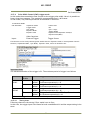
How to calculate total line number and frame rate on variable partial scan mode
Partial scan Offset Y
Height
0 line to 958 line
8 lines to 966 lines
Total lines = ① + ② + ③ + ④ + ⑤ + ⑥
Where,
① OB period in the upper part of the frame= 4L
② Fast dump period for the upper part= Round up {(4+(Offset) - 1)/5}
③ Read out lines = Height + G
G=1, if Height is odd, G=0, if Height is even.
④ Fast dump period for the lower part=
Round up {((966 –(OffsetY)- (Height) +2))/5)
⑤ Even adjustment for total line=
⑤=1, If ①+②+③+④+⑥ is odd and ⑤=0, if ①+②+③+④+⑥ is even.
⑥ Dummy transfer period = 5L
Frame rate (fps) = Horizontal Frequency / Total lines
where, Horizontal Frequency
30.918KHz
38
AD-130GE
Calculation example
Reference
JAI Partial Scan
Height
Offset Y
Full Line
False
966
0
Full Line
Center 2/3 Partial
Center 1/2 Partial
Center 1/4 Partial
Center 1/8Partial
Center 8 Line
True
True
True
True
True
True
966
644
482
242
120
8
0
160
242
362
422
478
39
Total
Line
982
FPS
31.484
978
720
590
398
302
212
31.613
42.941
52.403
77.682
102.380
145.84
AD-130GE
9.
Network configuration
9.1.
For details of the network settings, please refer to the “Getting Started
Guide” supplied with the JAI SDK.
GigE Vision Standard Interface
The AD-130GE is designed in accordance with the GigE Vision standard. Digital images are
transmitted over Cat5e or Cat6 Ethernet cables. All camera functions are also controlled via
the GigE Vision interface.
The camera can operate in Continuous mode, providing an endless stream of images. For
capturing individual images related to a specific event, the camera can also be triggered. For
precise triggering, it is recommended to use a hardware trigger applied to the Hirose 12-pin
connector. It is also possible to initiate a software trigger through the GigE Vision interface.
However, when using a software trigger, certain latency inherent to the GigE interface must be
expected. This latency, which manifests itself as jitter, greatly depends on the general
conditions and traffic on the GigE connection. The frame rate described in this manual is for
the ideal case and may deteriorate depending on conditions.
When using multiple cameras (going through a switch and/or a single path) or when operating
in a system with limited transmission bandwidth the Delayed Readout Mode and Inter-Packet
Delay functions can be useful.
9.2.
9.2.1
9.2.2
9.2.3
Equipment to configure the network system
PC
The PC used should have the following performance or better
1) Recommended CPU
: Core2 Duo 2.4GHz or better,
Better than Core2 Extreme
2) Recommended memory
: 2Gbyte or more
3) Video card
: Better than PCI Express Bus Ver.1.0 x16
VRAM should be better than 256MByte, DDR2
4) Other
: The resident software should not be used
Cables
GigEVision configures the system by using 1000BASE-T.
In the market, CAT5e (125MHz), CAT6 (250MHz) and CAT7 (600MHz) cables are
available for 1000BASE-T. There are crossover cables and straight through cables
available. Currently, as most equipment
complies with Auto MDI/MDI-X, please use straight through cables. (Among crossover
cables, a half crossover type exists, which the Ethernet will recognize as 100BASE-T).
Network card (NIC)
The network card should comply with 1000BASE-T and also have the capability of
JUMBO FRAMES. When the jumbo frame size is set at a larger number, the load on the
CPU will be decreased. Additionally, as the overhead of the packet is decreased, the
transmission will have more redundancy.
40
AD-130GE
JAI confirms the following network cards.
NIC
PCI-X Bus
Manufacture Type
Intel
PRO/1000MT
Server Adapter
Intel
PRO/1000MT Dual Port
Server Adapter
Intel
PRO/1000GT Quad
Port
Server Adapter
Intel
PRO/1000PT
―
Server Adapter
Intel
Pro/1000 CT
―
Desktop adaptor
Intel
Gigabit ET2 Quad
port
―
Server Adapter
Intel
Gigabit ET Dual port
―
Server Adapter
Intel
Gigabit EF Dual port
―
Server Adapter
9.2.4
9.3.
PCI-Express
Bus
( x1 )
( x1 )
( x4 )
( x4 )
( x4 )
32bit or 64bit
33/66/100/133 MHz
32bit or 64bit
33/66/100/133 MHz
32bit or 64bit
66/100/133 MHz
2.5Gbps uni-directional
5Gbps bi-directional
2.5Gbps uni-directional
5Gbps bi-directional
10Gbps uni-directional
20Gbps bi-directional
10Gbps uni-directional
20Gbps bi-directional
10Gbps uni-directional
20Gbps bi-directional
Hub
It is recommended to use the metal chassis type due to the shielding performance.
As the hub has a delay in transmission, please note the latency of the unit.
Recommended Network Configurations
Although the AM-800GE and AB-800GE conforms to Gigabit Ethernet (IEEE 802.3) not all
combinations of network interface cards (NICs) and switches/routers are suitable for use
with the GigE Vision compliant camera.
JAI will endeavor to continuously verify these combinations, in order to give users the
widest choice of GigE components for their system design.
9.3.1
For details of the network settings, please refer to the “Getting Started
Guide” supplied with the JAI SDK.
Guideline for network settings
To ensure the integrity of packets transmitted from the camera, it is recommended to
follow these simple guidelines:
1. Whenever possible use a peer-to-peer network.
2. When connecting several cameras going through a network switch, make sure it is
capable of handling jumbo packets and that it has sufficient memory capacity.
3. Configure inter-packet delay to avoid congestion in network switches.
4. Disable screen saver and power save functions on computers.
5. Use high performance computers with multi-CPU, hyper-thread and 64-bit CPU,
etc.
6. Only use Gigabit Ethernet equipment and components together with the camera.
7. Use at least Cat5e and preferably Cat6 Ethernet cables.
8. Whenever possible, limit the camera output to 8-bit.
41
AD-130GE
9.3.2 Video data rate (network bandwidth)
The video bit rate for the AD-130GE in Continuous mode is:
Model
Pixel Type
Frame Rate
AD-130GE
MONO8
31Frame/s
MONO10_PACKED
31Frame/s
MONO12_PACKED
MONO10
31Frame/s
MONO12
31Frame/s
BAYRG8,(BAYGB8)
BAYRG10 Packed,
31Frame/s
(BAYGB10 Packed)
BAYRG12 Packed,
(BAYGB12 Packed)
31Frame/s
BAYRG10,(BAYGB10)
BAYRG12,(BAYGB12)
RGB8
29.5rame/s
BGR10V1, BGR10V2
22.1Frame/s
Packet (Packet 1500)
328Mbit/s
492Mbit/
655Mbit/s
328Mbit/s
492Mbit/
655Mbit/s
940Mbit/s
940Mbit/s
In the case of using Jumbo Frames (16K), the packet data will be improved by 2%.
Note for setting packet size
The packet size is set to 1476 as the factory default. Packet size can be modified in the GigE
Vision Transport Layer Control section of the camera control tool (see below). For AD-130GE,
users may enter any value for the packet size and the value will be internally adjusted to an
appropriate, legal value that complies with the GenICam standard. Thus, the actual packet
size may be different than the value entered by the user.
Caution: do not set the packet size larger than the maximum setting available in the NIC or
switch to which the camera is connected. Doing so will cause output to be blocked.
The following table shows possible packet size on each pixel format.
Pixel format
Possible packet size
8bit
36 + 8 x n
10bit_Packed,
36 + 12 x n
12bit_Packed
10bit,12bit
36 + 16 x n
RGB 8bit
36 + 24 x n
Note for calculation of Data Transfer Rate
Setting parameter
Item
Image Width
Image Height
Unit
[pixels]
[pixels]
Symbol
A
B
Bits per Pixel
[bits]
C
[fps]
[Bytes]
D
E
[packets]
G
[Mbit/s]
J
Frame Rate
Packet Size
Number of Packets (including Data Leader & Trailer
Packet)
DataTransfer Rate
42
232 ≤ n ≤ 1348
174 ≤ n ≤ 1011
174 ≤ n ≤ 1011
58 ≤ n ≤ 337
AD-130GE
Fixed value
Item
Data Leader Packet Size
Data Trailer Packet Size
Unit
[Bytes]
[Bytes]
value
90
62
Formula to calculate Data Transfer Rate
J={90+62+(E+18)*(G-2)}*8*D/1000000
Where,
G=ROUNDUP{A*B*C/8/(E-36)}+2
The following table shows Bits per Pixel which depends on the pixel format.
Pixel format
MONO8
MONO10
MONO10Packed
MONO12
MONO12Packed
BAYRG8
BAYRG10
BAYRG12
RGB8
RGB10V1Packed
RGB10V2Packed
Calculation example: AD-130GE
Bit
8
16
12
16
12
8
16
16
24
32
32
Pixel type Mono8
Item
Image Width
Image Height
Bits per Pixel
Frame Rate
Packet Size
Number of Packets (including Data Leader & Trailer
Packet)
Transfer Data Rate
Unit
[pixels]
[pixels]
[bits]
[fps]
[Bytes]
Symbol
A
B
C
D
E
[packets]
G
[Mbit/s]
J
Setting
1296
966
8
31.484
1428
G=ROUNDUP{(1296x966x8/8/(1428-36))+2=900+2=902
J={90+62+(1428+18)x(902-2))x8x31.484/1000000=328 Mbit/s
9.3.3
Simplified calculation (Approximate value)
A simple way to calculate the approximate data transfer rate is the following.
Transfer data = image width (pixel) x Image Height (pixel) x depth per pixel
(depending on the pixel format) x frame rate / 1,000,000 (convert to mega bit)
In the case of the AD-130GE with the full image and Mono 8bit pixel format;
The data transfer rate = 1296 x 966 x 8 x 31.484 / 1000000 = 315 Mbit/s
43
AD-130GE
9.3.4
Note for 100BASE-TX connection
In order to use 100Mbps network, 100BASE-TX and Full Duplex are available. Half Duplex
cannot be used.
In the case of connecting on 100BASE-TX, the maximum packet size should be 1500
bytes.
In the case the of connecting on 100BASE-TX, the specifications such as frame rate,
trigger interval and so on described in this manual cannot be satisfied.
Pixel Type
MONO8, BAYRG8, BAYGB8
MONO10_PACKED,MONO12_PACKED
MONO10, MONO12,BAYRG10,
BAYGB10,BAYRG12, BAYGB12
RGB8_Packed
RGB10V1_Packed,RGB10V2_Packed
Frame rate at Full Frame scan[fps]
Approx. 7
Approx. 5
Approx. 3.5
Approx. 2.5
Approx. 2
Note: The above frame rates are based on approx. 70Mbps of total data.
9.4.
9.4.1
GigE camera connecting examples
Using a switching hub for 1 port
All cameras and NIC belong to the same subnet
The accumulated transfer rate for all cameras should be within 800Mbps
The packet size and the packet delay should be set appropriately in order for
the data not to overflow in the switching hub.
44
AD-130GE
9.4.2
Connecting a camera to each port of a multi-port NIC
9.4.3
9.4.3.1
This is the example for using a 4-port NIC
The pair of the connecting camera and the NIC constructs one subnet. As for
the IP configuration, it is appropriate to use the persistent IP.
In this case, each camera can use the maximum 800Mbps bandwidth.
However, the load for the internal bus, CPU and the application software
become heavy, so a powerful PC will most likely be required.
The data transfer for multiple cameras
If delayed readout is not used in continuous mode
The packet delay should be set larger. The data traffic is controlled by the
buffer of the hub. It is necessary to check the buffer value of the unit.
45
AD-130GE
9.4.3.2
If delayed readout is not used in trigger mode
9.4.3.3
The packet delay should be set larger. The data traffic is controlled by the
buffer of the hub. It is necessary to check the buffer value of the unit.
If delayed readout is used
The packet delay should be set smaller, and the packet delay trigger controls
the data traffic. If the camera has a pulse generator, it can control the data
traffic.
46
AD-130GE
10. Functions (Conforming to GenICam SFNC 1.3)
This section describes naming of GenICam SFNC ver.1.3.
AD-130GE uses the feature names specified in GenICam SFNC ver.1.3 but some functions
are not implemented. AD-130GE also provides feature names used in previous JAI cameras.
10.1.
Acquisition function
Before using trigger and exposure controls, various acquisition controls must be set. The
operation of the camera depends on the interrelationship of all three feature sets.
Trigger Mode
[JAI Acquisition
Transfer Start]
Acquisition Start
Internal
Stream
Control
Stream Control
Acquisition Stop
Acquisition Abort
Trigger
Selector
[Acquisition
Start]
Acquisition
Status
Acquisition Status Control
Acquisition
State
Control
Trigger
Selector
[Acquisition
Stop]
Acquisition Mode
Acquisition Frame count
Trigger Selecctor
[Frame Start]
Exposure Control
Internal
Exposure
Control
Trigger Selector
[Exposure Start]
Trigger Selector
[Exposure End]
Acquisition Frame Rate
Acquisition Control
Trigger / Exposure Control
Active
Fig.30
Acquisition control, Trigger/Exposure control work flow
10.1.1
Basic image acquisition flow
The basic commands for acquiring images are as follows:
Acquisition mode
To determine the number of the frame to be captured
Trigger Selector
Acquisition Start Trigger
Select if the acquisition start is controlled
externally
Acquisition End
Select if the acquisition end is controlled externally
Trigger Selector
Frame start
Select if the acquisition of the frame is controlled
externally.
47
AD-130GE
Exposure mode
To set the exposure method
The flow of these commands is shown below.
The following drawings are based on the conditions that the Acquisition mode is Single
and the Trigger selector is Frame Start.
If the acquisition start is set at ON (The acquisition is controlled externally)
Acquisition
Start
Command
Executed
Acquisition
Start
Trigger
Acquisition
Trigger Wait
Acquisition
Status
Acquisition
Start
Trigger
Frame Start
Trigger
Frame Start
Trigger Wait
Acquisition Active
Acquisition
Trigger Wait
If the acquisition start is set at OFF (The acquisition is controlled internally)
Acquisition
Start
Command
Executed
Acquisition
Status
Frame Start
Trigger
Frame Start
Trigger Wait
Frame Start
Trigger
Acquisition Active
Frame Start
Trigger Wait
The following sections provide the details for each command set.
10.1.2
Acquisition mode
The AD-130GE has three settings for capturing images.
Single frame
AcquisitionStart command outputs one frame. Then the acquisition is stopped.
Continuous
AcquisitionStart command outputs frames until AcquisitionEnd is initiated.
10.1.2.1
Single Frame
In single frame mode, executing the AcquisitionStart command causes one frame to
be captured. After one frame is captured, this operation is automatically stopped.
In order to restart the capture, it is necessary to input the AcquisitionStart
command again. BlockID is not reset until AcquisitionEnd is input and is incremented
when the AcquisitionStart command is called.
◆ Normal single frame operation
1) AcquisitionStart command is input
2) AcquisitionActive becomes ―TRUE‖ (accepts capture)
48
AD-130GE
3) 1 frame is output
4) AcquisitionActive becomes ―FALSE‖ (stop capturing)
ExposureActive
FrameActive
CCD Readout
Stream
Active
AcquisitionStart
AcquisitionStatus
Acquisition
Trigger
Wait
Acquisition
Active
Fig.31
AcquisitionTriggerWait
Single frame timing
This drawing shows a case where the trigger is ―OFF‖. If the trigger is ON,
FrameActive becomes ―TRUE‖ on the different timing of AcquisitionActive.
◆ Forcing acquisition to stop
While AcquisitionActive is ―TRUE‖, if AcquisitionEnd or AcquisitionAbort is
initiated, AcquisitionActive becomes ―FALSE‖ (stop capturing).
10.1.2.2
Continuous mode
In this mode, when the AcquisitionStart command is set, the image is continuously
output at the current frame rate. This is the default setting for the AD-130GE.
1)
2)
3)
4)
5)
6)
AcquisitionStart command is input
AcquisitionTriggerWait becomes effective
AcquisitionActive becomes “TRUE”
Images begin outputting continuously
AcquisitionEnd command is sent
AcquisitionActive becomes “FALSE”. At this moment, the output stops.
ExposureActive
FrameActive
Frame 1
Frame N
CCD Readout
Stream Active
AcquisitionStart
AcquisitionStatus
Acquisition
Trigger
Wait
AcquisitionActive
Fig.32
AcquisitionStop
Acquisition
Trigger
Wait
Continuous timing
This drawing shows a case where the trigger is ―ON‖. If the trigger is OFF,
FrameActive becomes ―TRUE‖ at the same timing as AcquisitionActive.
49
AD-130GE
10.2.
Trigger Control
10.2.1
TriggerSelector(TriggerMode)
This is the function to set the trigger operation. This will set how to control the output
and the exposure.
Frame Start
Transfer Start
10.2.1.1
Trigger
Stream
Set the frame start externally
Set the stream start externally
Acquisition
This is the trigger function to control the output. This controls AcquisitionStart and
AcquisitionEnd. A description of the configuration process is as follows:
AcquisitionStart trigger: Set whether the capture start is to be controlled
externally or not.
TriggerMode On:
After AcquisitionStart command is input, input the
signal selected by AcquisitionStart trigger as the trigger,
and make AcquisitionActive effective.
TriggerMode Off:
AcquisitionStart command is input. It makes
AcquisitionActive effective regardless of
AcquisitionStart trigger.
AcquisitionEnd trigger:
TriggerMode On:
TriggerMode Off:
10.2.1.2
Set whether the end of the capture is to be
controlled externally or not.
While AcquisitionActive is effective, input the signal
selected by AcquisitionEnd as the trigger, and make
AcquisitionActive invalid.
AcquisitionStart command is input. It makes
AcquisitionActive invalid regardless of the trigger
source.
Exposure
These commands are used for setting the exposure control.
FrameStart is used for trigger input.
If ExposureMode is set to Timed or TriggerWidth except OFF, the combination of the
ExposureMode setting and FrameStart setting will determine the type of exposure
and whether triggering is OFF or ON.
The following table shows the combination and the operation.
50
AD-130GE
TriggerSelector
Frame
Start
Operation
ExposureMode
OFF
Timed
TriggerWidth
Previous JAI
trigger name
(for reference)
Trig OFF(Free run)
No Exposure Control
Trigger
OFF
OFF
Trig OFF(Free run)
Exposure Control
Is possible
Trigger
OFF
ON
Trig On
EPS
Trig OFF(Free run)
No Exposure Control
Trig On
Trigger
OFF
PWC
OFF or
ON
OFF
ON
FrameStart trigger: Set whether the start of the frame is to be controlled
externally or not.
TriggerMode On:
While AcquisitionActive is effective and ExposureMode is
set at Timed or TriggerWidth, start exposure using the
signal selected by FrameStart trigger.
TriggerMode Off:
While AcquisitionActive is effective, self-running
operation takes place.
10.2.2
Triggersoftware
This is one of the trigger sources and is the software trigger command.
This has one command signal to each of the 6 items of TriggerSelector.
To use this function, TriggerSource must be set at TriggerSoftware.
10.2.3
Triggersource
The following signals can be selected as the trigger signal source.
10.2.4
TriggerActivation
This determines the behaviour of the trigger.
RisingEdge:
Initiate at the signal rising edge
FallingEdge:
Initiate at the signal falling edge
LevelHigh:
Initiate during the signal high level
LevelLow:
Initiate during the signal low level
51
AD-130GE
Note: When TriggerWidth is used, TriggerActivation should be set at either LevelHigh
or LevelLow.
RisingEdge
FallingEdge
LevelHigh
LevelLow
Timed
○
○
×
×
TrigegrWidth
×
×
○
○
Timed-JAI Pre-Dump
○
○
×
×
10.3.
Exposure Control
This is the function to manage the exposure settings.
10.3.1
Exposure Mode
The exposure mode can be selected from the following choices.
Timed:
The exposure time is to be set in microseconds.
If FrameStart in TriggerSelector is“OFF”, the exposure is
controlled in Free Run.
If FrameStart in TriggerSelector is “ON”, this functions as the
EPS mode.
Note: JAI Pre-Dump can be available by using TriggerOption.
TriggerWidth:
This mode controls the exposure time by the pulse width.
If FrameStart in TriggerSelector is “OFF”,
The camera operates in Free Run.
If FrameStart in the TriggerSelector is “ON”, this functions as
the PWC mode.
The following is the table for the combination of ExposureMode and TriggerControl
and its function.
TriggerSelector
Frame
Start
Operation
ExposureMode
OFF
OFF or
ON
Timed
OFF
ON
TriggerWidth
OFF
ON
10.3.2
Previous JAI
trigger name
(for reference)
Trig OFF(Free run)
Exposure controllable
Trig OFF(Free run)
Exposure control is
possible
Trig On
Trigger
OFF
Trigger
OFF
Trig OFF(Free run)
No Exposure control
Trig On
Trigger
OFF
PWC
ExposureTime
This is effective only if ExposureMode is set to“Timed”.
This command can set the exposure time.
The setting can be done in 1μs / step.
Minimum:
11.49μs
Maximum:
31.76msec
52
EPS
AD-130GE
10.3.3 ExposureAuto
This is auto exposure control function and is effective only in the “Timed”mode.
The reference video level is controlled by JAI AGC Reference.
ExposureAuto includes OFF, Once and Continuous modes.
The following detailed settings are aslo possible.
ExposureAuto speed:
The reaction speed can be controlled
ExposureAuto Max:
Set the maximum exposure time
ExposureAuto Min:
Set the minimum exposure time
GainAutoReference:
Set the reference video level for operation
10.4.
ActionControl
ActionControl is used to activate the specific functions of multiple cameras on the same
network at the same time. For instance, it can be used to trigger multiple cameras at
the same time.
ActionControl appears as two inputs (Action 1, Action 2) and is connected with 6 Triggers,
CounterReset of the counter, CounterTrigger and Timer.
If ActionControl is used, the input source to the trigger should be set to Action 1 or
Action 2 in advance.
10.4.1
ActionDeviceKey
Set the same value to cameras which are operated at the same time.
10.4.2
ActionSelector
Select Action 1 or Action 2.
10.4.3
ActionGroupMask
Set the mask value for grouping Action 1 operation.
10.4.4
ActionGroupKey
Set the key (value) to operate Action 1.
10.5.
Operation Mode
AD-130GE has the setting for the exposure timing when the trigger pulse is applied and the
following 9 operation modes and OB transfer and ROI modes.
1
2
3
4
5
6
7
8
9
Trigger mode
Trigger mode
Trigger mode
Trigger mode
Trigger mode
Trigger mode
Continuous mode
Edge Pre-Select Trigger
Pulse Width Control Trigger
Reset Continuous Trigger
Sequence EPS
Delayed readout EPS
Smearless
OB transfer mode
ROI mode
53
AD-130GE
10.5.1
The exposure timing when the trigger pulse is input
10.5.1.1 Auto-detect LVAL-sync / async accumulation
This function replaces the manual setting found in older JAI cameras. Whether accumulation is
synchronous or asynchronous in relationship to LVAL depends on the timing of the trigger input.
When a trigger is received while FVAL is high (during readout), the camera works in
LVAL-synchronous mode, preventing reset feed-through in the video signal. There is a
maximum jitter of one LVAL period from issuing a trigger to accumulation start.
When an external trigger is received during FVAL low, the camera works in LVAL-asynchronous
(no delay) mode.
This applies to both Pre-Select (PS) trigger and Pulse Width trigger (PW) modes.
Ext. trigger
(1)
(2)
(3)
FVAL
(1) In this period camera executes trigger at next LVAL (prevents feed-through noise)
(2) Avoid trigger at FVAL transition (+/- 1 LVAL period), as the function may randomly switch
between "next LVAL" and "immediate".
(3) In this period camera executes trigger immediately (no delay)
Fig. 33 Auto-detect LVAL sync /a-sync accumulation
10.5.1.2
Relation between the external trigger mode and LVAL Sync/Async
Operation :
Exposure Mode
(JAI)
Edge pre-select
Pulse-width
control
RCT Mode
Sequential
EPS trigger
Delayed readout
EPS trigger
Delayed readout
PWC trigger
Smearless
Enable
LVAL SYNC
LVAL
ASYNC
False
True
False
True
○
×
×
×
○
○
○
○
-
×
○
False
True
False
True
False
True
×(note1)
×
○
×
×
×
○
○
○
○
○
○
Note 1: In the sequence trigger mode, each entry in the sequence can be set to its own
exposure time and gain. Therefore, the LVAL sync operation does not function.
Please arrange for the trigger input timing to occur during FVAL LOW (LVAL
Async).
54
AD-130GE
10.5.2
Continuous mode
For applications not requiring asynchronous external triggering, this mode should be used for
continuous operation.
To use this mode
Acquisition mode
Set function:
Trigger mode
Sync mode
Exposure Mode
Pixel Format
:Continuous
:OFF
:Sync / Async
:Timed
:8bit、10bit、12bit
Other functions
10.5.3
Edge Pre-Select (EPS) trigger mode
An external trigger pulse initiates the capture, and the exposure time (accumulation time) is
the fixed shutter speed set by registers. The accumulation can be LVAL synchronous or LVAL
asynchronous. The resulting video signal will start to be read out after the selected shutter
time.
To use this mode:
Acquisition mode
Set function:
:Frame Start
:ON
:Sync / Async
:Timed
:Exposure time/Exposure time(us)/
Exposure time(Raw)
Trigger mode
Sync mode
Exposure Mode
Exposure time
Input:
Other functions
External Trigger
Trigger Source
This function can be set by selecting Edge pre-select in Exposure mode of JAI Acquisition Control.
However, Acqusition Mode, Sync Mode, Exposure Time, and so on should be set.
55
AD-130GE
Important Note:
The trigger minimum active period is 2L and the minimum interval of the trigger is shown
below.
SYNC Mode Smearless Minimum trigger interval (Line)
Enable
SYNC
False
LVAL
Frame interval in continuous operation + Larger
Mode=
ASYNC Exposure Time(Raw) between Color and IR+ 5L
SYNC
LVAL
① If Exposure Time(Raw) range is 3L to (Frame
SYNC
interval in continuous operation(L) - 1L)
Frame interval in continuous operation +
Difference between Color and IR + 5L
② If JAI Partial Scan is set at True and Exposure
Time(Raw) range is Frame interval in continuous
operation(L) to 982L
SYNC
Mode=
ASYNC
True
LVAL
ASYNC
False
LVAL
ASYNC
LVAL
SYNC
Frame interval in continuous operation(L)
+(Difference between Color and IR exposure time)+
5L + ( Smaller exposure time between color and IR Frame interval in continuous operation(L) + 1L)
Smear less period[196L]+ 1 + (Larger exposure time
between color and IR)+ Frame interval in continuous
operation(L) + 6L
Frame interval in continuous operation(L) + Exposure
Time(Raw) + 5L
① If Exposure Time(Raw) range is 3L to (Frame
interval in continuous operation(L) - 1L)
Frame interval in continuous operation(L) + 5L
② If JAI Partial Scan is set to True and Exposure
Time(Raw) range is Frame interval in continuous
operation (L) to 982
Frame interval in continuous operation(L) + Exposure
Time(Raw) – Frame interval in continuous
operation(L) + 6L
True
LVAL
Smearless period[196L]+ 1 +Exposure Time(Raw)+
ASYNC Frame interval in continuous operation (L)+ 6L
1) LVAL SYNC/ASYNC can be selected automatically.
2) Frame interval of full frame in continuous operation is 982L and if JAI partial scan is set
to True, please refer to 8.4.3 Partial Scan Vertical Timing for the frame interval.
3) If Smearless Enable is set to True, only LVAL Async is available.
10.5.3.1 Timing chart
Following charts are examples if Sync mode is set to Sync and in full frame operation.
If Sync mode is set to Sync, the timing of trigger input is the same for both camera #0 and #1.
The exposure time can be set individually but the output timing of the video output is the
same.
56
AD-130GE
Note: 2.8L to 3.8L after the exposure end of the longest exposure.
1 LVAL = 1660 clock (32.344μs)
Fig.34 Edge Pre-select LVAL asynchronous
Ext. Trigger
FVAL
LVAL
Exposure Period
EEN
t2
Exposure
t1
t3
DATA out
t1(Exposure start delay)
6.03μs
t2
2.8L to 3.8L
t3(Data output delay)
10.8L to 11.8L
Fig.35 Edge Pre-select LVAL asynchronous details
57
AD-130GE
Note: 2.8L after the exposure end of the longest exposure
Fig.36 Edge Pre-select LVAL synchronous
Ext. Tri g
FVAL
LVAL
EEN
Exposure Period
t2
Exposure
t1
t3
DATA out
t1(Exposure start delay)
0.1L ~ 1.1L(3 ~ 35.2μs)
t2
2.8L
t3(Data output delay)
10.8L
Fig.37 Edge Pre-select LVAL synchronous details
Note for setting Exposure Time
For instance, if the exposure time for the color channel is 1/31 sec and that of the monochrome
IR channel is 1/87,000 sec, the picture quality of the monochrome IR channel may not be
acceptable due to CCD’s operational principle. Accordingly, in EPS mode, each channel’s
exposure time should be set the same. If it is necessary to set different exposure times, please
confirm the picture quality in advance of usage.
58
AD-130GE
10.5.4
Pulse Width Control (PWC) trigger mode
In this mode the accumulation time is equal to the trigger pulse width. Here it is possible to
have a long time exposure. The maximum recommended time is <60 frames.
In PWC mode, only LVAL asynchronous accumulation is effective.
To use this mode:
Acqusition mode
Set function:
:Frame Start
:ON
:Sync / Async
:Trigger Width
:Exposure time/Exposure time(us)/
Exposure time(Raw)
Trigger mode
Sync mode
Exposure Mode
Exposure time
Input:
Other functions
External Trigger
Trigger Source
This function can be set by selecting Pulse width control in Exposure mode of JAI Acquisition Control.
However, Acquisition Mode, Sync Mode, Exposure Time, and so on should be set.
Important Note:
The minimum duration of the trigger is 2L. The minimum period of trigger is as follows.
SYNC Mode
SYNC Mode
=SYNC
Smearless
Enable
False
Minimum Trigger interval (Line)
LVAL
(Trigger Pulse width: Min.2L) + Frame interval in
ASYNC continuous operation(L) + 4L
True
LVAL
(Trigger Pulse width:Min.197L+2L) + Frame interval in
ASYNC continuous operation(L) + 4L
SYNC Mode False
LVAL
(Trigger Pulse width: Min.2L) + Frame interval in
=ASYNC
ASYNC continuous operation (L) + 4L
True
LVAL
(Trigger Pulse width : Min.197L+2L) + Frame interval
ASYNC in continuous operation(L) + 4L
Pulse-width trigger is available only in LVAL Async accumulation.
10.5.4.1 Timing chart
Following charts are the timing if Sync mode is set to Sync.
In this case, the trigger input is the same for both camera#0 and #1 and the output timing is the
same.
59
AD-130GE
t1
0.5L
t2
2.8L ~ 3.8L
t3
0.2L
Fig.38 Pulse Width Control LVAL asynchronous
Ext. Tri g
t4
FVAL
LVAL
Exposure Period
EEN
t2
Exposure
t1
t3
DATA out
t1(Exposure start
delay
6.03μs
t2
t3(Output delay)
2.8L ~ 3.8L
10.8L ~ 11.8L
t4(Exposure end
delay)
17.45μs
Fig.39 Pulse Width Control LVAL asynchronous details
In PWC mode, when ―Smearless ON ‖ is selected, the actual accumulation time is the trigger
pulse width minus Smearless active period (197L+2L).
If the trigger pulse width is shorter than 199L, the exposure is not active.
60
AD-130GE
10.5.5
Smearless mode
This function can be used to reduce the smear coming from bright areas or objects within the
image. This is effective for both EPS and PWC trigger modes. Before the accumulation starts,
any charge that is stored in the pixel is dumped by a high-speed transfer. This can reduce the
smear that is visible directly above a bright object in the image, but the smear showing below
the object is unaffected.
At the falling edge of the trigger pulse the high speed transfer starts. This period is 6.34ms
which is 196L. Thereafter the residual charge in the horizontal CCD register is read out in 1L
and the new exposure starts. This function is available for both full scan and partial scan.
This function can be set if Smearless Enable in JAI Acquisition Control is set at True.
10.5.5.1
Sync=Sync, LVAL Async, Smearless Enable=True, EPS trigger
Fig. 40
Smearless, EPS trigger timing chart
61
AD-130GE
10.5.5.2
Sync Mode=Sync, LVAL Async, Smearless Enable=True, PWC trigger
Fig 41.
PWC timing chart with Smearless ON
62
AD-130GE
10.5.6
Reset Continuous Trigger (RCT) mode
The RCT mode operates like EPS (edge pre-select) mode with smearless function. An external
trigger pulse will immediately stop the video read out, reset and restart the exposure, then
operate as normal mode until the next trigger. After the trigger pulse is input, a fast dump
readout is performed. In the AD-130GE, this period is 6.34ms which is 196L. The exposure
time is determined by the pre-set shutter speed. If no further trigger pulses are applied,
the camera will continue in normal mode and the video signal is not output. The fast dump
readout has the same effect as ―smearless readout‖. Smear appearing above highlight areas
is reduced for the trigger frame. The Reset Continuous Trigger mode makes it possible to use
triggering in conjunction with a lens with video controlled iris.
To use this mode:
Acqusition mode
Set function:
Pre-dump mode
:Frame Start
:ON
:Sync / Async
:Timed
:Exposure time/Exposure time(us)/
Exposure time(Raw)
:ON
Other functions
External Trigger
Trigger Source
Trigger mode
Sync mode
Exposure Mode
Exposure time
Input:
This function can be set by selecting RCT mode in Exposure mode of JAI Acquisition Control.
However, Acqusition Mode, Sync Mode, Exposure Time, and so on should be set.
Important notes on using this mode
The minimum duration of the trigger is 2 LVAL. The minimum period of the trigger input
is the following.
Sync mode:
Smearless period(196L)+1+ Exposure Time(RAW) + Frame interval in
Async
continuous operation(L) + 6L
Note: If the next trigger is input during the output of transfer signal, this output signal is
immediately stopped and thrown away by the High Speed Transfer operation.
63
AD-130GE
Min.
2L
Ex t . Tr i g 1
F VAL
L VAL
Hi g h S peed
Tr a ns f er
Smearless (197L)
S UB
SG
Expos ur e
Per i od
EEN
Co n t i n u o u s
Co n t i n u o u s
Da t a
Da t a
T r i g g e r e d Da t a
D A T A OUT
DVAL
Fig.42 Reset Continuous Trigger
10.5.7
Sequential Trigger Mode (EPS)
This mode allows the user to define a preset sequence of up to 10 images, each with its own
ROI, Shutter and Gain values. As each trigger input is received, the image data with the
preset sequence is output as described below.
Trigger
Sequence
Operation
Sequence 1
Sequence 2
Sequence 3
Sequence 4
Fig.43 Sequential Trigger Mode
10.5.7.1 Setting parameters
Following parameters in Sequence control should be adjusted.
(1)
Sequence Mode:
Sequence Mode = On is to set to Sequential EPS Trigger mode.
(2)
Sequence Repetition Count:(applicable value:0~255)
This sets how many times the sequence is repeated.
If the last Sequence Repetition Count is completed, the sequence table is set tothe Last
Sequence setting. If further trigger pulses are input, the settings for the Last Sequence, are
repeated until Reset Sequence is input.
Sequence Repetition Count = 0 will cause the sequence to repeat indefinitely.
64
AD-130GE
(3)
Last Sequence:(applicable value:1~10)
To determine how many sequences out of sequences 1 to 10 are executed as one
consecutive sequence.
(4)
Sequence Selector:
In the Sequence Selector, there are 10 sequence tables.
Each Sequence has 8 setting parameters such as Sequence ROI Size X and Y、Sequence ROI Offset
X and Y、Sequence Exposure Raw、Sequence Master Gain Raw、and Repeat Count in Each Step.
In the Sequential EPS Trigger, the order to execute is from Sequence 1 settings.
(5)
Repeat Count in Each Step:(applicable value:1~255)
After the Sequence table is repeated as many as numbers set in ―Repeat Count in Each
Step”, the next sequence table is activated.
(6)
Reset Sequence command:
If the Reset Sequence is applied during sequence operation, the sequence operation is
initialized to start at sequence 1.
(7)
Sequence Table Reset input:
The Sequence Table Reset is available from GPIO output port.
This initializes the sequence operation by hardware trigger.
The following is how the settings appear in the GUI.
65
AD-130GE
10.5.7.2
Initial settings
The following are the default settings.
Sequence Control
Off
0
1
Sequence
Camera 0
Sequence Mode
Sequence Repetition Count
Last Sequence
ROI
Sequence Selector
Size
Offset
Exposure Time
Raw
Master Gain
Raw
Repeat Count
in Each Step
X
Y
X
Y
Sequence 1
1296
966
0
0
982
0
1
Sequence 2
1296
966
0
0
982
0
1
Sequence 3
1296
966
0
0
982
0
1
Sequence 4
1296
966
0
0
982
0
1
Sequence 5
1296
966
0
0
982
0
1
Sequence 6
1296
966
0
0
982
0
1
Sequence 7
1296
966
0
0
982
0
1
Sequence 8
Sequence 9
Sequence 10
1296
1296
1296
966
966
966
0
0
0
0
0
0
982
982
982
0
0
0
1
1
1
Sequence Control
Off
0
1
Sequence
Camera 1
Sequence Mode
Sequence Repetition Count
Last Sequence
ROI
Sequence Selector
Size
Offset
Exposure Time
Raw
Master Gain
Raw
Repeat Count
in Each Step
X
Y
X
Y
Sequence 1
1296
966
0
0
982
0
1
Sequence 2
1296
966
0
0
982
0
1
Sequence 3
1296
966
0
0
982
0
1
Sequence 4
1296
966
0
0
982
0
1
Sequence 5
1296
966
0
0
982
0
1
Sequence 6
1296
966
0
0
982
0
1
Sequence 7
1296
966
0
0
982
0
1
Sequence 8
Sequence 9
Sequence 10
1296
1296
1296
966
966
966
0
0
0
0
0
0
982
982
982
0
0
0
1
1
1
Caution:
1. In the Sequential EPS Trigger, LVAL sync operation is not available as the different
exposure time and gain in each sequence table can be set. The trigger should be applied in
LVAL Async timing.
2. In order to change values in the Sequence Table are changed, image capture must be
stopped.
10.5.8
Delayed Readout EPS and PWC Modes
This mode can be used to delay the transmission of a captured image. When several cameras
are triggered simultaneously and connected to the same GigE interface, it allows the cameras
to be read out in sequence, preventing congestion.
The image data is not transmitted directly by the Frame Start Trigger and is stored in the
memory located at the Ethernet Interface. By the leading edge of the Transfer Start Trigger,
66
AD-130GE
the image data is output.
AD-130GE has up to 6 memories to store, and the stored image data can be output at the
consecutive timing of Transfer Start Trigger.
After the stored image is transmitted by Transfer Start Trigger, as the memory has the space,
it is possible to store new images by Frame Start Trigger.
This mode is available if Acquisition mode is set at ―Continuous‖.
This mode can work in EPS mode and PWC mode. This is not available for Sequence Trigger.
①
②
⑤
④
③
⑥
Frame Start
Trigger
Exposure
GigE Memory
①
②
③
④
⑤
⑥
①
②
③
②
③
④
⑤
⑥
Transfer Start
Trigger
①
GigE output
Fig.44
④
⑥
⑤
Delayed readout concept drawing
The image is captured the following settings;
Frame start =ON, Trigger mode = ON and Exposure mode = Timed or Trigger Width
Then, the image is moved to ―Delayed Readout Mode‖,
If Trigger Selector is set to Transfer Start.
10.5.9
Multi ROI mode (Multi Region of Interest)
In this trigger mode, up to 5 ROIs located on one image can
be output by one trigger input. By using this mode, the
data stream can be smaller.
Each ROI can be overlapped.
Please note that if the accumulated data size is bigger than
the data size of 1 frame, the frame rate will be reduced.
Also accumulated heights for each ROI should be within 966
lines.
ROI 2
ROI
1
ROI 5
ROI
3
ROI 4
Fig.45 Multi mode concept
10.5.9.1 Setting parameters
In order to execute Multi ROI operation, it is necessary to set ROI mode and ROI size and offset.
ROI Mode:
Can be set 1 to 5. This sets the number of ROIs. For multi ROI operation, this should be set
from 2 to 5. A total of 5 ROI can be set.
ROI Selector:
67
AD-130GE
In ROI Selector, there is ROI 1 to 5 and each has Width, Height, Offset X and Offset Y
settings.
The following is how the settings appear in the GUI.
If ROI Mode is set to 1, only one ROI can be set.
In order to use Multi ROI, it should be set at 2 or more. A maximum of 5 ROIs
can be set. The size for each ROI can be set by ROI selector.
10.5.9.2
Initial parameters
Camera 0
1
Height
Offset X
Camera 1
1
Height
Offset X
ROI Mode
ROI Selector
Width
Offset Y
Width
ROI 1
1296
966
0
0
1296
966
0
0
ROI 2
1296
966
0
0
1296
966
0
0
ROI 3
1296
966
0
0
1296
966
0
0
ROI 4
ROI 5
1296
1296
966
966
0
0
0
0
1296
1296
966
966
0
0
0
0
Offset Y
10.5.10 Optical Black transfer mode
It is possible for the user to decide whether the optical black (OB) portion of the image will be
transferred or not. The optical black part can be used for black reference in the application
software. Setting register 0xA41C turns the optical black transfer ON or OFF. The default
condition is OFF.
OB Transfer Mode OFF
OB Transfer Mode ON
Full
1
JAI Partial
Scan
1296
1
5
5
970
970
1
1296
1
1296 1312
16 horizontal
pixels and 4
vertical
pixels are
added.
1024
1040
16
horizontal
pixels are
added
68
AD-130GE
10.6.
Operation Mode and Functions matrix
10.6.1.
Sync Mode = SYNC
AD-130GE #0
Sensor
Bayer(channel1)
Trigger Input
Trigger 1 : Valid
Smear
Mode
Shutter Partial
less
1
2
3
4
5
6
7
Continuous
Yes
Edge
Pre-select
Yes
(EPS)
Pulse
Width
Not
Control applicable
(PWC)
RCT
—
Sequentia
Yes
l EPS
Delayed
Readout
No
EPS
Delayed
Readout
No
PWC
AD-130GE #1
Monochrome(channel2)
Trigger 2 : Invalid
Smear
Shutter Partial
less
Auto Iris
output
←
No
Yes(*2)
(note2)
Yes
No
Yes
Yes
Yes
Yes
←
←
No
Yes
Yes
Not
applicable
←
←
No
—
—
—
—
—
—
Yes
Yes
Yes
Yes
Yes
No
Yes
Yes
Yes
←
←
No
Yes
Yes
No
←
←
No
(note1)
Note 1: ―←” means that the setting depends on channel 1.
Note 2: Video signal for auto iris uses the output can be selected in Iris Signal Output Mode.
Note 3: If Sync mode is set to Sync, RCT is not available.
10.6.2
SYNC Mode = Async
Sensor
Bayer(channel1)
Monochrome(channel2)
Auto Iris
Trigger Input
Trigger 1 : Valid
Trigger 2 : Invalid
output
Smear
Smear
(note2)
Mode
Shutter Partial
Shutter Partial
less
less
Continuous
1
Yes
Yes
No
Yes
Yes
No
Yes (*2)
2
3
4
5
6
7
Edge
Pre-select
Yes
(EPS)
Pulse
Width
Not
Control applicable
(PW)
RCT
Yes
Sequentia
Yes
l EPS
Delayed
Readout
Yes
EPS
Delayed
Readout
No
PWC
Yes
Yes
Yes
Yes
Yes
No
Yes
Yes
Not
applicable
Yes
Yes
No
Yes
Automatically
ON
Yes
Yes
Automatically
ON
Yes(*2)
Yes
Yes
Yes
Yes
Yes
No
Yes
Yes
Yes
Yes
Yes
No
Yes
Yes
No
Yes
Yes
No
Note 1: ―←” means that the setting depends on channel 1.
Note 2: Video signal for auto iris uses the signal can be selected in Iris Signal Output Mode.
69
AD-130GE
11.
11.1.
Other functions
Basic functions
The AD-130GE is based on a dichroic prism, allowing precise separation of the visible (color)
and near-infrared parts of the spectrum into two separate channels. The visible (color) channel
is referred to as Channel 1 and the near-infrared channel is referred to as Channel 2. Channel 1
and 2 can be configured to operate separately or synchronously. When operating separately
each channel can be triggered independently.
The AD-130GE can operate in Continuous (free-run) mode or in triggered modes.
The variable partial scan mode provides higher frame rates at lower vertical resolution.
11.1.1 2CCD optical assembly
The dichroic prism incorporated in the AD-130GE separates the visible (color) part of the
spectrum into a wavelength band from 400nm to 650nm (Channel 1) and the near-IR part into a
band ranging from 760 nm to 1000 nm (Channel 2).
The figure below shows the concept of the separation into visible and near-IR bands.
Visible light
Channel 1
Near-IR
Channel 2
Imager 2
Fig.46
Conceptual diagram for 2CCD prism optics
11.1.2
Electronic shutter
The AD-130GE has three shutter modes: programmable exposure, GenICam standard Exposure
Time Abs, and auto shutter.
Exposure Time Abs (GenICam Standard)
This is a function specified in the GenICam standard.
The shutter speed can be entered as an absolute exposure time in microseconds (μs) in register
address 0xA018. The entered absolute time (Time Abs) is then converted to programmable
exposure (PE) value inside the camera.
The calculating formula below shows the relationship between the PE values used by the
70
AD-130GE
camera for the different readout modes.
Due to rounding down of calculations, some discrepancies may occur.
The relation between PE value and Time Abs
Normal readout
PE= INT (Exposure time) µs / (1660/51324000)
(Note: INT means round down.)
Note:The minimum value in normal readout is 16µs.
In the AD-130GE, previous settings are also available in JAI Acquisition Control.
Programmable Exposure
Exposure time can be controlled in 1 L unit (32.344µs) from 0L to 982L. As the overhead of 0.4L
is added, the actual shutter time is from 0.4L to 982L in the range from 0.4L to 982L. 982 L is
the shutter OFF. The actual shutter speed for each operation mode is shown below.
Mode
Continuous,
EPS/RCT
PWC
Note:
Read Out
Full, Partial
Minimum shutter speed
11.49µs (=1/87000s)
Maximum shutter speed
1 Frame
Full, Partial
32.344µs x 2L+11.49µs( 0.4L)=
60 Frames (2 seconds)
76.111µs (approx. 1/13,000s)
In Pulse Width mode, the minimum trigger pulse width must be >2LVAL.
Auto shutter
Auto shutter works in the range of 1/31 to 1/325 sec depending on the incoming light.
GPIO in combination with Pulse Width trigger
More precise exposure time can be obtained by using GPIO in combination with Pulse Width
mode. The clock generator and counter can be programmed in very fine increments.
11.1.3
Shading correction
The AD-130GE features a shading correction circuit that can be used for reducing shading
resulting from illumination, lens vignetting or prism shading caused by lenses with a wide
output aperture.
The shading correction circuit divides the image into horizontal and vertical fields, and adjusts
these regions in relationship to the image center.
In the internal memory, factory data is stored. When the shading correction is ON, factory data
is loaded.
If it is OFF, the calibration can be activated and the result can be stored in the user area for
reuse. Each channel is treated separately. The shading correction works with all pixel formats,
raw Bayer color, RGB color and monochrome.
71
AD-130GE
11.1.4
White balance
When using the RGB 24-bit and RGB 30-bit output mode, the white balance function is available.
It can be used in 3 ways:
1) Continuous (tracking) Automatic White Balance, AWB
2) One-push AWB
3) Manual white balance setting
Manual white balance is achieved by optimizing the manual gain settings for R channel and B
channel.
Items
Continuous (tracking) AWB(1)
One-push AWB(2)
Manual WB
Adjusting range
-7dB to +10dB
-7dB to +10dB
-7dB to +10dB
Possibility to store WB
No
Yes
Yes
settings
1): When using Continuous AWB, results depend on the surface properties of the object.
2): One-push AWB may take up to 3 seconds to complete.
White Balance Measuring area
The user can select from the following 64 areas to use for detecting
the area of white balance measurement. Each one or
accumulated areas making rectangular shape as shown can be
selected at the same time and if the entire area is used for white
balance detection, all 64 areas can be selected.
Fig.47
8
8
White balance detecting area
11.1.5
Blemish compensation
The AD-130GE has a blemish compensation function.
In the factory, the data for blemish compensation is stored in the factory data. When the
blemish compensation is set to ON, the factory data is loaded. The user can store the
compensation data in the user area (1 to 3). When executing a blemish compensation, it can be
done for white and black blemishes. The user can also set the threshold of detecting blemishes.
Up to 32 blemishes can be compensated.
Defective Pixel
B/W
Color
Fig 48. Blemish compensation
72
AD-130GE
11.1.6
Test signal generator
The AD-130GE has the following test generators built-in.
Address
0xA13C
11.2.
Function
Test stream
Read/Write
RO
Size
4
Value
0=OFF
4=H Ramp scale
5=V Ramp scale
6=Moving Ramp scale
8=Color bar (Normal)
9=Color bar (Vertical)
10=Moving color bar
Control Tool Screen
11.2.1
Feature Tree Information
11.2.2
Feature Properties (Guru)
a) Device Control
73
AD-130GE
b) Image Format Control
AD-130GE #0 (Color)
AD-130GE #1 (IR)
c) Acquisition Control
d) JAI Acquisition Control
74
AD-130GE
e) Analog Control
AD-130GE #0 (Color)
AD-130GE #1 (IR)
f) Digital Processing
g) Digital Control
75
AD-130GE
h) Pulse Generator
i) Sequence Control
76
AD-130GE
j) Transport Layer Control
77
AD-130GE
k) LUT l) Event m) Action and n) User Controls
How to check XML file
All functions and registers are stored in the camera as XML file.
The XML is saved in the following folder.
78
AD-130GE
External Appearance and Dimensions
40
12.
C Mount
5. 3
90
5. 3
90
40
4- M3 Depth5
G PIO
D C I N / T RIG
40
55
40
PO W E R
TRIGG E R
1
8
Gig E-1
98. 3
55
0. 3
40
4- M3 Depth5
4- M3 Depth5
5. 3
90
Fig. 49 Dimensions
79
4- M3 Depth5
1
8
Gig E-2
AD-130GE
13.
13.1.
Specifications
Spectral response
Fig. 50 Total spectral response including prism and sensor (Monochrome IR)
80
AD-130GE
13.2.
Specification Table
Specifications
Optical system
Scanning system
Synchronization
Frame Rate Full scan
Pixel clock
Line frequency
Image sensor
Sensing area
Cell size
Active pixels
Pixels in Video output
Output readout
Sensitivity on sensor
S/N ( dB)
Iris video output, Analog
Color Imager channel
1/3 inch type F2 prism
Progressive scan
Int. X-tal
31.484 frames / sec. Progressive (966 lines/frame)
51.324MHz
30.918 KHz (1660 pixel clocks / line)
1/3 inch Bayer color IT CCD ICX447
1/3 inch Monochrome IR IT CCD ICX447
4.86 (H) x 3.63 (V) mm
3.75 (H) x 3.75(V) µm
1296(H) x 966 (V)
1296 (h) x 966 (v) 31.484 fps.
H = 30.918 kHz
Full
Scan height 8 to 966 lines,
Partial
In conjunction with ROI, if JAI Partial Scan is set to ON, Offset Y and Height is
automatically set.
Sync / async (Color and IR outputs readout) selected by Sync mode
0.4 lux
0.02 µW / cm2 at 800nm
Max. Gain, Shutter OFF,
Max. Gain, Shutter OFF,
50% Video Level
50% Video Level, F2.2
More than 52dB (G-ch, 0dB) 10bit
More than 54 dB (0dB) 10bit
0.7 V p-p (without Sync)
Digital Video Output
White balance
Input signals
Via RJ-45-1(GigE1)
BayRG8, BayRG10, BayRG12,
RGB8Packed , RGB10V1_Packed,
RGB10V2_Packed
Gain
LUT/Gamma
Shading compensation
Blemish compensation
GPIO Module
Input /Output switch
Clock Generator(one)
Pulse generator (Four)
Hardware Trigger mode
Event message
Via RJ-45-2 (GigE2)
Mono8,
Mono10,
Mono10_Packed,
Mono12_Packed, Mono12
Gain range: -7dB to +10dB
Manual: 2800K to 9000K
Not applicable
One-push: 2800K to 9000K
Continuous: 2800K to 9000K
Fixed: 3200K,4600K,5600K
(TTL/75Ω) x2, LVDS x 1 Hirose 6 pin
OPT x2
HIROSE 12-pin
TTL x 1 Hirose 6 pin
OPT x 2 Hirose 12 pin
Output signals
OB area transfer mode
AD-130GE
Monochrome Near-IR Imager ch.
1) Master Gain: 0dB to +21dB
1) Master Gain: -3dB to +21dB
R,B Gain : -7dB to +10dB
2) AGC: 0dB to +21dB
2) AGC: 0dB to +21dB
1.0/0.6/0.45/LUT
ON/OFF (Color RGB and Mono)
Color: Color and flat shading, IR : Flat shading
Built in
Configurable 14-in / 32-out switch
12 bit counter based on pixel clock
20-bit counter programmable for length, start point, stop point , repeat
Edge Pre-select, Pulse width control, RCT, Frame delay, Sequence
ON / OFF
In case of ON, 970 lines in vertical and 1312 clocks in horizontal are output.
Exposure start, Exposure end, Trigger IN, Video start, Video end
81
AD-130GE
Electronic Shutter
Exposure Time Abs
Pulse width control
GPIO plus Pulse width
Auto shutter
Accumulation
Control interface
11.49 µs to 31.761ms(0.4L to 982L in 1L step)
1/13,000(2.4L) to Max. 2 sec
fine setting with GPIO and pulse width control
95L to 982L
LVAL synchronous or LVAL asynchronous automatic selection or manual
Gigabit Ethernet (IEEE802.3, ATA GigE Vision Standard)
2 lines
Functions controlled via GigE
Vision Interface
Shutter, Gain, Black Level, Trigger mode, Read out mode,
GPIO setup, ROI (GenICam mandatory functions)
GigE Vision Streaming Control
Packet size, Delayed (Frame) read-out, inter-packet delay
Jumbo frame can be set at max. 16K (16020), Default packet size is 1476 Byte.
Indicators on rear panel
Power, Hardware trigger, GigE Link, GigE activity
Lens Mount
C-Mount (Rear protrusion less than 4mm). Designed for 3CCD camera
Flange back
17.526mm Tolerance 0 to -0.05mm
Operating temperature
Operating humidity
Storage temperature/humidity
Vibration
Shock
Regulatory
Power
Dimensions
Weight
-5C to +45C
20 to 80% (non-condensing)
-25C to +60C / 20% to 80% (non-condensing)
3G (15Hz to 200Hz XYZ)
50G
CE (EN61000-6-2, EN61000-6-3), FCC Part 15 Class B, RoHS
DC +10.8V to +26.4V, 8.0W (Typical, normal operation, +12VDC in)
8.7W(8 lines partial scan, +12VDC in)
55 (H) x55 (W) x 98.3(D) mm
340 g
Note: Above specifications are subject to change without notice.
Note: Approximately 30 minute pre-heat required to meet specifications.
82
AD-130GE
Appendix
1.
Precautions
Personnel not trained in dealing with similar electronic devices should not service this camera.
The camera contains components sensitive to electrostatic discharge. The handling of these
devices should follow the requirements of electrostatic sensitive components.
Do not attempt to disassemble this camera.
Do not expose this camera to rain or moisture.
Do not face this camera towards the sun, extreme bright light or light reflecting objects,
including laser sources.
When this camera is not in use, put the supplied lens cap on the lens mount.
Handle this camera with the maximum care.
Operate this camera only from the type of power source indicated on the camera.
Remove power from the camera during any modification work, such as changes of jumper and
switch settings.
2.
Typical Sensor Characteristics
The following effects may be observed on the video monitor screen. They do not indicate any
fault of the camera, but do associate with typical sensor characteristics.
V. Aliasing
When the camera captures stripes, straight lines or similar sharp patterns, jagged image on the
monitor may appear.
Blemishes
All cameras are shipped without visible image sensor blemishes.
Over time some pixel defects can occur. This does not have a practical effect on the operation
of the camera. These will show up as white spots (blemishes).
Exposure to cosmic rays can cause blemishes to appear on the image sensor. Please take care
to avoid exposure to cosmic rays during transportation and storage. It is recommended that sea
shipment instead of air flight be used in order to limit the influence of cosmic rays on the
camera. Pixel defects/blemishes also may emerge due to prolonged operation at elevated
ambient temperature, due to high gain setting or during long time exposure. It is therefore
recommended to operate the camera within its specifications.
Patterned Noise
When the sensor captures a dark object at high temperature or is used for long time integration,
fixed pattern noise may appear in the image.
3.
Caution when mounting a lens on the camera
When mounting a lens on the camera, dust particles in the air may settle on the surface of the
lens or the image sensor of the camera. It is therefore important to keep the protective caps on
the lens and on the camera until the lens is mounted. Point the lens mount of the camera
downward to prevent dust particles from landing on the optical surfaces of the camera. This
work should be done in a dust free environment. Do not touch any of the optical surfaces of the
camera or the lens.
83
AD-130GE
4.
Caution when mounting the camera
When you mount the camera on your system, please make sure to use screws of the
recommended length described in the following drawing. Longer screws may cause
serious damage to the PCB inside the camera.
Camera chassis
5.0mm ± 0.2mm
Fixing plate
Mounting the camera to fixing plate
If you mount the tripod mounting plate, please use the provided screws.
Camera chassis
5.0mm ± 0.2mm
Tripod mount
Attaching the tripod mount
5.
Exportation
When exporting this product, please follow the export regulation of your own country.
6.
References
1. This manual for AD-130GE can be downloaded from www.jai.com
2. Datasheet for AD-130GE can be downloaded from www.jai.com
3. JAI SDK software can be downloaded from www.jai.com
84
AD-130GE
Change History
Month/Year
Feb. 2012
Mar. 2012
Revision
1.0
1.1
Changes
New issue
Delete color matrix, Correct the horizontal timing chart
Correct offset and height figures in the partial scan
85
AD-130GE
User's Record
Camera type:
AD-130GE
Revision:
……………..
Serial No.
……………..
Firmware version.
……………..
For camera revision history, please contact your local JAI distributor.
User's Mode Settings.
User's Modifications.
Company and product names mentioned in this manual are trademarks or registered trademarks of their respective owners.
JAI A-S cannot be held responsible for any technical or typographical errors and reserves the right to make changes to products and
documentation without prior notification.
Europe, Middle East & Africa
Asia Pacific
Americas
Phone +45 4457 8888
Fax +45 4491 3252
Phone +81 45 440 0154
Fax +81 45 440 0166
Phone (toll-free) +1 800 445
5444
Phone +1 408 383 0300
Visit our web site at www.jai.com
86