1
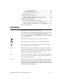
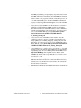
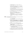
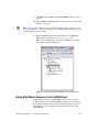
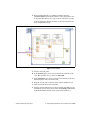
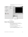
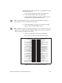
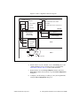
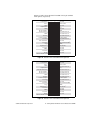
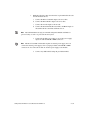
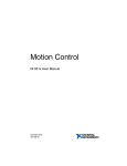
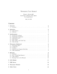
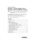
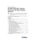
Getting Started with NI 951x
C Series Modules and LabVIEW
™
If you are a new user of the National Instruments LabVIEW software or are
unfamiliar with LabVIEW, refer to the Getting Started with LabVIEW manual for
information about LabVIEW and LabVIEW terminology.
Note
This tutorial demonstrates how to develop a motion application using the
NI 951x C Series modules in LabVIEW using the RIO Scan Interface and
the LabVIEW NI SoftMotion Module. The application uses a CompactRIO
Reconfigurable Embedded system with LabVIEW and the LabVIEW
NI SoftMotion Module to perform a series of two-axis moves. While
developing this application, you will learn the concepts and techniques
necessary to develop deterministic motion applications using
NI SoftMotion function blocks and the RIO Scan Interface. The RIO Scan
Interface enables you to use C Series modules directly from LabVIEW
Real-Time.
Contents
Conventions ............................................................................................ 2
Required Components............................................................................. 3
Required Software ........................................................................... 3
Required Hardware .......................................................................... 3
Related Documentation.................................................................... 4
NI SoftMotion Module Overview........................................................... 6
NI SoftMotion Module Tutorial.............................................................. 7
Setting Up the Hardware.................................................................. 7
Installing Software on and Configuring the Controller ................... 7
Creating a Project in Scan Interface Mode ...................................... 9
Adding NI SoftMotion Resources to the LabVIEW Project ........... 10
Adding Axes to the Project....................................................... 11
Adding Coordinates to the Project............................................ 12
Configuring Axes for Stepper Drive Interface Modules ................. 13
Using the Interactive Test Panel ...................................................... 15
Creating a VI in Scan Interface Mode ............................................. 16
Configuring the Timed Loop.....................................................16
Creating a Move Profile ............................................................17
Deploying, Testing, and Using the VI..............................................20
What You Have Learned ..................................................................21
Connecting the NI 9512 to Hardware......................................................22
Connecting to Drives Using the 37-Pin Terminal Block..................23
Configuring and Connecting Servo Axes ................................................26
Setting Up a Distributed System .............................................................31
Setting Up a System With An NI 9144 Chassis ...............................31
Software Installation and Configuration With the NI 9144 .............32
Adding the EtherCAT Master Device To the LabVIEW Project.....35
Where to Go for Support .........................................................................36
Conventions
The following conventions appear in this manual:
»
The » symbol leads you through nested menu items and dialog box options
to a final action. The sequence Options»Settings»General directs you to
pull down the Options menu, select the Settings item, and select General
from the last dialog box.
This icon denotes a tip, which alerts you to advisory information.
This icon denotes a note, which alerts you to important information.
This icon denotes a caution, which advises you of precautions to take to
avoid injury, data loss, or a system crash.
bold
Bold text denotes items that you must select or click in the software, such
as menu items and dialog box options. Bold text also denotes parameter
names, controls and indicators on the front panel, dialog boxes, sections
of dialog boxes, menu names, and palette names.
italic
Italic text denotes variables, emphasis, a cross-reference, or an introduction
to a key concept. Italic text also denotes text that is a placeholder for a word
or value that you must supply.
monospace
Monospace text denotes text or characters that you should enter from the
keyboard, sections of code, programming examples, and syntax examples.
This font is also used for the proper names of disk drives, paths, directories,
programs, subprograms, subroutines, device names, functions, operations,
variables, filenames, and extensions.
Getting Started with NI 951x C Series Modules and LabVIEW
2
ni.com
Required Components
This section lists the software and hardware used in the NI SoftMotion
Module Tutorial section of this document. This section also lists documents
you may find helpful while completing the tutorial.
Required Software
The following software is required for this tutorial:
❑ LabVIEW 2009 or later
❑ LabVIEW 2009 Real-Time Module or later
❑ NI-RIO 3.2.0 or later
❑ LabVIEW 2009 NI SoftMotion Module or later
Required Hardware
The following hardware is required for this tutorial:
❑ CompactRIO controller and chassis that support the RIO Scan
Interface
or
❑ NI 9144 distributed chassis and compatible real-time controller. Refer
to the Setting Up a Distributed System section of this document for
information about setting up and configuring the NI 9144 distributed
chassis for use with the NI 951x modules.
❑ Two NI 9512 single-axis stepper drive interface modules
❑ Power supply for the controller
❑ A separate power supply for the modules
Note Refer to the hardware specifications for information about selecting an appropriate
power supply.
❑ Ethernet connection and cable
Tip Even if you do not have the specified hardware, you can follow the steps in the
NI SoftMotion Module Tutorial section of this document and perform offline configuration
to learn concepts about using the NI SoftMotion Module with LabVIEW. Refer to the
Configuring a Project for a CompactRIO Reconfigurable or Integrated System (Scan
Interface) topic of the LabVIEW Help for information about offline configuration.
© National Instruments Corporation
3
Getting Started with NI 951x C Series Modules and LabVIEW
Alternatively, you can create an NI SoftMotion simulated axis. With a simulated axis you
can create and execute motion applications without any hardware installed. Refer to the
Working with Simulated Axes topic of the NI SoftMotion Module Help for more
information about simulated axes.
Related Documentation
The following documents contain information that you may find helpful as
you read this tutorial:
•
Operating instructions for the controller and modules (shipped with the
hardware and available at ni.com/manuals).
•
NI 951x User Manual—Use this document to learn additional
information about the electrical and mechanical aspects of the NI 951x
C Series drive interface modules.
•
LabVIEW NI SoftMotion Module Help—Use this help file to learn
about using NI SoftMotion in LabVIEW including information about
function blocks and using the NI SoftMotion Module with the
LabVIEW Project. To access this help file from LabVIEW, select
Help»LabVIEW Help, then expand the LabVIEW NI SoftMotion
Module book on the Contents tab.
•
Getting Started with NI 9512 C Series Drive Interface Modules and
P7000 Series Stepper Drives—Use this document as a tutorial to learn
how use NI 9512 modules with the P7000 series stepper drives and
stepper motors available from NI. Access this document by selecting
Start»All Programs»National Instruments»LabVIEW»
LabVIEW Manuals»Getting_Started_NI_9512_P7000.pdf.
•
Getting Started with NI 9512 C Series Drive Interface Modules and
AKD Analog Servo Drives—Use this document to learn how use
NI 9512 modules with the AKD analog servo drives and AKM servo
motors available from NI. Access this document by selecting Start»All
Programs»National Instruments»LabVIEW»LabVIEW Manuals»
Getting_Started_NI_9512_AKD.pdf.
•
Getting Started with NI 9514/16 C Series Drive Interface Modules and
AKD Analog Servo Drives—Use this document to learn how use
NI 9514 and NI 9516 modules with the AKD analog servo drives and
AKM servo motors available from NI. Access this document by
selecting Start»All Programs»National Instruments»LabVIEW»
LabVIEW Manuals»Getting_Started_NI_9514_NI_9516_AKD.pdf.
Getting Started with NI 951x C Series Modules and LabVIEW
4
ni.com
•
LabVIEW Help—Use the LabVIEW Help to access information about
LabVIEW programming concepts, step-by-step instructions for using
LabVIEW, and reference information about LabVIEW VIs, functions,
palettes, menus, tools, properties, methods, events, dialog boxes, and
so on. The LabVIEW Help also lists the LabVIEW documentation
resources available from National Instruments. Access the LabVIEW
Help by selecting Help»LabVIEW Help.
•
Getting Started with LabVIEW—Use this document as a tutorial to
familiarize yourself with the LabVIEW graphical programming
environment and the basic LabVIEW features you use to build data
acquisition and instrument control applications. Access the Getting
Started with LabVIEW PDF by selecting Start»All Programs»
National Instruments»LabVIEW»LabVIEW Manuals»
LV_Getting_Started.pdf.
•
Getting Started with the LabVIEW Real-Time Module—Use this
document to learn how to develop a real-time project and VIs, from
setting up RT targets to building, debugging, and deploying real-time
applications. Access the Getting Started with the LabVIEW Real-Time
Module PDF by selecting Start»All Programs»National Instruments»
LabVIEW»LabVIEW Manuals»RT_Getting_Started.pdf.
•
CompactRIO Reference and Procedures (Scan Interface)—Use this
help file to learn about using the CompactRIO system in Scan Interface
programming mode. To access this help file from LabVIEW, select
Help»LabVIEW Help, then expand Real-Time Module on the
Contents tab and select the CompactRIO Reference and Procedures
(Scan Interface) book.
•
NI 9144 User Guide and Specifications—Use this document to learn
additional information about how to connect the NI 9144 chassis to a
network, how to use the NI 9144 chassis features, and contains the
NI 9144 chassis specifications.
•
NI Industrial Communications for EtherCAT software documentation
© National Instruments Corporation
5
Getting Started with NI 951x C Series Modules and LabVIEW
NI SoftMotion Module Overview
The LabVIEW NI SoftMotion Module allows you to create deterministic
motion control applications using the LabVIEW Real-Time Module and
the RIO Scan Interface.
This document covers using the NI 951x C Series modules with the RIO Scan
Interface. For information about using the NI 951x modules with LabVIEW FPGA,
refer to the Motion Modules book of the LabVIEW Help.
Note
The following figure shows the NI SoftMotion architecture when you use
the NI SoftMotion Module with NI 951x C Series drive interface modules
and the RIO Scan Interface.
Windows
Host HMI and
Axis Settings:
LabVIEW Project
LabVIEW Real-Time Processor
(CompactRIO Controller, Real-Time PXI)
User VI
NI SoftMotion
APIs
CompactRIO with NI Scan Engine
NI SoftMotion
NI 951x cRIO Axis
Communication
Module
Motion Manager
User VI
NI SoftMotion
APIs
RIO Hardware
Supervisory
Control
cRIO
Chassis
NI 951x
C Series
Module(s)
EtherCAT with NI Scan Engine
Trajectory
Generator
NI 951x EtherCAT Axis
Communication
Module
EtherCAT
C Series
Chassis
NI 951x
C Series
Module(s)
Figure 1. NI SoftMotion and NI 951x Module Architecture
You use the LabVIEW Project to configure all of your axis settings, test
your configuration, and tune your servo motors. When your hardware
configuration is complete, you use NI SoftMotion to create move profiles.
The tutorial uses the NI SoftMotion function block API to create a VI.
NI SoftMotion function blocks contain status inputs and outputs used to
monitor and maintain the state of each individual function block. The
function block API is a non-blocking, or asynchronous, API you use
to communicate with your motion hardware. Refer to the NI SoftMotion
Help book of the LabVIEW Help for more information about function block
programming and other NI SoftMotion APIs.
Getting Started with NI 951x C Series Modules and LabVIEW
6
ni.com
NI SoftMotion Module Tutorial
This section contains a tutorial that uses the NI SoftMotion function blocks
to perform a two axis move. You use two NI 9512 stepper drive interface
modules in open-loop mode, so you are not required to make any additional
feedback device or other hardware connections.
The settings configured in this tutorial may not be appropriate for your actual motion
system. Hardware connections are minimized for demonstration purposes. Refer to the
Connecting the NI 9512 to Hardware section and the Configuring and Connecting Servo
Axes section for more information about drive and I/O connections.
Note
Setting Up the Hardware
Complete the following steps to set up the hardware for the application in
this tutorial.
This tutorial covers setting up NI 951x modules in a CompactRIO controller. If you
are using an NI 9144 distributed chassis, refer to the Setting Up a Distributed System
section for setup instructions.
Note
Note
1.
Install the real-time CompactRIO controller on the FPGA backplane if
you are not using an integrated controller and backplane. Refer to the
controller operating instructions for information about installing the
controller.
2.
Install the NI 9512 modules in slot 1 and slot 2 of the chassis.
3.
Connect the controller to a power supply and an Ethernet network on
the same subnet as the development computer. Refer to the controller
operating instructions for information about wiring the controller to
the power supply and Ethernet network.
4.
Connect the modules to a power supply. Refer to the module operating
instructions for information about selecting an appropriate power
supply.
5.
Connect the module to a drive and other I/O, if available. Refer to
Figure 11 for a simplified connection diagram.
You cannot complete this tutorial if the module power supply is not connected.
Installing Software on and Configuring the Controller
Complete the following steps to configure the controller and install
software on it. If you are setting up a distributed system using the NI 9144
distributed chassis, refer to the Software Installation and Configuration
With the NI 9144 section for software installation instructions.
© National Instruments Corporation
7
Getting Started with NI 951x C Series Modules and LabVIEW
1.
Launch Measurement & Automation Explorer (MAX) on the
development computer.
2.
Select the controller under Remote Systems in the Configuration
pane. If you do not see the controller, you may need to disable the
firewall on the development computer.
3.
Verify that the Serial Number in the Identification section matches
the serial number on the device.
4.
If you do not want to format the disk on the controller, eliminating all
installed software and files, power on the controller and skip to step 12.
5.
Set the Safe Mode switch on the controller to the On position.
6.
Power on the controller. If it is already powered on, press the Reset
button on the controller to reboot it.
7.
Right-click the controller under Remote Systems in the
Configuration pane and select Format Disk. Click Yes on the
dialog box that appears.
8.
When MAX finishes formatting the disk, set the Safe Mode switch
to the Off position and press the Reset button on the controller to
reboot it.
The following instructions apply to MAX 4.7 or later. Earlier versions of MAX may
have slightly different settings names and locations.
Note
9.
Select the System Settings tab and type a descriptive name for the
system in the Name field.
10. (Optional) Complete this step only if the target has an empty IP address
(0.0.0.0). Select the Network Settings tab and select DHCP or Link
Local from the Configure IPv4 Address list to assign an IP address
or select the Static to specify a static IP address in the IPv4 Address
section.
11. Click Save on the toolbar and let MAX reboot the system.
12. When the new system name appears under Remote Systems, expand
the controller item in the tree, right-click Software, and select
Add/Remove Software.
13. Select a recommended software set that includes NI-RIO 3.2.0 or later
with NI Scan Engine Support and the following add-ons enabled:
•
LabVIEW NI SoftMotion Module
•
NI Scan Engine Support for LabVIEW NI SoftMotion Module
14. Click Next to install the selected software on the controller. Click Help
if you need information about installing recommended software sets.
15. After MAX finishes installing software on the controller, close MAX.
Getting Started with NI 951x C Series Modules and LabVIEW
8
ni.com
Creating a Project in Scan Interface Mode
Scan Interface mode enables you to use C Series modules directly from
LabVIEW Real-Time. Modules that you use in Scan Interface mode appear
directly under the chassis item in the Project Explorer window. Unlike
most C Series modules, NI 951x modules are not directly configurable
from the Project Explorer window and no I/O variables are directly
available under the module.
Refer to the Select Programming Mode Dialog Box topic of the CompactRIO
Reference and Procedures (Scan Interface) book of the LabVIEW Help for more
information about Scan Interface mode.
Tip
Use a LabVIEW project to manage VIs, targets, and I/O modules on the
development computer. Complete the following steps to create a LabVIEW
project:
1.
Launch LabVIEW.
2.
Click the Empty Project link in the Getting Started window to
display the Project Explorer window. You can also select File»New
Project to display the Project Explorer window.
3.
Select Help and make sure that Show Context Help is checked. You
can refer to the context help throughout the tutorial for information
about items on the block diagram.
4.
Right-click the top-level project item in the Project Explorer window
and select New»Targets and Devices from the shortcut menu to
display the Add Targets and Devices dialog box.
5.
Make sure that the Existing target or device radio button is selected.
Tip If you do not have hardware installed, you can select the New target or device radio
button to display a list of targets and devices that you can create without a physical target
or device present. Throughout this tutorial, you can perform similar offline configuration
steps to follow along and learn about using the NI SoftMotion Module and LabVIEW.
6.
Expand Real-Time CompactRIO.
7.
Select the CompactRIO controller to add to the project and click OK.
8.
If you have LabVIEW FPGA installed, the Select Programming
Mode dialog box appears. Select Scan Interface to put the system into
Scan Interface mode.
Use the CompactRIO Chassis Properties dialog box to change the programming
mode in an existing project. Right-click the CompactRIO chassis in the Project Explorer
window and select Properties from the shortcut menu to display this dialog box.
Tip
© National Instruments Corporation
9
Getting Started with NI 951x C Series Modules and LabVIEW
9.
Click Discover in the Discover C Series Modules? dialog box if it
appears.
10. Click Continue. LabVIEW adds the controller, the chassis, and all the
modules to the project.
Note If you are using an NI 9144 chassis, refer to the Adding the EtherCAT Master Device
To the LabVIEW Project section for instructions about adding the EtherCAT master device
and detecting the C Series modules.
11. When LabVIEW finishes discovering hardware, select File»Save
Project and save the project as 951x_Tutorial.lvproj.
When you have finished these steps your LabVIEW project should
look similar to the image in Figure 2.
Figure 2. Project Explorer Window with Modules in Scan Interface Mode
Adding NI SoftMotion Resources to the LabVIEW Project
In this section you will create NI SoftMotion I/O resources tied to the
C Series modules. You use the NI SoftMotion I/O resources in your VIs
instead of I/O variables. Refer to the NI SoftMotion Module book of the
LabVIEW Help for more information about motion I/O resources and
NI SoftMotion.
Getting Started with NI 951x C Series Modules and LabVIEW 10
ni.com
Adding Axes to the Project
NI SoftMotion axes are tied to a specific C Series module in the project, and
allow configuration of the I/O present on the module. To configure and use
the NI 951x modules in Scan Interface mode you must add axes to the
RT target and use the motion I/O resource associated with that axis in your
VIs. Complete the following steps to add an NI SoftMotion axis to the
project:
1.
Right-click the target in the Project Explorer window and select
New»NI SoftMotion Axis from the shortcut menu to open the Axis
Manager dialog box, shown in Figure 3.
2.
Click Add New Axis twice so that both NI 9512 modules are
associated with NI SoftMotion axes. Axes are automatically bound to
an available module. You can double-click the axis name to rename the
axis and give it a descriptive name, but you cannot use the same name
for two different axes.
Figure 3. Axis Manager Dialog Box
Tip Click Change Binding to open the Resource Binding dialog box and change the
hardware the axis is associated with, if necessary.
3.
Note
Click OK to close the Axis Manager dialog box. All axes are added
to the Project Explorer window.
You cannot associate more than one axis with the same C Series module.
© National Instruments Corporation
11 Getting Started with NI 951x C Series Modules and LabVIEW
Adding Coordinates to the Project
NI SoftMotion axes can be grouped into coordinate spaces. Coordinate
spaces are logical, multidimensional groups of axes. Like axes, coordinate
spaces have associated I/O resources that you use as resource inputs in your
VIs. Complete the following steps to add a coordinate space to the project:
1.
Right-click the target in the Project Explorer window and select
New»NI SoftMotion Coordinate Space from the shortcut menu to
open the Configure Coordinate Space dialog box, shown in Figure 4.
2.
Move Axis 1 and Axis 2 from the Available Axes column to the
Coordinate Axes column using the arrow. Double-click the
coordinate space name to rename the coordinate space and give it a
descriptive name.
Figure 4. Configure Coordinate Space Dialog Box
Note When using coordinate resources, target positions and other coordinate information
are provided in a one-dimensional array with axis information provided in the order that
axes are added using this dialog box. Refer to the NI SoftMotion Module book of the
LabVIEW Help for more information.
3.
Click OK to close the Configure Coordinate Space dialog box.
Getting Started with NI 951x C Series Modules and LabVIEW 12
ni.com
Your project now contains the axes and coordinate spaces you will use in
the application. Your LabVIEW project should look similar to Figure 5.
Figure 5. Completed Project with Motion Resources
Configuring Axes for Stepper Drive Interface Modules
In this section you will configure the axes associated with your NI 9512
C Series modules using the Axis Configuration dialog box.
Refer to the Configuring and Connecting Servo Axes section of this document for
information about configuring servo modules.
Tip
© National Instruments Corporation
13 Getting Started with NI 951x C Series Modules and LabVIEW
The Axis Configuration dialog box includes configuration options for
stepper drive command signals, feedback devices, motion and digital I/O,
trajectory, and axis setup. Figure 6 shows the parts of the Axis
Configuration dialog box for NI 9512 C Series modules.
Figure 6. Axis Configuration Dialog Box for NI 9512 Modules
Note Refer to the NI SoftMotion Module book of the LabVIEW Help for detailed
information about each configuration option.
Complete the following steps to configure the axes. If you are configuring
axes for a p-command drive, refer to Appendix B, Position Command
Connections, in the NI 951x User Manual section of this document.
1.
Right-click the axis in the Project Explorer window and select
Properties from the shortcut menu to open the Axis Configuration
dialog box.
2.
On the General Settings page, confirm that Loop Mode is set to
Open-Loop. Axes configured in open-loop mode produce step outputs
but do not require feedback from the motor to verify position.
3.
Also on the General Settings page, confirm that the Axis Enabled and
Enable Drive on Transition to Active Mode checkboxes contain
checkmarks. These selections configure the axes to automatically
activate when the NI Scan Engine switches to Active mode.
Disable these options to prevent axes from automatically activating when the
NI Scan Engine switches to Active mode.
Note
Getting Started with NI 951x C Series Modules and LabVIEW 14
ni.com
4.
If the modules do not have physical limit and home input connections,
you must disable these input signals for proper system operation. To
disable limits and home, go to the Limits & Home page and remove
the checkmarks from the Enable checkboxes in the Forward Limit,
Reverse Limit, and Home Switch sections.
5.
Configure any additional I/O settings according to your system
requirements.
6.
Click OK to close the Axis Configuration dialog box.
7.
Repeat steps 1 through 6 for Axis 2.
Caution Make sure all hardware connections are made and power is turned on before
deploying the project. Deployment switches the NI Scan Engine to Active mode and
enables your axes and drive, if connected, so that you can start a move immediately. Refer
to the Deploying and Running VIs on an RT Target topic of the LabVIEW Help for more
information about deployment and for troubleshooting tips.
8.
Right-click the controller item in the Project Explorer window and
select Deploy All from the shortcut menu to deploy the axes,
coordinate, and axis settings to the RT target.
Using the Interactive Test Panel
Use the Interactive Test Panel to test and debug your motion system and
configuration settings on the selected axis. With the Interactive Test Panel
you can perform a simple straight-line move and monitor move and I/O
status information, change move constraints, get information about errors
and faults in the system, and view position or velocity plots of the move. If
you have a feedback device connected to your system, you can also obtain
feedback position and position error information.
Complete the following steps to test your setup after configuring your axes
using the Axis Configuration dialog box:
1.
Right-click the axis in the Project Explorer window and select
Interactive Test Panel from the shortcut menu.
2.
Set the desired position, move mode, and move constraints using the
tabs. Refer to the NI SoftMotion Module book of the LabVIEW Help
for detailed information about the items available in this dialog box.
3.
Click the Start button on the bottom of the dialog box to start the move
with the configured options.
4.
Use the Status and Plots tabs to monitor the move while it is in
progress.
© National Instruments Corporation
15 Getting Started with NI 951x C Series Modules and LabVIEW
Creating a VI in Scan Interface Mode
In this section you will create a VI that uses the NI SoftMotion axis and
coordinate space I/O resources you created earlier. Refer to the Real-Time
Module book of the LabVIEW Help for more information about Scan
Interface mode and the NI Scan Engine.
Configuring the Timed Loop
A Timed Loop synchronized to the NI Scan Engine enables your
time-sensitive motion function blocks to execute at the scan rate. Any code
placed inside a Timed Loop is guaranteed to execute once per scan period,
or at an interval you specify. Memory allocation should be minimized in
Timed Loops to avoid introducing jitter into the system.
If your application does not need to run at the scan rate, you can use a While Loop
with a Wait Until Next ms Multiple function to control the loop rate.
Tip
Complete the following steps to configure the Timed Loop:
1.
Right-click the controller item in the Project Explorer window and
select New»VI from the shortcut menu to open a blank VI.
2.
Place a Timed Loop on the block diagram of the VI.
3.
Double-click the Input Node of the Timed Loop to open the
Configure Timed Loop dialog box.
4.
Under Loop Timing Source, for Source Type, select Synchronize to
Scan Engine. You can click the Help button for information about
synchronizing to the NI Scan Engine.
5.
Under Loop Timing Attributes, set the Period to 5 scans. This step
is optional but allows the Timed Loop to execute synchronized to the
NI Scan Engine but at a slower rate.
Getting Started with NI 951x C Series Modules and LabVIEW 16
ni.com
The Configure Timed Loop dialog box should look similar to the
following figure.
Figure 7. Configuring the Timed Loop
6.
Click OK.
Creating a Move Profile
This example uses the NI SoftMotion Line and Read function blocks to
create a simple move profile and monitor the position during the move.
The NI SoftMotion palette is not visible by default. Refer to the Showing and Hiding
Palette Categories topic in the LabVIEW Help for information about editing the palette
view to make the NI SoftMotion function blocks more accessible.Complete the following
steps to set up the move:
Tip
1.
Place a Line function block inside the Timed Loop. The NI SoftMotion
function blocks are located on the NI SoftMotion»Advanced palette.
2.
Drag the Coordinate Space 1 resource from the LabVIEW Project on
to the block diagram outside the Timed Loop and wire it to the
resource input on the function block.
3.
Right-click the execute input and select Create»Control from the
shortcut menu to add a control to the front panel for this input.
4.
Repeat step 3 for the position, velocity, and acceleration inputs to add
controls to the front panel for each of these inputs.
© National Instruments Corporation
17 Getting Started with NI 951x C Series Modules and LabVIEW
5.
Place a second Line function block inside the Timed Loop.
6.
Wire the error terminals and resource terminals of the Line function
blocks together.
7.
Wire the done output of the first Line function block to the execute
input of the second Line function block.
8.
Wire the velocity and acceleration inputs of the second Line function
block to the controls created in step 3. This configures the second
function block to use the same move constraint values as the first
function block.
9.
Right-click the position input and select Create»Control from the
shortcut menu to add a control for the second position to the front
panel.
10. Add a Read function block to the block diagram and connect the
resource input to the Coordinate Space 1 resource.
Reading the position and plotting is generally executed on the host by reading data
published by the target and not in the deterministic Timed Loop. Reading is included in this
example for simplicity.
Note
11. Add a Merge Errors function to the block diagram and wire the error
out outputs of the Read function block and second Line function block
to the Merge Errors function.
12. Right-click the error out output of the Merge Errors function and
select Create»Indicator from the shortcut menu to add an indicator to
the front panel.
13. Wire the error out output to the edge of the Timed Loop.
14. Right-click the loop tunnel created for the error out output and select
Replace with Shift Register from the shortcut menu. This transfers
the error information to the next loop iteration.
15. Wire the error in inputs of the Line and Read function blocks to the
shift register created on the other side of the Timed Loop.
16. Right-click the shift register and select Create»Constant from the
shortcut menu to initialize the error cluster outside the Timed Loop.
Because the hardware uses the LabVIEW Real-Time module, all
function block arrays and clusters are initialized outside the Timed
Loop to prevent jitter in the system.
17. Create a constant for the position[] input on the Read function block
and enter 0 for the first two elements of the array. Move the position[]
constant outside the Timed Loop. This initializes the array so that the
function block does not need to allocate any memory.
Getting Started with NI 951x C Series Modules and LabVIEW 18
ni.com
18. Right-click the Timed Loop conditional terminal and select
Create»Control from the shortcut menu to add a Stop button to the
front panel. This allows you to stop execution of the VI at any time.
Your block diagram should look similar to the following when you
have completed these steps:
Figure 8. Block Diagram
19. Switch to the front panel.
20. In the position[] array, enter 5000 for the first two elements of the
array. This specifies an x, y position of 5000, 5000.
21. In the position[] 2 array, enter 0 for the first two elements of the array.
This moves the x and y axis back to 0, 0.
22. Keep the velocity and acceleration values at their defaults for now.
23. Add a waveform chart to the front panel.
24. Switch to the block diagram, move the waveform chart indicator into
the Timed loop if necessary, then connect the position[] out terminal
from the Read function block to the waveform chart indicator.
© National Instruments Corporation
19 Getting Started with NI 951x C Series Modules and LabVIEW
Your front panel should look similar to the following when you have
completed these steps:
Figure 9. Front Panel
25. Save the VI.
26. Save the project.
Deploying, Testing, and Using the VI
Complete the following steps to deploy, test, and use the VI:
1.
Run the VI. LabVIEW deploys the VI, and all modules and I/O
variables the VI uses, to the controller.
2.
Pulse the execute control to start execution.
3.
On the front panel, verify that the position graph updates.
4.
Stop the VI by clicking the Stop button.
5.
Change any of the input parameters, run the VI, and pulse execute
again to see how the different parameters interact.
Getting Started with NI 951x C Series Modules and LabVIEW 20
ni.com
What You Have Learned
This tutorial taught the following concepts about developing motion
applications using the NI SoftMotion Module and NI 951x C Series
modules.
•
NI 951x modules differ from most C Series modules in that they are
not directly configurable from the Project Explorer window when
you are using Scan Interface mode, and no I/O variables are directly
available under the module.
•
You must use NI SoftMotion to add axes to the RT target and associate
them with NI 951x modules in order to configure and use them in Scan
Interface mode. You then use the motion I/O resources associated with
those axes in your VIs.
•
NI SoftMotion axes are configured using the Axis Configuration
dialog box.
•
NI SoftMotion function blocks allow you to create deterministic
motion control applications using the function block programming
paradigm.
•
NI SoftMotion function blocks provide status outputs for advanced
state monitoring.
© National Instruments Corporation
21 Getting Started with NI 951x C Series Modules and LabVIEW
Connecting the NI 9512 to Hardware
This section describes how to connect the NI 9512 stepper drive interface
module to third-party drives using the NI 951x Cable and Terminal Block
bundle.
National Instruments offers several options for connecting the NI 9512 to
stepper or position command servo drives. Refer to Table 1 for available
NI 9512 connection options.
Table 1. NI 9512 Connection Options
Drive
P7000 Series Stepper
Connection Option
NI 9512 to P7000 Stepper Drive Connectivity Bundle
(NI part number 780552-01)
Note: Refer to Getting Started with NI 9512 C Series Drive Interface
Modules and P7000 Series Stepper Drives, available by selecting
Start»All Programs»National Instruments»LabVIEW»
LabVIEW Manuals»Getting_Started_NI_9512_P7000.pdf and on
ni.com/manuals, for information about connecting and using the
NI 9512 module with P7000 series stepper drives and stepper motors
available from NI.
AKD Analog Servo
NI 9512 to AKD Drive Cable
(NI part number 781525-01)
Note: Refer to Getting Started with NI 9512 C Series Drive Interface
Modules and AKD Analog Servo Drives, available by selecting
Start»All Programs»National Instruments»LabVIEW»
LabVIEW Manuals»Getting_Started_NI_9512_AKD.pdf and on
ni.com/manuals, for information about connecting and using the
NI 9512 module with AKD analog servo drives and AKM brushless
servo motors available from NI.
Mitsubishi MR-J2 or
MR-J3
NI 9930M Motion Control Accessory
(NI part number 781824-01)
Note: Refer to NI 9930 Motion Control Accessories User Guide,
available by selecting Start»All Programs»National Instruments»
LabVIEW»LabVIEW Manuals»
NI_9930_Motion_Control_Accessories_User_Guide.pdf and on
ni.com/manuals, for information about connecting and using the
NI 9512 module with the referenced Mitsubishi, Panasonic, and
Yaskawa servo drives.
Getting Started with NI 951x C Series Modules and LabVIEW 22
ni.com
Table 1. NI 9512 Connection Options (Continued)
Drive
Connection Option
Panasonic Minas-A or
Minas-A5
NI 9930P Motion Control Accessory
(NI part number 781823-01)
Note: Refer to NI 9930 Motion Control Accessories User Guide,
available by selecting Start»All Programs»National Instruments»
LabVIEW»LabVIEW Manuals»
NI_9930_Accessories_User_Guide.pdf and on ni.com/manuals, for
information about connecting and using the NI 9512 module with the
referenced Mitsubishi, Panasonic, and Yaskawa servo drives.
Yaskawa Sigma-II or
Sigma-V
NI 9930Y Motion Control Accessory
(NI part number 781822-01)
Note: Refer to NI 9930 Motion Control Accessories User Guide,
available by selecting Start»All Programs»National Instruments»
LabVIEW»LabVIEW Manuals»
NI_9930_Accessories_User_Guide.pdf and on ni.com/manuals, for
information about connecting and using the NI 9512 module with the
referenced Mitsubishi, Panasonic, and Yaskawa servo drives.
Other third-party
stepper or p-command
servo drive
NI 951x cable and terminal block bundle
(NI part number 780553-01)
Note: Refer to Appendix B, Position Command Connections, in the
NI 951x User Manual available by selecting Start»All Programs»
National Instruments»NI-RIO»CompactRIO»CompactRIO
Manuals»NI_951x_User_Manual.pdf and on ni.com/manuals, for
information about connecting and using the NI 9512 module with other
p-command servo drives.
Connecting to Drives Using the 37-Pin Terminal Block
Refer to the NI 951x User Manual for 37-pin terminal block pinouts for each
module.
Note
Complete the following steps to connect an NI 9512 drive interface module
to drives and other I/O:
1.
Install the module in the chassis as specified in the chassis
documentation.
Refer to the NI SoftMotion Module book of the LabVIEW Help for information about
chassis, slot, or software restrictions.
Note
2.
© National Instruments Corporation
Connect the module to the 37-pin terminal block using the NI 951x
37-pin terminal block cable.
23 Getting Started with NI 951x C Series Modules and LabVIEW
3.
Make the following connections from the 37-pin terminal block to the
external hardware device:
a.
Connect the Step and Direction outputs to the stepper drive.
b.
Connect the Drive Enable output to the stepper drive.
c.
Connect the Forward Limit, Reverse Limit, and Home inputs on
the terminal block to the limit and home sensors.
National Instruments strongly recommends using Drive Enable and limits for
personal safety, as well as to protect the motion system.
Note
d.
Connect the module power supply to one of the power supply
inputs on either the DSUB or MDR connector.
The NI 9512 requires an external power supply. You can connect the external power
supply to the Vsup input provided on the DSUB or MDR connector. Do not connect more
than one external power supply to the module.
Note
e.
Connect any additional I/O using the provided terminals.
Figure 10 shows the NI 9512 37-pin terminal block pinout.
19
20
Reverse Limit
21
Reserved
22
Vsup
23
Reserved
24
COM
25
Encoder 0 Phase A+
26
Encoder 0 Phase A–
27
Encoder 0 Phase B+
28
Position Capture
29
Encoder 0 Phase B–
30
Reserved
31
Reserved
32
COM†
33
Drive Enable†
34
Digital Input 3†
35
Direction (CCW)–†
36
Digital Input 2†
37
Step (CW)–†
3
COM
Digital Output 1†
2
Home
1
Forward Limit
Digital Input 0
4
COM
5
6
Encoder 0 Index+
8
COM
7
Encoder 0 Index–
+5V OUT
9
Position Compare
10
Reserved
11
Reserved
12
Digital Output 0†
13
Vsup†
14
Digital Input 1†
15
†
16
†
17
Step (CW)+†
18 GND
Direction (CCW)+
COM
Shield
†
Indicates DSUB connector signals.
Figure 10. NI 9512 37-Pin Terminal Block Pin Assignments
Getting Started with NI 951x C Series Modules and LabVIEW 24
ni.com
Figure 11 shows a simplified connection diagram.
DSUB Connector
MDR Connector
Step±/CW
Encoder 0 Phase A, B, Index
Direction±/CCW
+5 V OUT
Drive Fault
Forward Limit, Reverse Limit, Home
Drive Enable
Vsup
NI 9512
Limit and Home
Sensors
NI Connection
Accessory/
Custom Cable
Power Supply
Step±/CW
Direction±/CCW
Drive
Drive Fault
Drive Enable
Motor
Stepper Motor
Encoder (optional)
Figure 11. NI 9512 Connection Diagram
4.
Install software on your controller, create a LabVIEW project, and
add NI SoftMotion axes by following the steps provided in the
NI SoftMotion Module Tutorial section of this document.
5.
Right-click the axis in the Project Explorer window and select
Properties from the shortcut menu to open the Axis Configuration
dialog box.
6.
Configure your I/O settings according to your system requirements
using the Axis Configuration dialog box.
© National Instruments Corporation
25 Getting Started with NI 951x C Series Modules and LabVIEW
Configuring and Connecting Servo Axes
This section provides additional information about configuring the NI 9514
and NI 9516 servo drive interface modules and connecting to drives and
other I/O using the NI 951x Cable and Terminal Block bundle.
Refer to Getting Started with NI 9514/16 C Series Drive Interface Modules
and AKD Analog Servo Drives, available by selecting Start»All Programs»
National Instruments»LabVIEW»LabVIEW Manuals»
Getting_Started_NI_9514_NI_9516_AKD.pdf and on ni.com/manuals, for information
about connecting and using the NI 9514 and NI 9516 module with AKD analog servo
drives and AKM brushless servo motors available from NI.
Note
Complete the following steps to connect an NI 9514 or NI 9516 drive
interface module to drives and other I/O:
1.
Install the module in the chassis as specified in the chassis
documentation.
Refer to the NI SoftMotion Module book of the LabVIEW Help for information about
chassis, slot, or software restrictions.
Note
2.
Connect the module to the 37-pin terminal block using the NI 951x
37-pin terminal block cable.
Getting Started with NI 951x C Series Modules and LabVIEW 26
ni.com
Figures 12 and 13 show the NI 9514 and NI 9516 37-pin terminal
block pinouts, respectively.
23
24
COM
25
Encoder 0 Phase A+
26
21
Vsup
Reserved
Encoder 0 Phase A–
COM
Encoder 0 Index+
8
COM
7
Encoder 0 Index–
6
22
20
Reserved
Digital Input 0
5
Reverse Limit
COM
4
Reserved
3
19
2
Home
1
Forward Limit
9
27
Encoder 0 Phase B+
Position Compare
10
28
Position Capture
Reserved
11
29
Encoder 0 Phase B–
Drive Command†
Reserved
12
30
Reserved
31
Drive Command COM†
Vsup†
14
32
COM†
Digital Input 1†
15
33
Drive Enable†
Reserved
16
34
Reserved
COM†
17
35
Reserved
Reserved
18 GND
36
Reserved
37
Reserved
13
+5V OUT
Shield
†
Indicates DSUB connector signals.
Figure 12. NI 9514 37-Pin Terminal Block Pin Assignments
Encoder 1 Phase A–
24
Encoder 1 Phase B+
25
Encoder 0 Phase A+
26
Encoder 0 Phase A–
Encoder 1 Phase B–
8
COM
7
Encoder 0 Index–
6
Encoder 0 Index+
5
Vsup
23
21
Encoder 1 Phase A+
Digital Input 0
22
20
Reverse Limit
COM
4
Reserved
3
19
2
Home
1
Forward Limit
+5V OUT
9
27
Encoder 0 Phase B+
Position Compare
10
28
Position Capture
Reserved
11
29
Encoder 0 Phase B–
Drive Command†
12
30
Reserved
Reserved
13
31
Drive Command COM†
†
14
32
COM†
†
15
33
Drive Enable†
Reserved
16
34
Reserved
COM†
17
35
Reserved
Reserved
18 GND
36
Reserved
37
Reserved
Vsup
Digital Input 1
Shield
†
Indicates DSUB connector signals.
Figure 13. NI 9516 37-Pin Terminal Block Pin Assignments
© National Instruments Corporation
27 Getting Started with NI 951x C Series Modules and LabVIEW
3.
Make the following connections from the 37-pin terminal block to the
external hardware device:
a.
Connect the Drive Command output to the servo drive.
b.
Connect the Drive Enable output to the servo drive.
c.
Connect the encoder inputs to the encoder.
d.
Connect the Forward Limit, Reverse Limit, and Home inputs on
the terminal block to the limit and home sensors.
National Instruments strongly recommends using Drive Enable and limits for
personal safety, as well as to protect the motion system.
Note
e.
Connect the module power supply to one of the power supply
inputs on either the DSUB or MDR connector.
The NI 9514 and NI 9516 modules require an external power supply. You can
connect the external power supply to the Vsup input provided on the DSUB or MDR
connector. Do not connect more than one external power supply to the module.
Note
f.
Connect any additional I/O using the provided terminals.
Getting Started with NI 951x C Series Modules and LabVIEW 28
ni.com
Figure 14 shows a simplified connection diagram.
DSUB Connector
MDR Connector
Drive Command
Encoder 0 Phase A, B, Index
Drive Enable
Encoder 1 Phase A, B
(NI 9516 Only)
Drive Fault
+5 V OUT
Vsup
Forward Limit, Reverse Limit, Home
NI 9514/9516
Limit and Home
Sensors
NI Connection
Accessory/
Custom Cable
Power Supply
Drive Command
Drive Enable
Drive
Drive Fault
Motor
Motor
Encoder 0
Encoder 1 (NI 9516 only)
Figure 14. NI 9514 and NI 9516 Connection Diagram
Note Refer to the NI 951x User Manual for connection diagrams specific to each NI 951x
module.
4.
Install software on your controller, create a LabVIEW project, and
add NI SoftMotion axes by following the steps provided in the
NI SoftMotion Module Tutorial section of this document.
5.
Right-click the axis in the Project Explorer window and select
Properties from the shortcut menu to open the Axis Configuration
dialog box.
Servo axes only operate in closed-loop mode, so a feedback device is
required. If you are using an NI 9514 or NI 9516 drive interface
module you must configure additional options for the feedback device,
servo control loop, and drive command output for the servo drive.
© National Instruments Corporation
29 Getting Started with NI 951x C Series Modules and LabVIEW
Figure 15 shows the parts of the Axis Configuration dialog box for
NI 9514 and NI 9516 C Series modules.
Figure 15. Axis Configuration Dialog Box for NI 9514 and NI 9516 Modules
6.
Configure your I/O settings according to your system requirements
using the Axis Configuration dialog box.
7.
Right-click the axis in the Project Explorer window and select Gain
Tuning Panel from the shortcut menu to access the Gain Tuning
Panel.
8.
Use the Gain Tuning Panel to tune the control loop settings and
determine the relative stability of the servo axis. Refer to the Using the
Gain Tuning Panel topic in the NI SoftMotion Module book of the
LabVIEW Help for detailed information about the Gain Tuning Panel
and servo system tuning instructions.
Getting Started with NI 951x C Series Modules and LabVIEW 30
ni.com
Setting Up a Distributed System
Setting Up a System With An NI 9144 Chassis
Complete the following steps to set up the EtherCAT master and configure
the distributed network for use with the NI 9144:
1.
Install the real-time controller into the CompactRIO or PXI system.
2.
Connect the controller to a power supply and an Ethernet network on
the same subnet as the development computer. Refer to the controller
operating instructions for information about wiring the controller to
the power supply and Ethernet network.
3.
Connect the secondary port of your EtherCAT Master directly to the
IN port (top port) on the NI 9144 chassis using a standard Category 5
Ethernet cable. If you are using the NI cRIO-9074 as your EtherCAT
Master, the secondary port is top port (LAN PORT #2). If you are using
a PXI system, you must add a PXI-8231/8232 network card for the
secondary port. You may expand the deterministic Ethernet network by
connecting an additional NI 9144 chassis or other slave devices to the
OUT port (bottom port) on the first NI 9144 chassis.
Host
Computer
Ethernet
Secondary
Primary
NI Master Controller
EtherCAT
IN
OUT
NI 9144 Expansion Chassis
Additional
NI 9144 Chassis/Slave Devices
Figure 16. Connecting the NI 9144 Chassis to Network
4.
Install the NI 9512 modules in slot 1 and slot 2 of the NI 9144 chassis.
The NI 9512 modules require high-speed interface slots. Some chassis may support
the high-speed interface in additional slots. Refer to ni.com for more information.
Note
5.
Connect the modules to a power supply. Refer to the module operating
instructions for information about selecting an appropriate power
supply.
© National Instruments Corporation
31 Getting Started with NI 951x C Series Modules and LabVIEW
Note
You cannot complete this tutorial if the module power supply is not connected.
6.
If using the NI 9144 chassis with a PXI master controller, disable
Legacy USB Support in the host PC BIOS, if it is enabled.
7.
Connect the module to a drive and other I/O, if available.
8.
Continue with the Software Installation and Configuration With the
NI 9144 section.
Software Installation and Configuration With the NI 9144
Complete the following steps to configure the controller and install
software on it:
1.
Launch Measurement & Automation Explorer (MAX) on the
development computer by clicking the MAX icon on the desktop,
or by selecting Start»All Programs»National Instruments»
Measurement & Automation.
2.
Select the controller under Remote Systems in the Configuration
pane. If you do not see the controller, you may need to disable the
firewall on the development computer.
3.
Verify that the Serial Number in the Identification section matches
the serial number on the device.
4.
If you do not want to format the disk on the controller, eliminating all
installed software and files, power on the controller and skip to step 12.
5.
Set the Safe Mode switch on the controller to the On position.
6.
Power on the controller. If it is already powered on, press the Reset
button on the controller to reboot it.
7.
Right-click the controller under Remote Systems in the
Configuration pane and select Format Disk. Click Yes on the dialog
box that appears.
8.
When MAX finishes formatting the disk, set the Safe Mode switch
to the Off position and press the Reset button on the controller to
reboot it.
9.
Select the System Settings tab and type a descriptive name for the
system in the Name field.
10. (Optional) Complete this step only if the target has an empty IP address
(0.0.0.0). Select the Network Settings tab and select DHCP or Link
Local from the Configure IPv4 Address list to assign an IP address
or select the Static to specify a static IP address in the IPv4 Address
section.
11. Click Save on the toolbar and let MAX reboot the system.
Getting Started with NI 951x C Series Modules and LabVIEW 32
ni.com
12. When the new system name appears under Remote Systems, expand
the controller item in the tree, right-click Software, and select
Add/Remove Software.
13. Select a recommended software set that includes NI-RIO 3.4.0 or later
with NI Scan Engine Support and the following add-ons enabled:
•
LabVIEW NI SoftMotion Module
•
NI Scan Engine Support for LabVIEW NI SoftMotion Module
•
IndCom for EtherCAT Scan Engine Support
14. Click Next to install the selected software on the controller. Click Help
if you need information about installing recommended software sets.
15. When MAX finishes installing the software on the controller, select the
controller under Remote Systems in the Configuration pane.
16. Click the Network Settings tab and expand More Settings in the eth1
section
17. Select EtherCAT from the Adapter Mode list.
Note These settings are not available if NI-Industrial Communications for EtherCAT is
not installed.
18. In the eth0 (Primary) section click More Settings and change Packet
Detection to Polling. Leave the Polling Interval at 1 ms.
© National Instruments Corporation
33 Getting Started with NI 951x C Series Modules and LabVIEW
When you have completed these steps the Network Settings tab will
look similar to Figure 17.
Figure 17. Network Settings Tab
19. Click Save.
20. Close MAX.
21. Continue with the Creating a Project in Scan Interface Mode section.
Getting Started with NI 951x C Series Modules and LabVIEW 34
ni.com
Adding the EtherCAT Master Device To the LabVIEW Project
If you are using the NI 9144 chassis, complete the following steps to add
the EtherCAT master device and detect the C Series modules:
1.
In the LabVIEW Project Explorer window, right-click the master
controller and select New»Targets and Devices.
2.
In the Add Targets and Devices dialog window shown in Figure 18,
select Existing target or device and expand the category EtherCAT
Master Device to auto-discover the EtherCAT port on the master
controller. An EtherCAT master device and modules can be added
manually at any time.
Figure 18. Adding the EtherCAT Master
When all the slave devices are discovered, the LabVIEW Project
Explorer window lists each slave device and any installed C Series
modules.
3.
© National Instruments Corporation
For more information about configuring the deterministic Ethernet
network, the NI 9144 chassis, and the C Series modules, refer to the
Related Documentation section of this document.
35 Getting Started with NI 951x C Series Modules and LabVIEW
Where to Go for Support
The National Instruments Web site is your complete resource for technical
support. At ni.com/support you have access to everything from
troubleshooting and application development self-help resources to email
and phone assistance from NI Application Engineers.
National Instruments corporate headquarters is located at
11500 North Mopac Expressway, Austin, Texas, 78759-3504.
National Instruments also has offices located around the world to help
address your support needs. For telephone support in the United States,
create your service request at ni.com/support and follow the calling
instructions or dial 512 795 8248. For telephone support outside the United
States, visit the Worldwide Offices section of ni.com/niglobal to access
the branch office Web sites, which provide up-to-date contact information,
support phone numbers, email addresses, and current events.
LabVIEW, National Instruments, NI, ni.com, the National Instruments corporate logo, and the Eagle
logo are trademarks of National Instruments Corporation. Refer to the Trademark Information at
ni.com/trademarks for other National Instruments trademarks. Other product and company
names mentioned herein are trademarks or trade names of their respective companies. For patents
covering National Instruments products/technology, refer to the appropriate location: Help»Patents
in your software, the patents.txt file on your media, or the National Instruments Patent Notice
at ni.com/patents. Refer to the Export Compliance Information at ni.com/legal/
export-compliance for the National Instruments global trade compliance policy and how to
obtain relevant HTS codes, ECCNs, and other import/export data.
© 2009–2011 National Instruments Corporation. All rights reserved.
372874D-01
Jul11