1
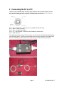
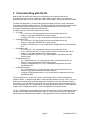
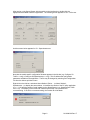
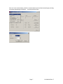
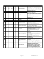
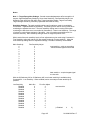
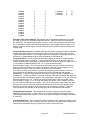
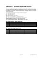
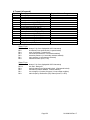
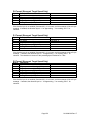
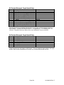
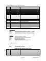
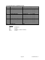
Stalker Speed Sensor User Manual
for Traffic, Stationary and Speedometer Models
1
2
3
4
Overview..............................................................................................................................1
Connecting the S3 to a PC ...................................................................................................3
Communicating with the S3 ..................................................................................................5
Configuring the S3................................................................................................................8
4.1
Reading the Current S3 Configuration.........................................................................8
4.2
Changing and Saving the Configuration ......................................................................9
4.3
Application Defaults..................................................................................................10
5 Operating the S3 ................................................................................................................11
5.1
Monitoring Speed Data .............................................................................................11
5.2
Logging Speed Data .................................................................................................11
5.3
Monitoring the AUX Pin.............................................................................................12
5.4
Controlling the S3 .....................................................................................................12
6 Advanced Configuration .....................................................................................................13
6.1
General Initialization File...........................................................................................13
6.2
Model Specific Configuration File..............................................................................13
6.3
Default Parameter Values.........................................................................................14
6.3.1
Application Defaults..............................................................................................14
6.3.2
Factory Defaults ...................................................................................................14
7 Advanced Operation...........................................................................................................15
Appendix A Command ID Table ...................................................................... A-1
Appendix B Streaming Speed Data Protocols.................................................. B-1
Appendix C Handshake Speed Data Protocols ................................................ C-1
Appendix D S3 Configuration Protocol............................................................. D-1
Appendix E Accessories.................................................................................. E-1
1 Overview
The Stalker Speed Sensor (S3) is available in four types: Traffic, Stationary, Speedometer and
Sports. This document covers the Traffic, Stationary and Speedometer types. Refer to
document 011-0081-00 Stalker Sports Speed Sensor User Manual for user information on the
Sports model.
The S3 Traffic is the most fully featured as it operates in moving or stationary mode and reports
patrol speed (ground speed), strong target speed, faster target speed and locked speed (target or
faster). The S3 Stationary operates in stationary mode only and reports strong and faster target
speeds. The S3 Speedometer operates in moving mode only and reports ground speed.
The S3 communicates over one of two serial communications port types: RS-232 or RS-485. An
RS-232 unit has separate single-ended transmit and receive signals and supports full-duplex
communication. An RS-485 unit uses a single differential pair of wires for both transmit and
receive and so provides only half-duplex communication, but it can communicate over longer
distances. The S3 Traffic is only available as an RS-232 model. The S3 Stationary and S3
Speedometer are available as RS-232 models or RS-485 models as different assembly options.
A common Configuration Protocol is used with all S3 Traffic, Stationary and Speedometer models
to query and make changes to the operational software parameters stored within the non-volatile
flash memory of the unit. A variety of Speed Data Protocol Formats are supported to convey
speed information from the S3.
This manual applies to:
• PC applications: Version 1.1.1.0 and later
Page 1
011-0080-00 Rev. E
•
•
•
•
•
S3 Traffic model operating code: Version 1.0.5 and later
S3 Stationary 232 model operating code: Version 1.0.9 and later
S3 Stationary 485 model operating code: Version 1.0.9 and later
S3 Speedometer 232 model operating code: Version 1.0.4 and later
S3 Speedometer 485 model operating code: Version 1.0.4 and later
Page 2
011-0080-00 Rev. E
2 Connecting the S3 to a PC
The S3 is a self-contained radar unit with a single connector used to provide power to the unit
and to monitor speed information. Its pinout is shown below. Pin 1 is between the polarizing
slots, and pins 2 through 5 are numbered in a counter-clockwise direction.
Pin 1 – RX – Receive Data – toward the S3 unit (COMM+ for RS-485 units)
Pin 2 – PWR – 12VDC (nominal)
Pin 3 – AUX – Auxiliary Input/Output
Pin 4 – TX – Transmit Data – from the S3 unit (COMM- for RS-485 units)
Pin 5 – GND - Ground
The easiest way to start using an S3 is to connect it to a PC with the S3 Power/Programming Box
(ACI P/N 200-0702-00). As shown in the pictures below, there are connections for a cable to the
S3 unit (To RADAR), a cable to the PC (To Computer) and a power connector (9-12VDC).
Page 3
011-0080-00 Rev. E
Connect the S3 to the box with the 155-2223-00 cable provided with the box.
Connect to power by plugging the cigarette plug into a 12VDC nom. power supply.
And connect to a PC serial port using a standard 9 pin D Serial Cable (not provided).
This standard setup is for RS-232 units. Since some newer PCs are no longer configured with 9
pin D serial ports, a USB to serial adapter may be required. These products vary and may or
may not work well. In some cases they provide undesirable buffering.
For RS-485 units, an RS-232 to RS-485 converter is required between the box and the PC.
Page 4
011-0080-00 Rev. E
3 Communicating with the S3
Both the RS-232 and RS-485 versions are configured for 10 bit asynchronous serial
communications with 1 start bit, 8 data bits, 1 stop bit and no parity (8N1). The baud rate is
selectable from 300, 600, 1200, 2400, 4800, 9600, 19200, 38400. The default baud rate is 9600.
The basic PC application for communicating with and configuring the S3 is a set of files which
must reside in the same folder on the PC. The CD provided with the S3 Power/Programming Box
(ACI P/N 200-0707-00) will install all of the files described below on the user’s PC in the
C:\Program Files\Stalker\Configuration Utilities folder.
The files required for each of the models are as follows:
• S3 Traffic:
o S3 – Police.exe = PC utility program used to communicate with the S3
o Stalker.ini = general initialization file for utility program
o Configure S3 Traffic x.x.x.cfg = model specific configuration file for S3 Traffic
• S3 Stationary 232:
o S3 – Police.exe = PC utility program used to communicate with the S3
o Stalker.ini = general initialization file for utility program
o Configure S3 Stationary x.x.x.cfg = model specific configuration file for S3 Stationary
232
• S3 Stationary 485:
o S3 – Police.exe = PC utility program used to communicate with the S3
o or S3 – Speedometer.exe = PC utility program used to communicate with the S3
o Stalker.ini = general initialization file for utility program
o Configure S3 Stationary 485 x.x.x.cfg = model specific configuration file for S3
Stationary 485
• S3 Speedometer 232:
o S3 – Speedometer.exe = PC utility program used to communicate with the S3
o Stalker.ini = general initialization file for utility program
o Configure S3 Speedometer x.x.x.cfg = model specific configuration file for S3
Speedometer 232
• S3 Speedometer 485:
o S3 – Speedometer.exe = PC utility program used to communicate with the S3
o Stalker.ini = general initialization file for utility program
o Configure S3 Speedometer 485 x.x.x.cfg = model specific configuration file for S3
Speedometer 485
The executable file S3 – Police.exe is used to communicate with the Traffic and Stationary
models of the S3. It displays target, faster, locked and patrol speeds for an S3 Traffic. For an S3
Stationary 232 model, target and faster speeds are displayed, but the lock and patrol windows
are unused. For an S3 Stationary 485 model, the only output protocol format available is the EE
Format Handshake protocol. In this protocol, only target speed data is sent out for the Stationary
models, and it is displayed by the S3 – Police.exe application in the patrol window.
The S3 – Speedometer.exe executable file is used with both versions of the S3 Speedometer and
can also be used with the S3 Stationary 485 model. It only has one window used to display the
ground speed for S3 Speedometer models or the target speed for the S3 Stationary 485 model.
Page 5
011-0080-00 Rev. E
After turning on the Speed Sensor with the switch on the interface box, double-click the
appropriate executable to start the application. The following screen appears for S3 – Police.exe.
And the screen below appears for S3 – Speedometer.exe.
Note that the model specific configuration filename appears in the title bar (e.g. Configure S3
Traffic x.x.x.cfg or Configure S3 Speedometer x.x.x.cfg). This file defines the configuration
parameters available to the application. The file may be changed by selecting Set Configuration
File from the Actions pull-down menu.
Right-click on the title bar, and select About Stalker II Police… (or About Stalker II
Speedometer…) to display the screen below. It identifies the version of the PC utility application
(e.g. 1.1.1.0) and the version of code loaded into the Speed Sensor (e.g. Speed Sensor Traffic
Ver: 1.0.0). The display of the Product ID is assurance that the unit is powered and
communicating. If the S3 is not communicating, the Product ID will be blank.
Page 6
011-0080-00 Rev. E
If the unit is not communicating, check the communications port and baud rate settings by clicking
on Actions and selecting Connection … from the pull-down menu.
Page 7
011-0080-00 Rev. E
4 Configuring the S3
This section assumes that the S3 already has operational code loaded into it. To change the
version of code in the S3, refer to 011-0054-00 LoadCode User’s Manual.
4.1 Reading the Current S3 Configuration
From the Actions pull-down menu, select Edit Config… After a few seconds, during which the
application polls the unit to retrieve configuration settings, the Configurations window below is
displayed. Settings can be confirmed in this view.
Refer to Appendix A for a full list of all configuration parameters or commands available for the
different models of S3 and their factory defaults.
Page 8
011-0080-00 Rev. E
4.2 Changing and Saving the Configuration
The settings in the unit can be changed by selecting another value from the setting’s pull-down
menu as shown below and clicking the Save button. The changes may be confirmed by opening
the Configurations window again.
When the Save button is clicked, the PC application sends separate commands to the S3 unit to
set each parameter. The S3 responds to each command with the current parameter value. For
most commands, the S3 is able to change the parameter and report the new, desired value.
However, some commands are used only for monitoring the status of the unit and cannot actually
change the parameter in the S3. These are identified in Appendix A as “Monitor Only”
commands. For these commands, the S3 still sends a response, but it responds with the internal
parameter value and may result in the application program displaying the following screen.
An example is Command 50 Current AGC Gain. Although maximum and minimum AGC gain can
be controlled with other commands, the current AGC gain can not be directly controlled from
outside the S3 since it is set automatically by the radar. The S3’s response to Command 50 is
always the current internal gain setting regardless of the value sent in the command.
Page 9
011-0080-00 Rev. E
4.3 Application Defaults
To select default values, click on the Defaults button, and the values will be displayed in the
Configurations window. Click Save to configure the unit with these values. An alternate but
equivalent method of applying default values is to select Apply Default Values from the Action
pull-down menu.
Refer to Section 6.3 for a more complete description of the different types of default values.
Page 10
011-0080-00 Rev. E
5 Operating the S3
5.1 Monitoring Speed Data
The applications described in the previous section can be used to monitor speeds that the S3
detects. Other equipment or applications can also monitor the speed data from the unit by
decoding the messages it transmits over the serial link. Speed data is only sent from the S3 unit
while the radar transmitter is on (unit not in Hold).
The S3 supports two types of speed output protocols or formats:
• Streaming – the S3 sends speed updates in the selected message format at a specified
message period. Refer to Appendix B for a detailed description of the streaming speed
data protocols.
• Handshake – the S3 responds with a speed response message when it receives a speed
request message. This is the required format for the half-duplex RS-485 units. Refer to
Appendix C for a detailed description of the handshake, or polled, speed data protocol.
Several of the configuration commands described in Appendix A affect the protocol messages
from the S3.
Serial Port Baud Rate – Command 29: Selectable from 300 to 38400 baud – default of 9600.
Serial Port Output Format – Command 30: Different formats are available for the different S3
models. Streaming formats are A, AF, B, Enhanced Output (recommended) and S. The
handshake protocol is EE.
Message Period – Command 31: The message period setting may have a value from 0 to
10,000. If 0 is selected (default), messages are sent at the internal sampling period of the radar
(about every 45ms). A selection of 1 – 10,000 triggers the unit to send a message every 110,000ms (.001-10 sec). Since the internal sampling period is about 45ms, this is the minimum
possible message period, so settings of 0 to 45 all result in the same 45ms period.
Leading Zero Character – Command 23: For the formats which report speeds in ASCII
characters (A, AF, B, D0-D3, and S), this parameter defines the character sent for leading zeroes:
a space (ASCII 0x20 and the default) or a ‘0’ (ASCII 0x30).
5.2 Logging Speed Data
When the unit is sending speed data in Format EE, the handshake protocol, the applications will
log the data with timestamps to a comma-delimited file that can easily be imported to a
spreadsheet. To enable logging, open the Stalker.ini file in any text editor and make sure the
following lines are included as shown:
ENABLE_SPEED_LOGGING=1
LOG_ALL_SPEED_DATA=1
PATROL_DATA_LOG_FILE=Patrol Speed.csv
EE_FORMAT_INTERVAL=100
The LOG_ALL SPEED_DATA setting can be set to 0 to inhibit logging of 0 speeds.
The PATROL_DATA_LOG_FILE can be set to any filename. The log file will be created in the
folder where the application executable resides.
The EE_FORMAT_INTERVAL setting defines (in milliseconds) how often the application will send
an EE request to the S3.
To initiate logging, click on Actions and select Start Format EE. To stop logging, click on Actions
and select Stop Format EE. As long as the application is running, it appends new data to the log
each time Format EE is started. The application must be closed to access the log file.
Page 11
011-0080-00 Rev. E
5.3 Monitoring the AUX Pin
Using configuration command 16, the AUX pin on the S3 connector can be configured to provide
Doppler audio (in PWM format) for targets, a speed alarm signal, or it may be disabled
completely. When used as a speed alarm, the AUX pin will be grounded if target speeds are
below the Alarm Speed Threshold set using command 12. When the target speed is equal to or
greater than the threshold, the AUX pin is set to 3.3VDC and can drive a maximum of 10mA.
The signal on the AUX pin can be monitored on pin 3 of the S3 connector. It can also be
accessed via the jack labeled Aux I/O on the S3 Power/Programming Box.
5.4 Controlling the S3
When using the S3 Police application to communicate with the unit, several softkeys are available
for control of the unit:
Transmit/Hold – clicking this button turns on and off the radar transmitter.
Sta/Mov – clicking this button alternates the mode of the unit between Stationary and Moving.
Zone – When in Stationary mode, clicking this button cycles through the Away, Closing and Both
zones. When in Moving mode, it alternates the zone between Same lane and Opposite lane.
Target Lock/Rel – Clicking this button under the TARGET window while a target speed is
displayed transfers that speed to the LOCK window and freezes the PATROL speed displayed
while continuing to track targets in the TARGET window. Clicking this button again clears the
LOCK window and un-freezes the PATROL speed window.
Fast Lock/Rel – Clicking this button under the FAST window while a faster speed is displayed
transfers that speed to the LOCK window and freezes the PATROL speed displayed. Clicking
this button again clears the LOCK window and un-freezes the PATROL speed window.
PS Blank – This button has two functions.
Clicking this button when a speed is locked and the PATROL speed is frozen will un-freeze the
patrol speed. Clicking it again will return the locked patrol speed to the PATROL window.
Clicking this button when no speed is locked will force the unit to clear the current patrol speed
and reacquire a new patrol speed.
Page 12
011-0080-00 Rev. E
6 Advanced Configuration
6.1 General Initialization File
The general initialization file Stalker.ini is an ASCII file that may be edited with any text editor. It
has several parameters described here that can be changed to affect the operation of the S3 unit.
If a parameter is not discussed here, it should not be changed.
PORT defines the PC communications port to be used for communication with the S3. When the
communications port is changed using the Actions pull-down Connection… function, this
parameter in the Stalker.ini file is automatically updated. In this case, the application needs to be
closed and re-opened for the newly selected port to be used.
BAUD defines the baud rate to be used for communication with the S3. As with PORT above,
this parameter can also be changed via the Actions pull-down Connection… function.
ENABLE_APP_LOG_FILE defines whether the S3.log file is generated for the current session.
This log file contains details of the communications between the PC and the S3 unit. It is
generated when the parameter is set =1 and not generated when set =0.
RETRY defines the number of times the application will retry to send a configuration command to
the S3 unit.
CONFIG_FILE defines the model specific configuration file used during a session. These files
are discussed in more detail in the next section.
RESPONSE_TIMEOUT is the time in milliseconds that the application will wait for a response
from the unit before a retry or failure.
ENABLE_SPEED_LOGGING defines whether a speed log file is generated for the current
session. It is generated when the parameter is set =1 and not generated when set =0.
LOG_ALL_SPEED_DATA can be used to inhibit logging 0 speeds. When set =1 all speeds are
logged including 0 speeds. When set =0 only speeds above 0 are logged.
PATROL_DATA_LOG_FILE defines the filename for the speed log. This file will be saved in the
directory where the application file resides.
EE_FORMAT_INTERVAL defines the polling period in milliseconds for EE format requests from
the application to the S3 unit.
GET_CFG_INTERVAL is the polling period in milliseconds in which the fields displayed in the
main window are updated. The default is 300,000ms = 5 minutes.
6.2 Model Specific Configuration File
The model specific configuration file is also an ASCII file which can be edited with a text editor. It
is different for the different models of Speed Sensor and defines the parameters from Appendix A
that the application can control in the S3 unit. There is a block of lines in the file for each
parameter in the following format:
[Mode]
PACKET_TYPE=1
COMMAND_ID=1
ANTENNA_NUMBER=1
VALUE_BYTES=1
DATA_TYPE=1
VALUE_MIN=
VALUE_MAX=
VALUE_ITEMS_DISPLAY=Stationary,Moving
VALUE_ITEMS_FIRMWARE=0,1
DEFAULT_VALUE=1
DISPLAY=1
Page 13
011-0080-00 Rev. E
The order of the blocks in the .cfg file determines the order in which the parameters and their
values will be displayed when Edit Config… is selected from the Actions pull-down menu. As
long as the blocks are moved as units, they can be put in any order. Blocks can also be deleted
from the file if particular parameters are of no interest to the user.
The lines described below may be changed to affect the configuration of the S3 unit, but those
not discussed should not be changed.
DATA_TYPE controls the behavior of the value fields. When set = 1 (list type), only the values
listed in VALUE_ITEMS_DISPLAY and displayed in the pull-down for selection are valid. When
set = 2 (free-form numeric type), in addition to the values in the list (if any), the user can also
enter any numeric value in the range from VALUE_MIN through VALUE_MAX.
VALUE_MIN defines the minimum acceptable value when DATA_TYPE=2.
VALUE_MAX defines the maximum acceptable value when DATA_TYPE=2.
VALUE_ITEMS_DISPLAY defines the text that will appear as pull-down selections in the line for
a given parameter in the Edit Config… window. The values are separated by commas and may
be set to any desired text.
VALUE_ITEMS_FIRMWARE defines the actual values the application uses to communicate with
the S3. These values are also separated by commas, and the order correlates on a one to one
basis with the order of the list for VALUE_ITEMS_DISPLAY. The possible values are defined for
each parameter/command in Appendix A.
DEFAULT_VALUE is selected when clicking the Default button on the Edit Config… screen. It
may be set to any value in the VALUE_ITEMS_FIRMWARE list.
DISPLAY defines whether the parameter is shown in the Edit Config… screen. When set =1, the
parameter is displayed. When set =0, the parameter is not displayed.
6.3 Default Parameter Values
6.3.1 Application Defaults
The default values defined in the model specific configuration file (as described in Section 6.2)
may be changed by the user in that file. Section 4.3 describes the procedure for setting these
defaults using the PC application.
6.3.2 Factory Defaults
The factory defaults for each parameter are provided in Appendix A. To return all values to their
factory defaults, switch the unit on while pressing the Reset button on the S3 Power/
Programming Box, and continue to hold the button down for 2-3 seconds. After switching off and
back on again, the unit will be configured with factory defaults.
Page 14
011-0080-00 Rev. E
7 Advanced Operation
This section discusses the S3 protocol used to communicate with the Speed Sensors. It is the
protocol used by the applications described earlier in this manual and can be used by designers
to develop custom applications to control Speed Sensors.
Appendix A lists all parameters/commands that can be controlled externally for each model of
Speed Sensor. A user can “get” the current parameter setting from the unit, “set” the parameter
to a new value or “change” the value using the protocol described in Appendix D. When a
controller (e.g. a PC) sends a configuration command packet to the Speed Sensor, the Speed
Sensor will respond immediately with a packet in the same format. The only values changed in
the returned packet are the Destination ID, Source ID, Configuration Value and the checksum
bytes.
In the controller to S3 direction, the Destination ID is 0x02 and the Source ID is 0x01. These
values are reversed in packets from the S3 to the controller: Destination ID is 0x01 and Source ID
is 0x02.
In the response packet from the S3, the Speed Sensor inserts its current parameter value in the
Configuration Value field. Note that all requests from the controller will not be answered
with the requested value on the first attempt. In cases where the Speed Sensor can make the
change immediately, the return value will be the requested value. In other cases where the
internal state machine of the S3 must run before the change takes effect (commands identified as
“Delayed Action” in Appendix A), the return value will be the value before it changes. In these
cases, the controller should follow a “set” or “change” command with a “get” command to confirm
that the requested change was made correctly.
All of the methods (get, set and change) use the same packet format. The differences are in the
use of the Command ID and the Configuration Value fields.
• The “get” command and the “change” command are similar in that the Command ID field
is set equal to the Command ID (in hex) from the list in Appendix A.
• For a “change” command, the Configuration Value is set to 1 to tell the S3 unit to
increment the value by 1 and return the new value.
• For a “get” command, the Configuration Value is set to 0 basically instructing the S3 not
to increment the current value but to simply return it.
• For a “set” command, the Command ID field is set equal to 0x80 plus the Command ID
(in hex) value from the list in Appendix A. The Configuration Value field is set to the new
desired value.
Page 15
011-0080-00 Rev. E
Appendix A
Command ID Table
ID = Command ID (decimal)
* = command supported differently in each marked S3 version
T = S3 Traffic version (RS-232 only)
St = S3 Stationary RS-232 version
St4 = S3 Stationary RS-485 version
Sp = S3 Speedometer RS-232 version
Sp4 = S3 Speedometer RS-485 version
These columns contain the factory default values for each command/parameter.
-- in any of these columns means that the command is not supported for that model.
√ in any of these columns means that the command is not used to set a parameter. It is used to
request an action from the S3.
Delayed Action = when included in Description column, designates commands that require the
internal state machine of the S3 to run before the desired setting takes affect.
Monitor Only = when included in Description column, designates commands for which the S3
ignores any value sent.
N/C = “value” parameter not used – any number acceptable
ID
1*
T
St
St4
1
1*
Sp
1
0
0
Sp4
1
Description
Mode
(Delayed Action)
Mode
(Delayed Action)
Values
0 = Stationary
1 = Moving
0 = Stationary
Zone
(Delayed Action)
2
1
1
1
1
1
3
--
--
--
23
23
4
4
4
4
--
--
5
3
--
--
--
--
Same Lane Sensitivity 1
6
3
3
3
--
--
Fine Sensitivity Adjust
7
1
1
1
--
--
Stationary Low Cutoff
8
1
--
--
1
1
Patrol Low Cutoff
12
200
200
200
--
--
Alarm Speed Threshold
13
1
1
1
--
--
Faster Target Tracking
14
1
--
--
--
--
Faster Locking
15
1
--
--
--
--
Lock Options
16
0
1
1
--
--
AUX Pin Configuration
Ground Speed Sensitivity
Opposite/Stationary
1
Sensitivity
Page A-1
1
0 = Away(Stationary)/Same(Moving)
1 = Closing (Sta)/Opposite(Mov)
2 = Both (Stationary)
1 (min) – 23 (max) - approx 3dB steps
0 (min) – 4 (max)
(See sensitivity discussion below this table)
0 (min) – 4 (max)
(See sensitivity discussion below this table)
0 (min) – 3 (max)
(See sensitivity discussion below this table)
0 = “low” (no cutoff)
1 = “high” (12 MPH/19 KPH)
0 = “low” (no cutoff)
1 = “high” (20 MPH/32 KPH)
0 – 200 (MPH units)
0 – 321 (KPH units)
(can be a two byte value)
0 = Disabled
1 = Enabled
0 = Disabled
1 = Enabled
0 = Off (locking disabled)
1 = USA
2 = Florida (15 min timeout)
0 = Doppler audio (PWM)
1 = Disabled
2 = Speed Alarm
011-0080-00 Rev. E
ID
17
18
19
T
3
---
St
-0
0
St4
-0
0
Sp
----
Sp4
----
20
0
0
0
0
0
Units
21
0
0
0
0
0
Unit Resolution
23
0
0
0
--
--
Leading Zero Character
24
1
1
1
--
--
Squelch
25
1
1
1
--
--
27
1
1
1
--
--
28
1
1
1
--
--
Audio Volume
Perceived Doppler
Loudness
Beep Volume
29
5
5
5
5
5
Serial Port Baud Rate
30*
2
30*
Serial Port Output Format
2
Serial Port Output Format
30*
30*
Description
Double Suppression
Cosine Angle 1
Cosine Angle 2
2
0
Serial Port Output Format
0
Serial Port Output Format
Page A-2
Values
0 (no suppression) – 5 (max)
0-45 degrees
0-45 degrees
0 = MPH
1 = KPH
0 = whole units (ones)
1 = tenths (0.1)
0 = space (ASCII 0x20)
1 = zero (ASCII 0x30)
0 = Disabled
1 = Enabled
0 (off) – 4 (max)
0 = “AHi” (constant loudness)
1 = “ALo” (changes w/ signal strength)
0 (off) – 3 (max)
0 = 300 baud
4 = 4800 baud
1 = 600 baud
5 = 9600 baud
2 = 1200 baud
6 = 19200 baud
3 = 2400 baud
7 = 38400 baud
0 = None (serial output disabled)
1 = EE Format (handshake)
The following formats are streaming:
2 = Enhanced Output
3 = B (target, fast/lock, patrol)
4 = S (S3 Sports compatibility format)
5 = F (FFT spectrum output)
6 = A (target only)
7 = AF (faster only)
0 = None (serial output disabled)
1 = EE Format (handshake)
The following formats are streaming:
2 = Enhanced Output
3 = B (target, fast/lock, patrol)4 = S (S3
Sports compatibility format)
5 = F (FFT spectrum output)
6 = A (target only)
7 = AF (faster only)
8 = D0 (target only)
9 = D1 (target only with checksum)
10 = D2 (target only in tenths)
11 = D3 (target and amplitude)
12 = D4 (hex target)
SPEEDOMETER RS-232
0 = None (serial output disabled)
1 = EE Format (handshake)
The following formats are streaming:
2 = Enhanced Output
3 = B (target, fast/lock, patrol)
4 = S (S3 Sports compatibility format)
5 = F (FFT spectrum output)
STATIONARY RS-485 or SPEEDOMETER
RS-485
0 = None (serial output disabled)
1 = EE Format (handshake)
011-0080-00 Rev. E
ID
T
St
St4
Sp
Sp4
31
0
0
0
0
0
Message Period
37
√
√
√
√
√
42
1
1
1
1
1
43
0
--
--
--
--
44
0
--
--
--
--
Get Product ID
(Monitor Only)
Transmitter Control
(Delayed Action)
Strongest Lock
(Delayed Action)
Fast Lock
(Delayed Action)
45*
√
--
--
45*
Description
Patrol Speed Blank
√
√
Patrol Speed Blank
46
√
√
√
√
√
Test
(Delayed Action)
47
0
0
0
0
0
Fork Enable
(Delayed Action)
48
49
7
0
7
0
7
0
7
0
7
0
50
√
√
√
√
√
52
840
840
840
840
840
Auto Test Period
53
0
0
0
0
0
Auto Test Mode
54
--
0
0
--
--
Low Sensitivity
55
--
1 of 1
1 of 1
--
--
Max AGC Gain 1
Min AGC Gain 1
Get Current AGC Gain
(Monitor Only)
1
Target Acquisition Quality
1, 2
Page A-3
Values
0 – Immediate reporting
1 – 10000 (ms) message delay
(can be a two byte value)
(N/C) Returns ASCII string containing
product model and software version
0 = Transmitter off (Hold)
1 = Transmitter on
0 = Release
1 = Lock
0 = Release
1 = Lock
0 = No action
1 = (moving mode only) If speed is locked,
toggle patrol speed blanking (unless in
Florida lock mode), otherwise re-acquire
ground speed
0 = No action
1 = Re-acquire ground speed
0 = No action
1 = Initiate self-test
0 = Fork mode off (normal)
1 = Fork mode on (non-directional)
(Fork mode is turned on automatically at
power-up for 1 minute; then it is
automatically turned off. It may be turned
off at any time using this command.)
(When fork mode is turned on using this
command, it stays on for 10 minutes after
which time it is automatically turned off
again.)
0 (low gain) – 7 (high gain)
0 (low gain) – 7 (high gain) Min <= Max
Returns current AGC gain
(Gain is set automatically by the radar.)
30-900 seconds
(can be a two byte value)
0 = Always Test
1 = Test only when radar transmitter is on
0 = Disabled
1 = Enabled
(Allows lower sensitivity settings for
Opposite/Stationary Sensitivity.)
(See sensitivity discussion below this table)
1 of 1, 1 of 10, 2 of 10, 3 of 10, 4 of 10, 5 of
10, 6 of 10, 7 of 10, 8 of 10, 9 of 10, 1 of 30,
29 of 30 (format is x of y where target
acquisition requires >=x of the last y buffers
to have good signal to noise)
(can be a two byte value)
011-0080-00 Rev. E
ID
T
St
St4
Sp
Sp4
Description
62
--
0 of 1
0 of 1
--
--
Target Loss Quality 1, 3
64
--
0
0
--
--
TX On Time
65
--
0
0
--
--
TX Off Time
85
--
32
32
--
--
87
88
-45
0
45
0
45
---
---
Target Strength
Sensitivity 1
1
Sensitivity Hysteresis
1
Holdover Delay
90
--
0
--
--
--
Polled Modes D0-D4
91
--
0
--
--
--
Direction Report Enable
92
--
0
--
--
--
Zero Report
93
--
0
--
--
--
Update on Change Only
98
--
2
2
--
--
Zeros After Target Loss
99
--
0
0
--
--
Keep Transmit On with
Target
100
--
0
0
--
--
Max TX On Time
Page A-4
Values
0 of 1, 1 of 10, 2 of 10, 3 of 10, 4 of 10, 5 of
10, 6 of 10, 7 of 10, 8 of 10, 9 of 10, 1 of 30,
29 of 30 (format is n of m where target loss
requires >n of the last m buffers to have bad
signal to noise)
(can be a two byte value)
Range for both is 0-60000 ms (0-60 sec)
(can be a two byte value).
These values provide a transmit on/transmit
off duty cycle. If either is = 0, there is no
duty cycle, and the transmitter is controlled
by command 42 only.
No speeds are reported while the
transmitter is off.
1 (min) – 32 (max)
0–3
1 –222 (10 sec)
0 = Polled Mode Disabled
1 = Polled Mode Enabled
Active for Serial Formats D0-D4 only
0 = Direction Report Disabled
1 = Direction Report Enabled
Enable Direction byte, Formats D0-D3 only
0 = Zero Report Disabled
1 = Zero Report Enabled
Active only if 93 Change Only enabled.
With no target, sends zero every two
seconds.
0 = Disabled
1 = Enabled
Enables speed reporting only when the
speed changes.
Active for Serial Formats D0-D4 only
0 = No Zeros
1 = One Zero
2 = Stream Zeros
0 = Disabled
1 = Enabled
If enabled, the TX On Time (ID #64) is
extended as long as a target is present.
0-60000 ms
If Keep Transmit On with Target (ID #99) is
enabled, this parameter forces the
transmitter off after the set time even if a
target is present. When set to 0, Max TX
time is infinite – the transmitter is never
forced off as long as a target is present.
011-0080-00 Rev. E
Notes:
Note 1 – Target Recognition Settings: Several commands/parameters affect recognition of
targets: Opposite/Stationary Sensitivity, Same Lane Sensitivity, Fine Sensitivity Adjust, Low
Sensitivity, Max AGC Gain, Min AGC Gain, Target Acquisition Quality, Target Loss Quality,
Target Strength Sensitivity, Sensitivity Hysteresis and Holdover Delay.
Sensitivity Settings: The main sensitivity setting used in stationary mode is controlled by
Command 4 – Opposite/Stationary Sensitivity. This setting is also used in moving mode when
monitoring the opposite lane zone. The main sensitivity setting used in moving mode when
monitoring the same lane zone is controlled by Command 5 – Same Lane Sensitivity. The range
of values for each of these settings is 0 through 4. Use 4 for maximum sensitivity and 1 for
minimum sensitivity. Main sensitivity setting 0 allows no target acquisition at all.
Within each of the main sensitivity levels, a finer adjustment may be made using Command 6 –
Fine Sensitivity Adjust with values of 0 (less sensitive) through 3 (more sensitive). Using the
main sensitivity settings and fine adjustment settings, 16 levels of sensitivity are available:
Main Sensitivity
4
4
4
4
3
3
3
3
2
2
2
2
1
1
1
1
Fine Sensitivity Adjust
3
2
1
0
3
2
1
0
3
2
1
0
3
2
1
0
most sensitive – picks up everything
- allows smallest signal to noise ratio
least sensitive – requires largest signal
to noise ratio
With the S3 Stationary 232 or S3 Stationary 485, even lower sensitivity is available using
Command 54 – Low Sensitivity. When enabled, twelve more steps of lower sensitivity are
possible:
Low Sensitivity
Disabled
Disabled
Disabled
Disabled
Disabled
Disabled
Disabled
Disabled
Disabled
Disabled
Disabled
Disabled
Disabled
Main Sen
4
4
4
4
3
3
3
3
2
2
2
2
1
Fine Sen Adjust
3
2
1
0
3
2
1
0
3
2
1
0
3
Page A-5
most sensitive
(= Enabled
4
3)
011-0080-00 Rev. E
Disabled
Disabled
Disabled
Enabled
Enabled
Enabled
Enabled
Enabled
Enabled
Enabled
Enabled
Enabled
Enabled
Enabled
Enabled
1
1
1
3
3
3
3
2
2
2
2
1
1
1
1
2
1
0
3
2
1
0
3
2
1
0
3
2
1
0
(= Enabled
(= Enabled
(= Enabled
4
4
4
2)
1)
0)
least sensitive
Automatic Gain Control Settings: Although the gain is controlled automatically by the radar,
the range of gain may be controlled using Command 48 – Max AGC Gain and Command 49 –
Min AGC Gain. The standard gain range is 0 (min) to 7 (max), and the radar automatically sets
the current gain to a value within that range depending on the strength of targets it sees. If it is
desired to filter out weaker targets, the max AGC gain can be reduced to give the radar a lower
working range.
Target Acquisition and Loss: Standard radar operation reports a target speed when analysis of
its most recent buffer results in a target meeting the sensitivity (signal to noise ratio) and gain
requirements outlined above. Once a target is acquired, it continues to be reported until it is lost
and then for a programmable holdover period afterwards (ref Command 88).
Target Acquisition: To filter out small or intermittent targets, the criteria for target acquisition
may be changed using Command 55 – Target Acquisition Quality. Using this command, it is
possible to specify that a good target be present for at least x of the last y buffers. Using this “x of
y” nomenclature, standard operation uses “1 of 1” target acquisition quality.
As an example of usage, a “2 of 10” target acquisition quality requires only two of the last ten
buffers to meet requirements for a target to be acquired. Whereas a more stringent “8 of 10”
setting requires eight or more of the last ten buffers to meet requirements.
The y value can be up to 32 buffers or, at about 22 buffers per second, almost 1.5 seconds.
This command is only available in the S3 Stationary 232 and S3 Stationary 485 models.
Target Loss: To alleviate target drop-outs, the criteria for target loss may be changed using
Command 62 – Target Loss Quality. Using this command, it is possible to specify that target loss
requires more than n of the last m buffers to have a bad target. Using this “n of m” nomenclature,
standard operation uses “0 of 1” target loss quality so that a target is lost if any buffer is bad.
As an example of usage, a “2 of 10” target loss quality will declare a loss of target if more than
two of the last ten buffers have bad targets. The “8 of 10” setting would require more than eight
of the last ten buffers to have bad targets and would filter out more short-term target dropouts.
As above with target acquisition, the m value can be up to 32 buffers or almost 1.5 seconds.
This command is only available in the S3 Stationary 232 and S3 Stationary 485 models.
Target Strength Sensitivity: This command can be used to suppress or acquire targets
depending on their strength. A higher value for the Target Strength Sensitivity allows smaller,
lower strength targets to be acquired. A lower value requires the target to be larger/closer before
it is acquired.
Sensitivity Hysteresis: The main sensitivity setting described under “Sensitivity Settings” above
is increased by this value when a target is acquired. It is reset to its original value on target loss.
This sensitivity bump while tracking a target can be used to reduce drop-outs.
Page A-6
011-0080-00 Rev. E
Holdover Delay: Once a target is lost, the last speed measured is reported for this many more
buffers to provide speed measurement continuity for noisy, intermittent targets.
Note 2 – Target Acquisition Quality: Target acquisition requires >= x of the last y buffers (x of
y) to have good signal to noise. The y value can be any number from 1 to 32, and x must be less
than or equal to y. The settings in the table above are just a few possibilities, and others may be
added in the model specific configuration file. The VALUE_ITEMS_FIRMWARE values are
calculated as (257*y) – (256*x).
This command is only available in the S3 Stationary 232 and S3 Stationary 485 models.
Note 3 – Target Loss Quality: Target loss requires > n of the last m buffers to have bad signal
to noise. The m value can be any number from 1 to 32, and n must be less than m. The settings
in the table above are just a few possibilities, and others may be added in the model specific
configuration file. The VALUE_ITEMS_FIRMWARE values are calculated as (256*n) + m.
This command is only available in the S3 Stationary 232 and S3 Stationary 485 models
Page A-7
011-0080-00 Rev. E
Appendix B
Streaming Speed Data Protocols
When a streaming protocol is selected, the S3 will send speed updates in the selected output
format at a specified message period. Note that when the RS-485 version is used, the transmit
and receive directions share the same differential pair, and thus only half-duplex communication
is supported. For this reason, only the Handshake protocol described in Appendix C is supported
for the RS-485 version.
The following streaming protocol message formats are supported:
A – ASCII target speed only
AF – ASCII fast target only
B – ASCII All speeds + some status
D0, D1,D2 – ASCII target speed only, optional direction
D3 – ASCII target speed and relative amplitude, optional direction
D4- HEX target speed only
Enhanced Output – Hex All speeds + status (recommended)
S – S3 Sports compatibility format – ASCII All speeds + some status
A Format (Strongest Target Speed Only)
Byte #
1
2
3
4
Description
Target speed hundreds digit (ASCII)
Target speed tens digit (ASCII)
Target speed ones digit (ASCII)
Carriage Return (0x0D)
AF Format (Fast Target Speed Only)
Byte #
1
2
3
4
Description
Fast speed hundreds digit (ASCII)
Fast speed tens digit (ASCII)
Fast speed ones digit (ASCII)
Carriage Return (0x0D)
Page B-1
011-0080-00 Rev. E
b Format (all speeds)
Byte #
1
2
3
4
5
6
7
8
9
10
11
12
13
14
15
16
Description
Message Type
Status 1
Status 2
Patrol speed hundreds digit (ASCII)
Patrol speed tens digit (ASCII)
Patrol speed ones digit (ASCII)
Locked speed hundreds digit (ASCII)
Locked speed tens digit (ASCII)
Locked speed ones digit (ASCII)
Faster speed hundreds digit (ASCII)
Faster speed tens digit (ASCII)
Faster speed ones digit (ASCII)
Target speed hundreds digit (ASCII)
Target speed tens digit (ASCII)
Target speed ones digit (ASCII)
Carriage Return (0x0D)
Required Value or Range
0x81
(see detail below)
(see detail below)
0x0D
Status 1 byte
Bit 7-6:
Bit 5:
Bit 4:
Bit 3:
Bit 2:
Bit 1:
Bit 0:
always 01 (to force displayable ASCII characters)
lock status (0=no speed locked, 1=speed locked)
zone (0=opposite, 1=same/both)
fork mode (0=off/normal, 1=fork mode enabled)
secondary antenna (1= secondary antenna selected)
main antenna (1=main antenna selected)
transmitter status (0=off, 1=on)
Status 2 byte
Bit 7-6:
Bit 5-4:
Bit 3:
Bit 2:
Bit 1:
Bit 0:
always 01 (to force displayable ASCII characters)
not used - always 00
fast lock status (0=no fast speed locked, 1=fast speed locked)
fast status (0=faster disabled, 1=faster enabled)
Low voltage (LoV) status (0=normal, 1=low voltage condition)
radio frequency interference (RFI) Status (0=none, 1=RFI)
Page B-2
011-0080-00 Rev. E
D0 Format (Strongest Target Speed Only)
Byte #
1
2
3
4
5
Description
Optional direction byte
Target speed hundreds digit (ASCII)
Target speed tens digit (ASCII)
Target speed ones digit (ASCII)
Carriage Return (0x0D)
If the direction byte is not enabled (Command 91), it is not sent, and the message will be a 4 byte
message. If enabled, the direction byte is ‘+’ for approaching, ‘-‘ for receding, and ‘?’ for
unknown.
D1 Format (Strongest Target Speed Only)
Byte #
1
2
3
4
5
6
Description
Optional direction byte
‘S’ (0x53)
Target speed tens digit (ASCII)
Target speed ones digit (ASCII)
Carriage Return (0x0D)
Checksum
The letter ‘S’
If the direction byte is not enabled (Command 91), it is not sent, and the message will be a 5 byte
message. If enabled, the direction byte is ‘+’ for approaching, ‘-‘ for receding, and ‘?’ for
unknown. The checksum is the sum of the preceding bytes rounded off to 7 bits.
D2 Format (Strongest Target Speed Only)
Byte #
1
2
3
4
5
6
7
Description
Optional direction byte
Target speed hundreds digit (ASCII)
Target speed tens digit (ASCII)
Target speed ones digit (ASCII)
Decimal Point (0x2E)
Target Speed tenths digit (ASCII)
Carriage Return (0x0D)
If the direction byte is not enabled (Command 91), it is not sent, and the message will be a 6 byte
message. If enabled, the direction byte is ‘+’ for approaching, ‘-‘ for receding, and ‘?’ for
unknown.
Page B-3
011-0080-00 Rev. E
D3 Format (Strongest Target Speed Only)
Byte #
1
2
3
4
5
6
7
8
9
10
11
12
Description
‘*’ (0x2A)
Optional direction byte
Target speed hundreds digit (ASCII)
Target speed tens digit (ASCII)
Target speed ones digit (ASCII)
Decimal Point (0x2E)
Target Speed tenths digit (ASCII)
‘,’ (0x2C)
Relative Amplitude hundreds digit (ASCII)
Relative Amplitude tens digit (ASCII)
Relative Amplitude tens digit (ASCII)
Carriage Return (0x0D)
Asterisk
Comma
If the direction byte is not enabled (Command 91), it is not sent, and the message will be a 11
byte message. If enabled, the direction byte is ‘+’ for approaching, ‘-‘ for receding, and ‘?’ for
unknown. Amplitude values are relative and are not calibrated to a known reference.
D4 Format (Strongest Target Speed Only)
Byte #
1
2
3
4
5
6
7
Description
0x02 (HEX)
0x84 (HEX)
0x01 (HEX)
Target Speed (HEX)
0x01 (HEX)
0xAA (HEX)
0x03 (HEX)
These characters are sent literally, in HEX format. The only variable is speed, which is the target
speed in mph (or kph) expressed in HEX format, e.g. 30 mph would be sent as 0x1D
Page B-4
011-0080-00 Rev. E
Enhanced Output Format (recommended)
Byte #
1
2
3
4
5
6
7
8
9
10
11
12
13
14
15
Description
Start ID
Destination ID (or address)
Source ID (or address)
Packet type
Payload length (LSB)
Payload length (MSB)
Command ID
Antenna number
Target speed (LSB)
Target speed (MSB)
Faster speed (LSB)
Faster speed (MSB)
Locked Speed (LSB)
Locked Speed (MSB)
Patrol speed (LSB)
16
17
18
19
20
Patrol speed (MSB)
Direction
Status
Configuration
Checksum (LSB)
21
Checksum (MSB)
Required Value or Range
0xEF
0xFF (broadcast address)
0x02
0x01
0x0D
0x00 (length = 0x000D = 13 bytes) (bytes 7-19)
0x00
0x01
Speed of strongest target is 16-bit number
(see above)
Speed of faster target is 16-bit number
(see above)
Locked speed (strongest or faster) is 16-bit number
(see above)
Patrol (or “ground”) speed is 16-bit number – only
valid in “moving” mode
(see above)
(see detail below)
(see detail below)
(see detail below)
The checksum should equal the 16-bit sum of bytes 119 (See example packet below)
(see above)
Direction byte
Bits 7-6:
Bits 5-4:
Bits 3-2:
Bits 1-0:
patrol speed direction (0=unknown, 1=closing, 3(-1)=away)
locked speed direction (0=unknown, 1=closing, 3(-1)=away)
fast speed direction (0=unknown, 1=closing, 3(-1)=away)
target speed direction (0=unknown, 1=closing, 3(-1)=away)
Status byte
Bit 7:
Bit 6:
Bits 5-3:
Bit 2:
Bit 1:
Bit 0:
test result (0=success, 1=failure)
fork mode (0=off/normal, 1=fork mode enabled)
units (000=MPH, 001=KPH)
transmitter status (0=off, 1=on)
strong lock (1=locked speed is strongest target)
fast lock (1=locked speed is faster target)
Configuration byte
Bits 7-4:
Bit 3:
Bits 2-1:
Bit 0:
Byte #
1
2
3
4
5
not used
antenna orientation (front/rear)
zone (00=same,01=opposite,10=bi-directional)
mode (0=stationary,1=moving)
EXAMPLE PACKET (Enhanced Output Format)
Description
Example Packet Values
Start ID
0xEF
Destination ID (or address) 0xFF
Source ID (or address)
0x02
Packet type
0x01
Payload length (LSB)
0x0D
Page B-5
011-0080-00 Rev. E
6
Payload length (MSB)
0x00
7
Command ID
0x00
8
Antenna number
0x01
9
Target speed (LSB)
0x37 (55 MPH)
10
Target speed (MSB)
0x00
11
Fast speed (LSB)
0x4B (75 MPH)
12
Fast speed (MSB)
0x00
13
Locked Speed (LSB)
0x37 (55 MPH)
14
Locked Speed (MSB)
0x00
15
Patrol speed (LSB)
0x3C (60 mph)
16
Patrol speed (MSB)
0x00
17
Direction
0x5D
18
Status
0x06
19
Configuration
0x01
20
Checksum (LSB)
0x51
21
Checksum (MSB)
0x09
Checksum = FFEF + 0102 + 000D + 0100 + 0037 + 004B + 0037 + 003C + 065D + 01 = 0951
(hex – 16 bits)
Page B-6
011-0080-00 Rev. E
S Format (S3 Sports compatibility format)
Byte #
1
2
3
4
5
6
7
8
9
10
11
12
13
14
15
16
17
18
19
Description
Message type
Faster target direction
Faster target speed
(same)
(same)
(same)
Strongest target direction
Strongest target speed
(same)
(same)
(same)
Strongest target strength
(same)
(same)
Channel signal strength ratio
(same)
(same)
Status
Carriage return
Required Value or Range
0x83
‘A’ = “away”, ‘C’ = “closing”
Hundreds (100)
‘0’ – ‘9’ (ASCII)
Tens (10)
‘0’ – ‘9’ (ASCII)
Ones (1)
‘0’ – ‘9’ (ASCII)
Tenths (0.1)
‘0’ – ‘9’ (ASCII)
‘A’ = “away”, ‘C’ = “closing”
Hundreds (100)
‘0’ – ‘9’ (ASCII)
Tens (10)
‘0’ – ‘9’ (ASCII)
Ones (1)
‘0’ – ‘9’ (ASCII)
Tenths (0.1)
‘0’ – ‘9’ (ASCII)
Hundreds (100)
‘0’ – ‘9’ (ASCII)
Tens (10)
‘0’ – ‘9’ (ASCII)
Ones (1)
‘0’ – ‘9’ (ASCII)
Hundreds (100)
‘0’ – ‘9’ (ASCII)
Tens (10)
‘0’ – ‘9’ (ASCII)
Ones (1)
‘0’ – ‘9’ (ASCII)
(see detail below)
0x0D
Status byte
Bit 7:
Bit 6:
Bit 5:
Bit 4:
Bits 3-0:
not used (= 0)
not used (= 1)
not used
Fork Mode (1=enabled, 0=disabled)
not used
Page B-7
011-0080-00 Rev. E
Appendix C
Handshake Speed Data Protocols
The Handshake Protocol only reports one speed. For S3 Traffic and S3 Speedometer, the patrol
speed (ground speed) is reported. For S3 Stationary, the target speed is reported.
The EE protocol is the only output protocol supported when RS-485 communication is used.
EE Format Request (from Controller to S3)
#
1
2
Description
Start ID
Check byte
Required value or range
0xEE
0x12 (0xEE + 0x12 = 0 (mod 256))
EE Format Response (from S3 to Controller)
#
1
2-3
Description
Start ID
Speed
4
Check byte
Required value or range
0xEE
Bit 15 – valid bit (1=valid speed)
Bit 14-13 – direction (11=away,
00=neither//fork,
01=closing
Bit 12 – unused
Bit 11-0 – speed in selected units and unit resolution
Bytes 1-4 sum to 0 (mod 256)
The S3 sends only one response for each speed data request (EE command) it receives from
controller.
The Serial Port Output Format command (Command ID = 30) in the Configuration Protocol must
be used to configure the S3 for EE Format before polling the unit with EE Format Requests. If
the S3 is not configured for EE Format, the requests will be ignored.
Modes D0-D4 Polled Modes
Modes D0-D4 may be used in a polled mode. If polled mode is selected (Command 90), sending
a 3 byte poll string of *P<cr>, (0x2A 0x50 0x0D) will cause a return of the current target speed in
the selected format.
Page C-1
011-0080-00 Rev. E
Appendix D
S3 Configuration Protocol
NOTE: Hexadecimal numbers are represented by 0xNN (8-bit) or 0xNNNN (16-bit), where N = 0
– 9, A-F.
Configuration packet format
#
1
2
3
4
5
6
Description
Start ID
Destination ID (or address)
Source ID (or address)
Packet type
Payload length (LSB)
Payload length (MSB)
7
Command ID (Refer to
Appendix A)
8
9
Antenna number
Configuration value
10
11
Checksum (LSB)
Checksum (MSB)
Required value or range
0xEF
0x02
0x01
Reserved/Ignored now (anything OK - use 00)
(see next)
Payload length is 16-bit word which is number of bytes
starting with byte #7 (byte after this byte) through (and
including) last byte before checksum
COMMAND – (“get method “) causes S3 to return current
setting (if byte #9 equals 0x00)
COMMAND – (“change method”) causes S3 to select next
possible setting (if byte #9 equals 0x01)
0x80 (128d) + <COMMAND> – (“set method”) causes S3 to
use value in byte # 9 as new configuration setting
Reserved/Ignored now (anything OK - use 00)
0x00 = “get” (see byte #7 description)
0x01 = “change” (see byte #7 description)
0x00 – 0xFFFF “set” value (see command ID table) (for two
byte values, LSB is first followed by MSB)
(see next)
The checksum should equal the 16-bit sum of pairs of bytes
in LSB, MSB order starting with byte #1 (Start ID = 0xEF)
as the first LSB through (and including) the last byte before
the Checksum (in this case, byte #9). In the case of an odd
number of bytes, 0x00 is used as the last MSB value. (See
example below.)
The following is an example showing how to set UNITS to KPH.
#
1
2
3
4
5
6
7
8
9
10
11
Description
Start ID
Destination ID (or address)
Source ID (or address)
Packet type
Payload length (LSB)
Payload length (MSB)
Command ID
Antenna number
Configuration value
Checksum (LSB)
Checksum (MSB)
Required value or range
0xEF
0x02
0x01
0x00 (ignored)
0x03
0x00 (length = 0x0003 = 3 bytes)
0x94 = 0x14 (= 20) + 0x80 “set” method
0x00 (ignored)
0x01 (KPH)
0x88
0x03 (checksum is 0x02EF + 0x0001 + 0x0003 + 0x0094
+ 0x0001 = 0x0388)
Page D-1
011-0080-00 Rev. E
Appendix E
Accessories
ACI P/N
200-0702-00
Accessory
S3 Programming Box Kit
155-2223-00
S3 Power and I/O Cable, 12’ **
155-2227-00
S3 Power I/O User Cable **
200-0707-00
S3 Applications CD **
155-2239-00
RS-485 S3 Cable, 82’
155-2226-00
S3 Power and I/O Cable, 75’
155-2252-00
S3 Extension Power I/O Splitter
Cable
200-0708-00
S3 Cable Connector Kit
155-2225-75
S3 to Speed Sign Cable
Description
Along with the programming box itself, items
with ** after their name are included in this kit.
Provides cigarette plug for power, connections
for S3 and serial cables, on/off switch, reset
button and auxiliary I/O access
Standard 12’ cable used to connect the S3 to
the Programming Box or to a 155-2227-00
cable for a user-defined interface
Can be used to interface S3 with 155-2223-00
cable to user-developed power and I/O
connections
CD containing user applications and
associated files
Connects to RS-485 version S3 providing
loose wires on the distant end
Connects to S3 providing round connector on
the distant end
Mates with round connector on 155-2226-00
cable to extend it by approximately 8’, and
provides a cigarette plug for power and a
direct connection to a computer serial port
Includes a panel mount connector, socket
contacts and a wiring diagram so user can
wire 155-2226-00 cable into their system –
used in lieu of 155-2252-00.
Connects the S3 to an ACI Speed Sign
Page E-1
011-0080-00 Rev. E