1
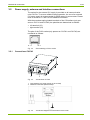
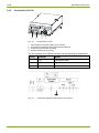
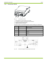
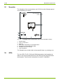
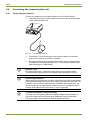
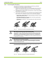
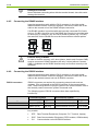
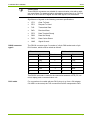
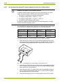
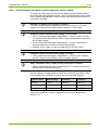
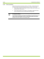
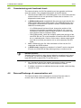
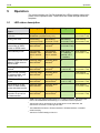
24/38 Installation/De-installation 4.4.5 Damage to terminals Never withdraw connecting wires with the terminal closed, since this could damage the terminal. Connecting the RS485 interface Insert the connecting cable with the RJ12 connector in the right socket labelled RS485 until the connector engages. Connect the other end of the cable to the nearest unit of the RS485 multiple connection. If its RS485 interface is provided with two internally connected RJ12 sockets (e.g. CU-B2), the other end of the RS485 bus can also be provided with an RJ12 plug. If, however, only one RJ12 socket is present (e.g. CU-P42) the extension for the RS485 bus must be formed with an external splitter. External wiring of RS485 In order to function correctly, all 3 wires (data a, data b and Common GND) must be connected. RS485 operation with only 2 wires (without Common GND) is forbidden as the RS485 interface may not function correctly or be damaged. 4.4.6 Connecting the RS232 interface Insert the connecting cable with the RJ12 connector in the right socket labelled RS232 until the connector engages. Connect the other end of the cable to the desired external unit via an RS232 converter. RS232 converters RS232 converters are required for connecting external units such as modems, PCs and laptops to the RS232 interface of the communication units. These convert the RJ12 plug-in system of the communication units to the normally used D-connector system of external units. The following types of RS232 converters have been specified by Landis+Gyr: D-connector system RJ-connector system Converter type Connection for D-type Connection for RJ-type C Computer (DTE) DB9 socket Communication unit (CU) RJ12 socket F Modem (DCE) DB9 plug Communication unit (CU) RJ12 socket Key to table: © Landis+Gyr DTE DCE Data Communication Equipment (PSTN modem, GSM modem) CU Data Terminal Equipment (Computer: PC, Terminal, Laptop) Communication unit with RS232 interface D000043188 en a – E65C – CU-P40, P41, P42 – User Manual