1
XRT83SL30/L30EVAL User Manual
EVALUATION KIT PART LIST
This kit contains the following:
• XRT83SL30/L30EVAL Application Board
• XRT83SL30/L30 GUI Evaluation Software
• XRT83SL30/L30 64-Pin TQFP
• XRT83SL30/L30EVAL User Manual
• XRT83SL30/L30 Datasheet
FEATURES
•
•
•
•
•
•
25 DIN Connector for Easy Connection Through a Standard Parallel Port to a PC
CD ROM or Floppy Disk Containing the GUI Software (Executable File)
Line Interface Modules Coupled to the Receiver Inputs and Transmitter Outputs
Power Supply Design Allowing a Single 3.3V Supply voltage
Accessible I/O Interface for Common Laboratory Equipment
Optimized layout with Four Layers
INTRODUCTION
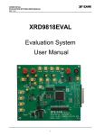
The XRT83SL30/L30EVAL is a complete printed circuit board for characterizing Exar’s
XRT83SL30/L30. The XRT83SL30/L30 is a fully integrated single channel, long haul, short haul
line interface unit for T1, E1 or J1 applications.
This application board combines a proven PC board layout with optimized analog and digital
interface circuitry. The XRT83SL30/L30EVAL contains the device being tested, line interface
modules coupled to the receiver inputs and transmitter outputs, and I/O headers for a flexible
user interface. Complete AC and DC performance of the XRT83SL30/L30 can be evaluated by
interfacing external laboratory equipment.
SYSTEM CONFIGURATION-LAB SETUP
The XRT83SL30/L30EVAL application board is setup as a common test circuit. Figure 1 shows a
simplified block diagram of the default test configuration.
XRT83SL30/L30 PCB
Connector Connector
TPOS
TNEG
TCLK
RPOS
XRT83SL30
XRT83L30
LIU
Parallel Port Cable
25 DIN Connector
CPLD
TTIP
TRING
Connector
RNEG
RCLK
5
CS
SCLK
SDI
SDO
HW_Host
INT
RESET
ICT
RTIP
RRING
Connector
PC
Figure 1 Simplified Block Diagram of the XRT83SL30/L30EVAL Application Board
Page 2 of 21