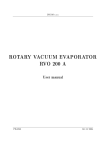
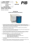
1
INGOS Ltd.
SPECTROPHOTOMETRIC
DETECTOR
LCD5000
User manual
PRAGUE
Apr 11 2006
Producer
:
Laboratory Instruments division of INGOS Ltd.
Development
:
PiKRON Ltd.
Supplier and service
:
INGOS Ltd.
K Nouzovu 2090
14316 PRAGUE 4
CZECH REP.
(c) INGOS 2006
Tel: +420 296 781 683
+420 296 781 692
Fax: +420 244 403 051
e-mail:[email protected]
INTRODUCTION
CAPABILITIES AND SPECIFICATIONS
PUTTING INTO OPERATION
SERVICE
DESCRIPTION OF FUNCTION
ACCESSORIES AND REPLACEMENT PARTS
WARRANTY
TABLE OF CONTENTS
1
2
3
4
5
6
7
8
1. INTRODUCTION
Detector fitted with an analytical cell is designed for analytical and semi-preparative
liquid chromatography. If the cell is exchanged, the detector can be used for preparative
chromatography and micro-column chromatography.
Furthermore, the detector is usable for the measuring of absorbency in the throughflow cell everywhere, where it is possible to draw a sample into the cell and measure the
absorbency value, both at a single wavelength and for a partial spectrum.
A two-line display together with a 36-key membrane keyboard provide user’s comfort
for both direct control purposes and program control. In addition to the control of the
detector itself the program can also control additional equipment designed e.g. for fraction
collector, etc.
The detector is constructed as an independently functioning apparatus, and it can be
connected to a centrally controlled purposeful assembly consisting of more apparatuses.
Serial contacts make it possible to connect more apparatuses into a complete assembly
for HPLC or for other purposes. They also make it possible to control and assess the
entire assembly by using a master computer. Besides serial contacts, the apparatus is
fitted with a connector with TTL signals for the control of peripheries which do not have
any processor built-in.
This manual describes installation, operation, troubleshooting, maintenance and service instructions for the detector LCD5000.
INGOS s.r.o.
Page 4
1
2. CAPABILITIES AND SPECIFICATIONS
2.1 Capabilities
Optical assembly with a high optical gain fitted with modern electronic equipment
and software provides large application possibilities without the apparatus having to be
treated.
Detector with a variable wavelength within a range of 190 - 370 nm fitted with a
standard deuterium discharge lamp.
Detector with a variable wavelength within a range of 360 - 700 nm fitted with a
discharge lamp.
Detector with a variable wavelength within a range of 190 - 700 nm fitted with a
built-in deuterium lamp and halogen lamp.
Analytical detector for high-performance liquid chromatography (HPLC) with a standard stainless steel through-flow cell featuring an optical length of 5 mm and a volume
of 5 µl or micro cell optical length of 4 mm and a volume of 2 µl (Optional).
Detector pro semi-preparative and preparative chromatography with a through-flow
cell (silica - Teflon) featuring an optical length of 0.2 mm and a volume of 10 µl. (Optional)
2.1.1 Data transmission
Detector transmits data along a serial line and at the same time along an analogue
line for recorder.
Detector is fitted with the communication system RS485 and alternatively also with
RS232.
For the purpose of controlling its optional equipment without their own intelligent
systems the detector is fitted with the outputs including retrospective controls (TTL level
signals).
INGOS s.r.o.
Page 5
2
LCD5000
Section 2: CAPABILITIES AND SPECIFICATIONS
2.1.2 Specications
Wavelength range . . . . . . . . . . . . . . . . . . . . . . . . .190 to 370 nm with a deuterium
discharge lamp
360 to 700 nm with a halogen lamp
190 to 700 nm with a discharge
lamp and halogen lamp
Scanning . . . . . . . . . . . . . . . . . . . . . . . . . . . . . . . . . 60 wavelengths / min.
Wavelength accuracy . . . . . . . . . . . . . . . . . . . . . 1 nm
Wavelength reproducibility . . . . . . . . . . . . . . . 0.1 nm
Half-width . . . . . . . . . . . . . . . . . . . . . . . . . . . . . . . . < 4 nm
Measurement range . . . . . . . . . . . . . . . . . . . . . . . -1 to 2 AU
Noise . . . . . . . . . . . . . . . . . . . . . . . . . . . . . . . . . . . . . 1.10−5 AU at time const. 1 sy
Drift . . . . . . . . . . . . . . . . . . . . . . . . . . . . . . . . . . . . . 5.10−4 AU/hy
Time constant value . . . . . . . . . . . . . . . . . . . . . . 0.04 to 2.5 s
Analogue output . . . . . . . . . . . . . . . . . . . . . . . . . . 1 V with resolution 15 bit
software makes it possible to assign ranges
0.01, 0.02, 0.05, 0.1, 0.2, 0.5,
1, 2 AUFS
Output for computer . . . . . . . . . . . . . . . . . . . . . RS485 alternatively RS232
Automatic resetting . . . . . . . . . . . . . . . . . . . . . . key or program command
Control signals
inputs . . . . . . . . . . . . . . . . . . . . . . . . . . . . . . . . . 2 (TTL level)
outputs . . . . . . . . . . . . . . . . . . . . . . . . . . . . . . . . 4 (TTL level)
Standard analytical cell
optical length . . . . . . . . . . . . . . . . . . . . . . . . . . 5 mm
volume . . . . . . . . . . . . . . . . . . . . . . . . . . . . . . . . 5 µl
Dimensions (w x h x d) . . . . . . . . . . . . . . . . . . . 240 x 130 x 400 mm
Weight . . . . . . . . . . . . . . . . . . . . . . . . . . . . . . . . . . . 7.5 kg
Power supply . . . . . . . . . . . . . . . . . . . . . . . . . . . . . 110 to 230 V, 10%, 50 to 60 Hz
Overvoltage category in the installation . . . II.
Power input . . . . . . . . . . . . . . . . . . . . . . . . . . . . . . 100 VA
y Noise and drift measured 1 h after turning on, dry cell, temperature drift 0.5 oC
with a standard cell (5 µl, 5 mm) and a wavelength of 254 nm
The apparatus is designed for the environment featuring a temperature of 15 to 35 o C;
humidity up to 80% without any vapours of acids and caustic substances.
Any use of the apparatus other than the use provided for in this manual could endanger the operation safety.
INGOS s.r.o.
Page 6
2
3. PUTTING INTO OPERATION
3.1 Unpacking
Unpack the detector carefully from the transport package. Check the external parts
of the apparatus for damage having possibly occurred during transportation. If you find
any damage, contact the carrier.
The manufacturer’s plate is located on the internal side of the cell door.
Check all items according to the Packing Note (6.1). If the real number does not
correspond to the Packing Note, check thoroughly all packing material. If an item is
missing, contact the manufacturer or your supplier.
Put the detector on the table and make yourself familiar with the distribution and
functions of the control and connection items.
The equipment does not impose any requirements on additional ventilation.
3.2 What you need
For the putting into operation of the detector you will need the following items:
1. A pipe for the connection of the cell to the chromatography zone and a pipe designed
for the offtake of the acid flowing out from the cell. It is usually made from the
material TEFLON, external diameter 1/16”, internal diameter 0.25 mm and passing
screws for the pipe connections.
2. Computer fitted with the assessment program and a converter for the detector connection.
3. Pump, dispensing valve, chromatography column.
Note: If Teflon pipes are used, the pipes must be fitted, in a length of 50 mm in front
of the cell, with a light-impermeable cover, so that the external light shall not influence
the measurement. Black tubing can be optimally used as a cover.
3.3 Control and connection items
3.3.1 Cell
The cell is accessible through the door situated on the left side of the apparatus, and
it can be taken away after the loosening of the two nuts and removal of the photocell. The
orientation of the cell inlets according to fig. 1 is the only one that operates, when the
inlet is situated on a bottom part. The pipes shall be led through the cuttings situated
next to the door.
3.3.2 Rear panel
The following elements are situated on the rear panel (fig. 2):
Main switch.
Main fuse T 1.6A. Use always a fuse of the same type while making a replacement.
The mains inlet for the connection of a power supply cord. The apparatus features
an impulse power supply source which ensures the power supply of 110 to 230 V 50 as
well as 60 Hz.
INGOS s.r.o.
Page 7
3
LCD5000
Section 3: PUTTING INTO OPERATION
1
2
3
3
4
5
1. Photometer body
2. Cell
3. Photometer probe
4. Inlet into the cell
5. Fastening nuts
Fig. 1. Cell
1
1.
2.
3.
4.
2
Power supply switch
Power supply fuse
Power supply inlet
Connector Aux Output
3
4
5
6
7
5. Connector RS232 (special equipment)
6. Two connectors RS485
7. Connector of the analogue output designed for the recorder
Fig. 2. Rear panel
The connector AUX OUT for the connection of TTL outputs and inputs.
Connector RS232. As a standard it is not fitted, its fitting is made on an optional
basis.
INGOS s.r.o.
Page 8
LCD5000
Section 3: PUTTING INTO OPERATION
Two connectors RS485. These connectors are connected in a parallel manner. They
serve for the computer connection of the detector. The connectors are two so that it can
be possible to connect more apparatuses to a single communication channel. The detector
will be connected through a special converter to the computer serial port. the converter
is a part of the delivery of the computer software. A typical example of interconnection
of the chromatography system is illustrated in fig. 3.
The REC connector is an analogue output for the connection of the recorder or the
integrator with an analogue input. The voltage level of the signal is 1V.
3
1
7
2
3
8
4
9
5
6
1.
2.
3.
4.
5.
6.
10
Computer
Computer power supply
Keyboard connection
Monitor connection
Mouse connection
Converter RS232/RS485
7. Detector
8. Pump
9. Interconnection of the communication
system RS485
10. Pump and detector power supply
Fig. 3. Example of the chromatography system interconnection
All connectors are mutually non-interchangeable and thereby there is no danger of
damage to the detector or periphery equipment connected if you are using the interconnection cables delivered by the manufacturer.
3.3.3 Keyboard and display
The actual control shall be carried out by using the keyboard situated on the front
panel, the information being displayed on the display which is a part of the keyboard.
The meaning of individual keys is as follows:
INGOS s.r.o.
Page 9
LCD5000
Section 3: PUTTING INTO OPERATION
UV LAMP HIGH UV LAMP LOW switches the deuterium discharge lamp on see
4.1.1.
LAMP OFF switches the deuterium discharge lamp off see 4.1.1.
VIS LAMP switches the halogen lamp on and off see 4.1.1.
09 PREAMP TEST Switches over to the mode PREAMP TEST see 4.1.5.
RUN activates the program control of the cycle, if the program is situated in the
internal memory.
HOLD suspends the run of the program.
END interrupts the run of the program and returns all time-depending values to
the conditions as they were set by the program at the time 0.00 and this applies even in
the case of direct control (see 4.1).
SPECTROPHOTOMETRIC DETECTOR
**
IMPL
PROG
7
8
9
4
5
6
2
3
ABS
ATTEN
AUX
OUTPUT
CYCLE
LIST
HELP
INSERT
LINE
DFELETE
LINE
MODE
1
RUN
HOLD
END
UV
LAMP
HIGH
UV
LAMP
LOW
VIS
LAMP
LAMP
OFF
PREAMP
TEST
MARK
0
ENTER
LCD 5000
Fig. 4. Keyboard
PROG switches the control mode over to the program editing
MODE modification of the configuration of the pump, assembly, operation
1 to 0 and . entering of numerical data.
ENTER keyboard for the confirmation of the number entered, possibly for the
selection from the menu.
direction keys for the movement of cursor under individual positions of
the display.
HELP will provide current user’s information. If you press twice, you will call the
operating instructions for using the HELP instructions. If you are using the HELP comare active. The direction keys enable you to
mand, the keys ENTER and
make a choice by moving cursor, by your pressing ENTER the selected items will be
confirmed.09
LIST makes it possible to carry out the inspection of the program list and the selection of one of them for activation or editing. If only one program has been programmed,
it is not possible to use this function.
INGOS s.r.o.
Page 10
3
LCD5000
Section 3: PUTTING INTO OPERATION
CYCLE AUX OUTPUT ATTEN ABS these keys are used for the switching
over of individual displays.
CTRL INSERT LINE DELETE LINE these keys are used during the preparation of the program. ??
3.4 Switching the apparatus on
Procedure during your switching the apparatus on is as follows:
1. Perform electrical connection of the apparatus, see 3.3.2
2. Connect the cell input and output, see 3.3.1.
3. Turn the apparatus on by using the switch situated on the rear panel, see fig. 2 and
wait until the internal checks are completed
4. When you see the basic display, set the wavelength and time constant value, see 4.1.2.
5. Turn on the lamp of a corresponding wavelength, see 4.1.1.
6. Turn on the computer and activate the integration software.
7. After stabilising initial conditions reset absorbency by using the key ZERO .
8. The apparatus is ready to measure.
INGOS s.r.o.
Page 11
3
4. SERVICE
All functions of the apparatus are controlled with the help of the keyboard and the
display situated on the front panel. The apparatus can be controlled in several modes.
They are based on direct control, program run and program editing. Individual modes
are described below.
All control modes have certain common characteristics. This concerns:
1. Cursor movement. It is possible to move the cursor by using the keys
.
Cursor does not move by individual characters but by the items.
2. Entering numerical data. It is impossible to change the item under which the cursor
is situated. Numerical data is entered by using numerical keys. If it is necessary to
enter a negative number, use the key CTRL. After entering it is necessary to confirm
the number by using the key ENTER .
3. Choice from the menu. If you are choosing from the menu, move cursor to the item
required and carry out the choice by using the key ENTER İf the menu is longer,
you will see only two lines on the display, and during the cursor movement the menu
scrolls.
4.1 Direct control
4.1.1 light sources
The detector made in the UV-VIS design has two light sources. They are a deuterium
lamp and a halogen lamp. The detector in the UV design is fitted with a deuterium
discharge lamp only.
The deuterium discharge lamp is used for the measurement in the UV range from
190nm to 370nm. The discharge lamp is turned on by using the keys UV LAMP HIGH or
UV LAMP LOW , it will be turned off by using the key LAMP OFF. After turning
on, the discharge lamp will first be heated while the LED is flashing, then the discharge
lamp starts lighting and the LED is permanently lit.
The modes HIGH and LOW differ from each other by the current of the discharge
lamp, the quantity of light corresponds to the current and it is connected with a corresponding level of noise noise as well. The lifetime of the lamp depends on the value of
the current.
The mode HIGH (current is 150mA) is convenient where it is necessary to have a
minimum noise, especially during the measurement at the wavelengths on the margin of
the range where the level of the light is lower. A disadvantage is a lower lifetime of the
lamp in this case.
The mode LOW (current is 100mA) is advantageous in the installations where it is
necessary to save the discharge lamp, and the signal is so high that the increase in noise
will not influence the accuracy of the measurement.
The manufacturer states the lamp lifetime as 1000 hours at a current of 300mA. Even
in the mode HIGH the lamp lifetime is several times higher.
INGOS s.r.o.
Page 12
4
LCD5000
Section 4: SERVICE
The halogen lamp serves for the measurement in the area of VIS from 360nm to
700nm. The lamp is switched on by using the key VIS LAMP, by pressing this key
again you will switch it off. The fact that the lamp has been switched on is indicated
through a LED on the keyboard.
If both of the two light sources are switched on at the same time, the linearity during
the measurement above 370nm is distorted at absorbency values higher than 0.2AU.
Therefore it is necessary to switch the discharge lamp off during the measurement above
370nm.
Both sources at the same time are used mainly for scanning through the entire
spectrum, when no exact quantitative assessment is necessary.
4.1.2 Basic display
This display will be activated by using the key ABS .
ABS 0.123456 -l 240nm t 1.00s
The following data will appear on the display:
ABS
Absorbency. By using the key ZERO it is possible to reset (zero) the absorbency value.
l
Set the wavelength. The wavelength can be pre-set within a range from 0
to 700 nm. For other details see 4.1.1. If the setting phase is underway, the
display reads as follows Wrk.
t
Time constant value. The time constant value can be pre-set within an interval
from 0.04 to 2.50 s.
4.1.3 Analogue output setting
The display for the pre-setting of the output to be used for the analogue recorder or
integrator will be activated if you press the key ATTEN .
ABS 0.123456 AU
0.5 AUFS : 2.00
The display contains the following data:
ABS
Absorbency. By pressing the key ZERO it is possible to reset (zero) the
absorbency value.
AUFS
The first number specifies how many absorbency units belong to the entire
range of the recorder. The second number is the reciprocal value of the first
number. It states the factor with which the output signal is multiplied. By
and
it is possible to set the range in firmly defined steps.
using the keys
While setting the range on Usr, it is possible to pre-set also the multiplication
factor (the second number) on an arbitrary basis.
INGOS s.r.o.
Page 13
4
LCD5000
Section 4: SERVICE
4.1.4 control inputs and outputs
By using the key AUX OUTPUT you will activate the display used for controlling
input commands and reading their feedback responses.
AUX
-SOUTPUT 1234
-R56
On the display you will read the following data:
-SInput commands. They are controlled by means of a numerical keyboard where
the pressing of the keys 1 to 4 will initiate the command and a new pressing
of the same will cancel it.
-R. Only the feedback responses are displayed.
4.1.5 Preamp test
This test serves for the testing of the discharge lamp, verification of electronic equipment and for the verification of a luminous flux by reference and the cell. It will be called
by the key PREAMP TEST .
Preamp test Exit
ABS 0.123456 -l 250nm t 1.00s
Wlen Offs
0
Offs -0.049662
Ref ADC
17896
Save service
In the place of the ABS value also other data can be displayed (CUV REF RAT NUL).
The display of individual data items shall be switched over by using the key ENTER, if
cursor is situated on the item ABS.
The meaning of individual data is as follows.
Exit
Escape from the mode preamp test.
ABS
Absorbency.
CUV
Light by the cell. Max 0.95.
REF
Light by the reference. Max 1.5. This data item serves for the control of
the lamp and discharge lamp. See 4.2.1
RAT
Ratio of CUV/REF. Max 0.95.
NUL
Zero of the amplifier.
l
Wavelength pre-set. The wavelength can be adjusted within a range from
0 to 700 nm. For other details see 4.1.1. If the adjustment is being carried
out, the display reads Wrk.
t
Time constant value. The time value can be adjusted within a range from
0.04 to 2.50 s.
INGOS s.r.o.
Page 14
4
LCD5000
Section 4: SERVICE
Wlen Os
Offset of the wavelength. This constant is adjusted by the manufacturer or
servicing technicians during the adjustment of the apparatus.
Os
Offset of the converter. This constant is adjusted by the manufacturer or
servicing technicians during the adjustment of the apparatus.
Ref ADC
Value of the auxiliary reference converter. It serves for the servicing purposes.
Save service Servicing information storage.
4.2 Routine maintenance
The detector LCD5000 does not require any maintenance other than the cleaning of
the surface. It shall be carried out with the help of a cloth moistened in soap water.
During the connection of the cell, see 3.3.1 it is necessary to carry out a careful
inspection for leakage of the pipe connection to the cell at the first activation with a
through-flowing liquid. This inspection is still to be carried out after a several-hour-long
operation. Any liquid which could possibly leak shall be collected on the bottom of the cell
box. Any possible leakage shall be removed by means of the tightening of the concerned
connection. The liquid which has escaped shall be fully removed by wiping.
4.2.1 Inspection of lamps
By using the function PREAMP TEST (4.1.5) you can control the intensity of the
light in the reference branch (REF). Thereby you can assess the ageing of the lamps.
The deuterium lamp shall be controlled at a wavelength of 250 nm. If the intensity of
the light drops to one half, or if the lamp starts burning unevenly (the value is oscillating),
it is necessary to replace the lamp. The manufacturer of the deuterium lamp guarantees
a reduction of the luminous flux to one half after 1000 hours at a current of 300 mA.
The halogen lamp shall be inspected at a wavelength of 360nm. If the lamp features
unstable behaviour at this wavelength, it needs replacing.
4.3 Troubleshooting
4.3.1 Problems with the cell
With the help of the function PREAMP TEST (4.1.5) you can identify the absolute
value of the light, passing through the cell. If the intensity of the light is low, and there
is enough light on the reference, it signalises that the cell has been contaminated.
Cleaning can be carried out by using a syringe, with the help of a liquid current.
While cleaning, you can use connection pipes whose clearance is 0.8 mm. Choose suitable
liquid according to the type of contamination.
If the rinsing with a liquid current does not help, it will be necessary to disassemble
the cell and carry out mechanical cleaning of the cell body and lenses. The lenses can
be cleaned only with wadding, it is also possible to use alcohol denatured with petrol or
ether. The cell assembly is illustrated in Figure fig. 5.
4.3.2 large noise
Large noise could be caused by impurities in the cell or by a shortage of the light.
INGOS s.r.o.
Page 15
4
LCD5000
Section 4: SERVICE
1.
2.
3.
4.
5.
6.
1
2
3
Monochromatic device
Cell pad
Cell body
Lenses
Internal area of the cell
Photo-metering probe
Cell cross-section
4 Fig.5 5. 6
By using the function PREAMP TEST (4.1.5) you can find out the reference and
cell intensities of the light. If the reference contains a sufficient light intensity, there are
impurities in the cell, and you should follow the procedure according to 4.3.1. If there is
little light in the reference, it could be caused by your using a bad lamp for the wavelength
in question (see 4.1.1), or by a bad lamp in general. Follow the instructions in 4.3.3
4.3.3 Little light
If you think that the intensity of the light is low, carry out an inspection of the lamps
according to 4.2.1. If it is necessary to replace a lamp , follow the instructions provided
for in 4.3.4 or 4.3.5.
4.3.4 Discharge lamp replacement
If you are replacing the discharge lamp, follow the below described procedure. In fig. 6
you can see the location and connection of the discharge lamp.
Caution Hold the discharge lamp always at its base part, never touch the glass of the
discharge lamp. If you contaminate the discharge despite these precautions, clean it with
alcohol.
Replacement procedure:
1. Turn the apparatus off and disconnect it from the mains.
2. Unscrew the two screws holding the rear cover and remove the cover.
3. Disconnect the discharge lamp from terminals.
4. Unscrew the two nuts and remove the discharge lamp with the holder.
5. Release the socket on the holder, and remove the discharge lamp.
6. Insert a new discharge lamp into the holder, turn it in such a way that the outlet port
of the discharge lamp will be in the same direction as the outlet port of the holder.
7. Fix the discharge lamp in the holder by tightening the socket.
INGOS s.r.o.
Page 16
4
LCD5000
Section 4: SERVICE
1
2
3
4
1. Discharge lamp base
2. Socket used for the attachment of the
discharge lamp in the holder
3. Discharge lamp holder
5
4. Nuts serving for the attachment of the
discharge lamp holder
5. Terminal board used for the connection
of the discharge lamp
Fig. 6. Discharge
8. Mount the discharge lamp holder on the detector holder. Be sure not to forget about
the flexible washer under nuts, otherwise it will not be possible to adjust the discharge
lamp.
9. Tighten the nuts only partially, in such a way that the discharge lamp can be moved.
10. Connect the discharge lamp to terminals. The red wire must be connected to the
terminal identified in a red colour.
11. Turn the apparatus on and switch on the discharge lamp.
12. Adjust the wavelength at a value of 250nm.
13. With the help of the function PREAMP TEST (4.1.5) observe the intensity of the
light in the measurement branch (CUV).
14. Move the discharge lamp upwards and downwards, as well as to the sides so that the
light intensity can be as large as possible.
15. Tighten the nuts for the discharge lamp to be fixed.
16. Release the discharge lamp socket so that it will be possible to rotate the discharge
cell .
17. Rotate the discharge lamp carefully and search for a maximum intensity of the light.
18. Tighten the socket again.
19. Reassemble the rear cover.
INGOS s.r.o.
Page 17
4
LCD5000
Section 4: SERVICE
4.3.5 Lamp replacement
If you are replacing the lamp, observe the following instructions. In the fig. 7 you can
see the location and connection of the lamp.
Caution Hold the lamp always at its base part, never touch the glass of the lamp. If
you contaminate it, despite these precautions, clean it with alcohol.
4
1
2
3
4
1. Lamp
2. Discharge lamp
3. Terminal board for the connection of
the discharge lamp
4. Terminal board for the connection of
the lamp
Fig. 7. Location of the lamp and discharge lamp
1.
2.
3.
4.
5.
6.
7.
Turn the apparatus off and disconnect it from the network.
Unscrew the two screws holding the rear cover and remove the cover.
Unscrew the four screws holding the upper cover and remove the cover.
Disconnect the lamp from the terminals.
Unscrew the two screws holding the lamp and remove the lamp.
Insert the new lamp and screw it. It is not necessary to adjust the lamp.
Mount the upper and rear covers.
INGOS s.r.o.
Page 18
5. DESCRIPTION OF FUNCTION
5.1 Optics
The optical set is constructed in such a way that it can ensure the adjustment of
the wavelength as exactly as possible and at the smallest half-width possible. The use of
lenses and mirrors made of high-quality silica glass ensures that the loss of light will be
very small even on the short wavelengths (about 200nm).
Optical set (fig. 8) consists of the following parts:
Light source. In order that the apparatus will be able to work in the entire spectrum of
wavelengths, the source is formed by two lamps. They are the deuterium discharge lamp
for wavelengths below 370nm and the halogen lamp used for wavelengths above 360nm.
In order to achieve a maximum evenness of the luminous flux over the entire spectrum,
the combination of the light coming from individual lamps uses a special semi-permeable
mirror tailored to our apparatus. In order to improve the evenness still more, a filter has
been inserted in front of the halogen lamp. This filter serves also for the de-filtration of
short wavelengths originating from the lamp light, which could result in measurement
inaccuracies in a visible area, see 4.1.1.
Rotary, attached holographic grille. This grille serves for the wavelength selection. A
top-quality grille produced by the firm Karl ZEISS has been selected. This grille ensures
a small half-width and an exact adjustment of the wavelength.
1
2
3
4
5
6
1. Deuterium discharge lamp
2. Semi-permeable mirror of the combination device
3. Filter
4. Halogen lamp
5. Input lens
6. Input slot
7. Reference photodiode
7
8
9
10 11 12 13
8. Output reference diaphragm
9. Semi-permeable mirror of the separator
10. Output diaphragm of the measurement
branch
11. Cell
12. Measurement photodiode
13. Grille
Fig. 8. Optical chart of the detector
INGOS s.r.o.
Page 19
5
LCD5000
Section 5: DESCRIPTION OF FUNCTION
Separator for the division of the light into the measurement and reference branches.
This separator is formed by a special, semi-permeable mirror which ensures good properties for all wavelengths.
Detection photodiodes for the measurement and reference branches. The apparatus
uses PIN photodiodes featuring a high sensitivity also for short wavelengths.
5.2 Mechanics
From the mechanical point of view the detector is constructed in such a way that it
can provide wide possibilities despite its small dimensions. The construction also followed
the possibilities of servicing.
The mechanical parts of the detector consist of the following items:
Case. The case is made of hard aluminium and constructed in such a way that it can
be as light as possible while keeping its maximum stiffness. The front panel is formed
by a standard plastic pressed piece, similarly as in the case of other apparatuses of this
series (pump, dispenser).
The monochromatic unit ensures, through its robust construction, high stability of
the measuring system.
Wavelength adjustment mechanism. This mechanism is driven by a stepping motor
which rotates the micrometric screw. The nut of the micrometric screw moves the lever
connected with a grille. This mechanism provides for the function arcsin. This function
is required for the transmission between the motor steps and the wavelength to be linear.
The connection between the stepping motor and the micrometric screw ensures an exact
adjustment of the wavelength 1nm and the reproducibility of adjustment 0.1nm.
5.3 Electronics
Electronic parts of the detector are designed with regard to the use of modern procedures, they consist of top-quality parts. The design is optimised in such a way that
high stability and reliability of the entire apparatus can be ensured.
The electronic system can be divided into the following parts:
Impulse mains source. The input voltage of the source can be 110 to 230V, 50 to
60Hz. The output voltage is 24V. All other units are constructed to a voltage of 24V.
Voltage source for the discharge lamp and lamp. The source for the discharge lamp
is an impulse converter featuring an input voltage level of 24V and output voltage level
of 5.3V 2A. The discharge lamp source consists of two parts, actual source and auxiliary
source for heating. The actual source is of a current type, 100 or 150mA, maximum
voltage level being 100V. The heating source is of a voltage type, 6 or 10V 2A. During
the ignition phase it is necessary to use a higher voltage, during operation the discharge
lamp is heated with a lower voltage. The sources are controlled by means of a control
unit.
Control unit. This unit ensures the control of the entire apparatus, its basic part is
represented by the processor Siemens 80C517. 32kB of EPROM memory and 32kB of
RAM memory is connected to the processor. The RAM memory serves as a storage area
for user’s programs, that is why it features a battery backup.
INGOS s.r.o.
Page 20
5
LCD5000
Section 5: DESCRIPTION OF FUNCTION
A/D converter is of a special construction, 24 bits. The converter operates at a speed
of 25 samples per second.
Keyboard and display. The keyboard has 36 keys, some of them are completed with an
indication LED. Its display is represented by an intelligent LCD featuring a background
illumination facility, it has two lines by 16 characters.
5
INGOS s.r.o.
Page 21
6. ACCESSORIES AND REPLACEMENT PARTS
6.1 Basic accessories
1 item Mains cord
1 item Communication cable RS485
2 items Fuse T 1.6 A
2 items Through-bolt UNF10 PEEK
6.2 Other accessories and replacement parts
Furthermore it is possible to order these accessories and replacement parts:
Halogen lamp
Discharge lamp, deuterium
Through-bolt UNF10 PEEK
Pipe 1/16”/0.25mm TEFLON
Preparative cell
Analytical micro cell
6
INGOS s.r.o.
Page 22
7. WARRANTY
The manufacturer provides a one-year warranty period for the detector LCD5000
which starts running from the day when the product is handed over to the customer.
The apparatus can only be used in the way provided for in these instructions. The manufacturer is not liable for any damage arising as a result of a failure to comply with the
conditions provided for in the instructions.
This warranty does not cover the deuterium discharge lamp and the halogen lamp.
The apparatus is designed for the environment featuring a temperature of 15 to 35
0
C; its humidity being up to 80% without any vapours of acids and caustic substances.
The operators must be made familiar with applicable safety regulations and with the
methods of work with the liquids used.
All warranty and after-warranty repairs shall be made by the manufacturer or by the
organisation authorised by the latter. Unless the delivery note provides for otherwise,
contact the manufacturer if you have any request concerning repairs.
7.1 Waste disposal
When the instruments operating life is over dispose it in respect to valid regulations,
also it can be returned to the vendor or producer for liquidation.
Warning: Instrument contains parts (PCB’s) which are rated as hazardous waste.
7
INGOS s.r.o.
Page 23
8. TABLE OF CONTENTS
1. INTRODUCTION . . . . . . . . . . . . . . . . . . . . . . . . . . . . . . . . . . . . . . . . . . . . . . . . . . . . . . . . . . . . . 4
2. CAPABILITIES AND SPECIFICATIONS . . . . . . . . . . . . . . . . . . . . . . . . . . . . . . . . . . . . . . 5
2.1 Capabilities . . . . . . . . . . . . . . . . . . . . . . . . . . . . . . . . . . . . . . . . . . . . . . . . . . . . . . . . . . . . . . 5
2.1.1 Data transmission . . . . . . . . . . . . . . . . . . . . . . . . . . . . . . . . . . . . . . . . . . . . . . . . . . 5
2.1.2 Specifications . . . . . . . . . . . . . . . . . . . . . . . . . . . . . . . . . . . . . . . . . . . . . . . . . . . . . . 6
3. PUTTING INTO OPERATION . . . . . . . . . . . . . . . . . . . . . . . . . . . . . . . . . . . . . . . . . . . . . . . . 7
3.1 Unpacking . . . . . . . . . . . . . . . . . . . . . . . . . . . . . . . . . . . . . . . . . . . . . . . . . . . . . . . . . . . . . . . . 7
3.2 What you need . . . . . . . . . . . . . . . . . . . . . . . . . . . . . . . . . . . . . . . . . . . . . . . . . . . . . . . . . . . 7
3.3 Control and connection items . . . . . . . . . . . . . . . . . . . . . . . . . . . . . . . . . . . . . . . . . . . . . 7
3.3.1 Cell . . . . . . . . . . . . . . . . . . . . . . . . . . . . . . . . . . . . . . . . . . . . . . . . . . . . . . . . . . . . . . . . 7
3.3.2 Rear panel . . . . . . . . . . . . . . . . . . . . . . . . . . . . . . . . . . . . . . . . . . . . . . . . . . . . . . . . . 7
3.3.3 Keyboard and display . . . . . . . . . . . . . . . . . . . . . . . . . . . . . . . . . . . . . . . . . . . . . . 9
3.4 Switching the apparatus on . . . . . . . . . . . . . . . . . . . . . . . . . . . . . . . . . . . . . . . . . . . . . . 11
4. SERVICE . . . . . . . . . . . . . . . . . . . . . . . . . . . . . . . . . . . . . . . . . . . . . . . . . . . . . . . . . . . . . . . . . . . . . 12
4.1 Direct control . . . . . . . . . . . . . . . . . . . . . . . . . . . . . . . . . . . . . . . . . . . . . . . . . . . . . . . . . . . 12
4.1.1 light sources . . . . . . . . . . . . . . . . . . . . . . . . . . . . . . . . . . . . . . . . . . . . . . . . . . . . . . 12
4.1.2 Basic display . . . . . . . . . . . . . . . . . . . . . . . . . . . . . . . . . . . . . . . . . . . . . . . . . . . . . . 13
4.1.3 Analogue output setting . . . . . . . . . . . . . . . . . . . . . . . . . . . . . . . . . . . . . . . . . . 13
4.1.4 control inputs and outputs . . . . . . . . . . . . . . . . . . . . . . . . . . . . . . . . . . . . . . . . 14
4.1.5 Preamp test . . . . . . . . . . . . . . . . . . . . . . . . . . . . . . . . . . . . . . . . . . . . . . . . . . . . . . . 14
4.2 Routine maintenance . . . . . . . . . . . . . . . . . . . . . . . . . . . . . . . . . . . . . . . . . . . . . . . . . . . . 15
4.2.1 Inspection of lamps . . . . . . . . . . . . . . . . . . . . . . . . . . . . . . . . . . . . . . . . . . . . . . . 15
4.3 Troubleshooting . . . . . . . . . . . . . . . . . . . . . . . . . . . . . . . . . . . . . . . . . . . . . . . . . . . . . . . . . 15
4.3.1 Problems with the cell . . . . . . . . . . . . . . . . . . . . . . . . . . . . . . . . . . . . . . . . . . . . 15
4.3.2 large noise . . . . . . . . . . . . . . . . . . . . . . . . . . . . . . . . . . . . . . . . . . . . . . . . . . . . . . . . 15
4.3.3 Little light . . . . . . . . . . . . . . . . . . . . . . . . . . . . . . . . . . . . . . . . . . . . . . . . . . . . . . . . 16
4.3.4 Discharge lamp replacement . . . . . . . . . . . . . . . . . . . . . . . . . . . . . . . . . . . . . . . 16
4.3.5 Lamp replacement . . . . . . . . . . . . . . . . . . . . . . . . . . . . . . . . . . . . . . . . . . . . . . . . 18
5. DESCRIPTION OF FUNCTION . . . . . . . . . . . . . . . . . . . . . . . . . . . . . . . . . . . . . . . . . . . . . 19
5.1 Optics . . . . . . . . . . . . . . . . . . . . . . . . . . . . . . . . . . . . . . . . . . . . . . . . . . . . . . . . . . . . . . . . . . 19
5.2 Mechanics . . . . . . . . . . . . . . . . . . . . . . . . . . . . . . . . . . . . . . . . . . . . . . . . . . . . . . . . . . . . . . . 20
5.3 Electronics . . . . . . . . . . . . . . . . . . . . . . . . . . . . . . . . . . . . . . . . . . . . . . . . . . . . . . . . . . . . . . 20
6. ACCESSORIES AND REPLACEMENT PARTS . . . . . . . . . . . . . . . . . . . . . . . . . . . . . . 22
6.1 Basic accessories . . . . . . . . . . . . . . . . . . . . . . . . . . . . . . . . . . . . . . . . . . . . . . . . . . . . . . . . 22
6.2 Other accessories and replacement parts . . . . . . . . . . . . . . . . . . . . . . . . . . . . . . . . . 22
7. WARRANTY . . . . . . . . . . . . . . . . . . . . . . . . . . . . . . . . . . . . . . . . . . . . . . . . . . . . . . . . . . . . . . . . . 23
7.1 Waste disposal . . . . . . . . . . . . . . . . . . . . . . . . . . . . . . . . . . . . . . . . . . . . . . . . . . . . . . . . . . 23
8. TABLE OF CONTENTS . . . . . . . . . . . . . . . . . . . . . . . . . . . . . . . . . . . . . . . . . . . . . . . . . . . . . 24
8.1 List of picturtes and tables . . . . . . . . . . . . . . . . . . . . . . . . . . . . . . . . . . . . . . . . . . . . . . 25
INGOS s.r.o.
Page 24
8
LCD5000
Section 8: TABLE OF CONTENTS
8.1 List of picturtes and tables
Fig. 1. Cell . . . . . . . . . . . . . . . . . . . . . . . . . . . . . . . . . . . . . . . . . . . . . . . . . . . . . . . . . . . . . . . . . . . . . . . . 8
Fig. 2. Rear panel . . . . . . . . . . . . . . . . . . . . . . . . . . . . . . . . . . . . . . . . . . . . . . . . . . . . . . . . . . . . . . . . . 8
Fig. 3. Example of the chromatography system interconnection . . . . . . . . . . . . . . . . . . . . . 9
Fig. 4. Keyboard . . . . . . . . . . . . . . . . . . . . . . . . . . . . . . . . . . . . . . . . . . . . . . . . . . . . . . . . . . . . . . . . . 10
Fig. 5. Cell cross-section . . . . . . . . . . . . . . . . . . . . . . . . . . . . . . . . . . . . . . . . . . . . . . . . . . . . . . . . . . 16
Fig. 6. Discharge . . . . . . . . . . . . . . . . . . . . . . . . . . . . . . . . . . . . . . . . . . . . . . . . . . . . . . . . . . . . . . . . . 17
Fig. 7. Location of the lamp and discharge lamp . . . . . . . . . . . . . . . . . . . . . . . . . . . . . . . . . . 18
Fig. 8. Optical chart of the detector . . . . . . . . . . . . . . . . . . . . . . . . . . . . . . . . . . . . . . . . . . . . . . 19
8
INGOS s.r.o.
Page 25