1
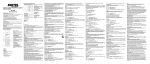
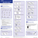
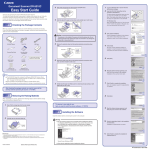
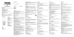
INGOS Ltd.
AUTOMATIC AMINO ACID
ANALYSER
AAA 400
User manual
PRAGUE
Apr 11 2006
Producer
:
Laboratory Instruments division of INGOS Ltd.
Development
Chemical system
:
:
PiKRON Ltd.
V. Havlíček - ZMBD chemik
Supplier and service
:
INGOS Ltd.
K Nouzovu 2090
14316 PRAGUE 4
CZECH REP.
(c) INGOS 2006
Tel: +420 296 781 683
+420 296 781 692
Fax: +420 244 403 051
e-mail:[email protected]
TECHNICAL CHARACTERISTICS
GETTING STARTED WITH THE ANALYSER
PUTTING INTO OPERATION
ROUTINE MAINTENANCE AND SERVICING
ACCESSORIES AND SPARE PARTS
INDEX
TABLE OF CONTENTS
1
2
3
4
5
6
7
1. TECHNICAL CHARACTERISTICS
Amino acid analyser is a special compact liquid chromatograph designed for the
analysis of amino acids on a ion exchanger column with a post-column derivatisation by
means of ninhydrin and for the determination of biogenic amines.
1.1 Parameters
Sensitivity . . . . . . . . . . . . . . . . . . . . . . . . . . . . . . . . . . . . . . . . 50 pmol
Reproducibility at 10 nmol . . . . . . . . . . . . . . . . . . . . . . . . better than 1.5 %
Glass column, dimension . . . . . . . . . . . . . . . . . . . . . . . . . . 0.37 x 45 cm
Heating within the range . . . . . . . . . . . . . . . . . . . . . . . 35 to 95 0 C
Filling for the id. of hydrolysates . . . . . . . . . . . . . . . . Ostion Lg ANB
Filling for the id. of free AA . . . . . . . . . . . . . . . . . . . . Ostion Lg FA
Pumping system . . . . . . . . . . . . . . . . . . . . . . . . . . . . . . . . . . Derived from LCP5020
Flow rate . . . . . . . . . . . . . . . . . . . . . . . . . . . . . . . . . . . . . . . 0.01 to 10 ml/min
Pressure . . . . . . . . . . . . . . . . . . . . . . . . . . . . . . . . . . . . . . . . 0 to 20 MPa
Automatic dispenser with the cooling of samples
No. of samples with the cassette A . . . . . . . . . . . . . . 25 x 1.5 ml
No. of samples with the cassette B . . . . . . . . . . . . . . 40 x 0.5 ml
Two-channel detector . . . . . . . . . . . . . . . . . . . . . . . . . . . . . .440 and 570 nm
Cell volume . . . . . . . . . . . . . . . . . . . . . . . . . . . . . . . . . . . . 5 µl
Reactor . . . . . . . . . . . . . . . . . . . . . . . . . . . . . . . . . . . . . . . . . . . 50 to 150 0 C
Processing and print of results . . . . . . . . . . . . . . . . . . . . . PC with program Chromulan
Communication with PC . . . . . . . . . . . . . . . . . . . . . . . . . . RS485
Power supply . . . . . . . . . . . . . . . . . . . . . . . . . . . . . . . . . . . . . . 230 V, 10%, 50 Hz
Power input . . . . . . . . . . . . . . . . . . . . . . . . . . . . . . . . . . . . . . . 230 V x 1.6 A
Category of over-voltage within installations . . . . . . . II.
Dimensions w x h x d . . . . . . . . . . . . . . . . . . . . . . . . . . . . . 700 x 600 x 550
Weight without bottles . . . . . . . . . . . . . . . . . . . . . . . . . . . . 55 kg
1.2 Environment
The apparatus is designed for the environment with a temperature of 15 to 30 0 C;
humidity up to 80 % without any acid and caustic vapours. For the reasons of ventilation
a free area of 0.15 must be available behind the apparatus.
1.3 Operation
During operation it is necessary that side covers be fitted, column door be closed and
waste systems be correctly connected (2.3.1).
1.4 Handling
The apparatus can be carried manually by two persons who grasp it with two hands
at the bottom part of side frames.
INGOS s.r.o.
Page 4
1
AAA 400
Section 1: TECHNICAL CHARACTERISTICS
1.5 Analytic cycle control
Analytic cycle control and processing of results require the connection of a PC equipped with the program Chromulan.
The program Chromulan contains a help facility designed for the selection and preparation of all operational solutions. Programs for the basic types of analyses, including
all settings are delivered together with the program.
1.6 Chemicals
On the basis of an order it is possible to deliver chemicals for the production of
operational solutions, but it is not a precondition for the operating of AAA400.
The apparatus is equipped with a chemical part of the operating instructions which is
designed for the work with chemicals and compilation of analytical programs and contains
the description of all issues relating to the chemical properties, sample preparation and
tuning of the analytical cycle.
1.7 Safety
The amino acid and biogenic amines analyser cannot be used in any way other than
those provided for in the operating instructions in order not to violate safety regulations.
INGOS s.r.o.
Page 5
1
2. GETTING STARTED WITH THE ANALYSER
2
2
1
3
6
11
4
10
9
12
8
7
13
5
1.
2.
3.
4.
Buffers
Ninhydrin
Dispenser disk
Valves for the switching of NHD/
H2 O
5. Valves for the switching of the buffers
6. Ninhydrin pump 2
7.
8.
9.
10.
11.
12.
13.
Buffer pump 1
Air release valve for ninhydrin
Air release valve for buffers
Pre-column
Column
Reactor
Detector
Fig. 1. Layout of individual parts of AAA 400
The area under the upper cover serves for the placement of bottles with buffers, distilled water (H2 O) and cooled bottles with the reagent (ninhydrin, hereinafter referred
to as NHD). This area also contains a dispensing system with a stock of cooled samples.
The front part of the apparatus contains in its lower left part a panel fitted with electromagnetic valves which choose one of six buffers for Pump 1 (buffer type) situated in the
lower part and also switch H2 O and NHD for Pump 2 situated in the upper part.
The air release valves are situated on the panel between the pumps, Pump 1 valve
being on the right and Pump 2 valve being on the left.
The air release valves situated behind the panel contain tensometric pressure sensors.
The middle area of the lower part of the apparatus contains a door with a keyboard
and a display. The area behind the door contains a reactor with a replaceable cartridge
and a detector with a through-flow cell.
INGOS s.r.o.
Page 6
AAA 400
Section 2: GETTING STARTED WITH THE ANALYSER
The right front part of the apparatus contains, behind the transparent door, a column
designed for the separation of amino acids. The column is gripped by a metal bed which
heats it. The cooling of the bed with the column is carried out by a fan located in the
upper part of the area with the column.
Side panels of the apparatus are easily removable and thereby you can get access to
most mechanisms and electronic equipment.
The left side of the apparatus is fitted with the main switch. After removal of the left
side panel you will get access to the fuses of the power supply of both the network inlet
and for individual modules of the apparatus.
In order to clarify the function, design and layout of the individual units of the
apparatus, the entire apparatus is, for the purpose of further description, divided into
the following parts:
Power supply and fuses
Pumps
Hydraulic system
Dispensing system
Columns
Detector with reactor.
Key board
2.1 Power supply and fuses
Power supply is situated in a closed box. All outlet connectors and terminals transfer
only safe voltages. The source contains a special fuse for each unit, see fig. 2.
1. Fuses of individual units. The value of the fuse
is provided for on the description card next to
the fuse.
2. Connectors for the power supply of individual
units. All connectors feature a voltage of 24V.
1
2
Fig. 2. Power supply - Fuses and outlet connectors
INGOS s.r.o.
Page 7
2
AAA 400
Section 2: GETTING STARTED WITH THE ANALYSER
The source contains a transformer for the heating of the column 7 V AC and two
switched sources which separate the mains voltage of 230 V AC from the voltage of individual modules of the apparatus through a safety voltage of 24 V DC. In the STANDBY
mode only one source designed for the power supply of the cooling system and keyboard
is operating.
2.1.1 Mains connection
The mains connection is situated on the rear panel of the apparatus. Also the main
fuse (value T2.5A) is situated on the same place.
2.1.2 Secondary mains fuses
After removal of the left panel you will see secondary mains fuses, see fig. 3. T0.63A
with the description COLUMN. T1.6A for the mode STANDBY and T1.6A OPERATION
for the operation of other units of the analyser.
1.
2.
3.
4.
2
3
Power switch
Fuse of the column heating system
Fuse of the operation mode
Fuse of the Standby mode
1
4
Fig. 3. Power supply - Switch and fuses
2.1.3 Front panel of the source
The front panel of the source contains connectors designed for the power supply of the
modules of the apparatus, its signalling lamps and fuses. The assignment and values of
the fuses are given by the description. PUMP 1 T2.5A, PUMP 2 T2.5A, VALVES T0.5A,
SAMPLER T2.5A, DETECTOR T3.15A, RESERVED T2.5A, KEYBOARD T0.5A, COOLING T6.3A.
2.1.4 Fuses in the switched sources
Besides the above specified fuses the apparatus contains inaccessible fuses situated in
the switched sources. Each source has one fuse F4A.
2.1.5 Power supply control
Through the DIN7 connector the apparatus receives a repeated command for operation (OPERATION) and a regulation command of heating of the column for the switching of the 230 V AC transformer whose outlet terminals (7 V, 11 A) are also situated
on the front panel of the source.
2.2 Pumps
The pumps are pulse-free and feature an even power output and their use guarantees
conformity of the retention times of individual peaks. The software equipment controlling
INGOS s.r.o.
Page 8
2
AAA 400
Section 2: GETTING STARTED WITH THE ANALYSER
the units of the pumps during the switching ON of the analyser will set the pressure limit
of pump 1 to 8 MPa and pump 2 to 3 MPa. The maximum pressure permitted for the
analyser is 20 MPa. The upper pressure limit will be set after the activation of the
program Chromulan 2 MPa above the level specified in the program.
The pumps feature the flush of the piston behind a high-pressure gland. This makes
it possible to pump crystallising substances (buffers) without the glands and pistons
being damaged. The flush is ensured by the second section of the peristaltic pump (2.4).
PUMP 1 permits the pumping at a maximum flow rate of 10 ml/min. PUMP 2 features
a half stroke of the pistons in order to ensure a perfect function during the pumping of
NHD, and therefore the real maximum flow rate is 5 ml/min.
2
1
1
2
3
3
4
4
5
5
6
6
1. Inspection windows where it is possible
to see movement of the pistons
2. Piston flush inlets
3. Output valves
4. Heads
5. Piston flush outlets
6. Input valves
Fig. 4. Pumping block
2.3 Hydraulic system
Hydraulic system is formed by bottles for 6 buffers, a bottle for H2 O and a cooled
bottle with NHD. All liquids are conducted from the bottles to electromagnetic valves
situated in the lower left part of the analyser. Hoses leading from individual buffers are
conducted to them. These hoses bear colour marking at the outlet of the hoses to the panel
above the valves. They are factory-set in an order from the left to the right. The buffer no.
1 hose is situated on the left, the last hose belongs to the buffer no. 6. Then the system
continues with NHD and H2 O. H2 O is used also for the flushing of the dispensing valve
and dispenser needle by the first section of the peristaltic pump and for the flushing of
pump pistons by means of circulation through the second section of the peristaltic pump.
2.3.1 Waste
Waste originating from the rinsing of the dispensing system, condensed water from
cooling samples and NHD are conducted to a single outlet situated on the rear part of
the apparatus, which is connected to the waste canister.
The outlet of the buffers consumed and NHD is conducted out from the cell by means
of a capillary tube featuring a clearance of 0.3 mm up to the waste canister.
INGOS s.r.o.
Page 9
2
AAA 400
Section 2: GETTING STARTED WITH THE ANALYSER
2.3.2 NHD
The bottle with NHD is situated in the metal pit which is cooled by means of thermoelectric cooling modules.
2.4 Dispensing system
For the dispensing system see fig. 5. The system consists of a removable disk designed
for 25 or 40 micro test tubes closed with plugs, an arm with a needle, loop dispensing
valve, optical sensors of the through-flow of the liquid through a hose (sensor 1 and
sensor 2) and peristaltic pump. The disk fitted with the micro test tubes is stored in a
cooled metal ring and thus the stability of samples is ensured for a long time.
7
6
5
1.
2.
3.
4.
5.
6.
7.
Arm with needle
Peristaltic pump
Dispensing disk
Micro test tube with a sample
Loop dispensing valve
The first sensor of the liquid
The second sensor of the liquid
1
2
3
4
Fig. 5. Dispenser
The system is controlled by its own microprocessor, which performs the commands of
the control computer. The computer issues commands for the preparation of a nominal
sample and a command for the start of the analysis.
During preparation the peristaltic pump flushes the dispensing valve, hose and needle
with distilled water. By applying the reverse procedure it dries all with air.
The disk brings the micro test tube selected to the arm. The arm rotates and pricks
the micro test tube plug through with a needle.
The filling of the dispensing loop is controlled by optical sensors which recognise
whether there is a liquid or air in the hose passing through the sensor.
The peristaltic pump draws a sample behind Sensor 1, the needle leaves the micro test
tube and by means of the rotating of the arm it returns to its position above the waste.
INGOS s.r.o.
Page 10
2
AAA 400
Section 2: GETTING STARTED WITH THE ANALYSER
The peristaltic pump finishes pumping the sample through the loop of the dispensing
valve to Sensor 2.
At the moment of the start of the analysis the dispensing valve turns from the LOAD
position to the INJECT position. After a certain time the valve returns back.
The peristaltic pump will flush the loop of the dispensing valve and the H2 O needle.
2.5 Columns
There are two columns at this type of the apparatus. Pre-column and analytic column.
The pre-column is made of Plexiglas and its lower and upper closures are the same.
1
2
1.
2.
3.
4.
5.
Cooling fan of the column
Upper closure of the column
Column
Heating of the column
Lower closure of the column
3
4
5
Fig. 6. Column
The pre-column can be operated from both directions. The pre-column serves for the
absorption of ammonia which gets to the column from acid buffers. This ammonia is
washed out by means of alkaline buffers featuring a higher ionic strength and cancels the
identification of arginine. For the purpose of accelerated identifications where no arginine
INGOS s.r.o.
Page 11
2
AAA 400
Section 2: GETTING STARTED WITH THE ANALYSER
assessment is carried out this pre-column is not necessary. The analytical column is of a
glass type with plastic stands serving for the attachment of closures. The upper closure
makes it possible to shorten the active length of the column. The pre-column is situated
in the holder behind the keyboard. The analytical column is situated in the heating metal
bed which ensures a controlled temperature mode for the column.
CAUTION: The door of the column must be closed during the operation.
2.6 Detector with reactor
Detector with reactor are, together with the control unit, situated on the removable
plate behind the keyboard.
2.6.1 Reactor
The reactor consists of a box fitted with a heating element and removable cartridge
with an embedded Teflon pipe. The cartridge is held in the heating body by means of a
bayonet closure.
2.6.2 cell
The detector cell is attached between the detector body and halogen lamp cooler,
see fig. 7. The light which passed through the cell is, after a reflection from the concave
holographic grillage, read by the photocells placed on the positions of 440 nm and 570
nm.
1
4
5
2
6
3
1.
2.
3.
4.
Detector
Cell
Liquid line from the reactor to the cell
Halogen lamp
5. Drainage of liquid from the cell to the
waste system
6. Lamp cooler
Fig. 7. Cell attachment
INGOS s.r.o.
Page 12
2
AAA 400
Section 2: GETTING STARTED WITH THE ANALYSER
The lamp is calibrated in the mop board by the manufacturer in factory and in the
case of replacement it does not require, apart from the inserting and screwing into the
cooler, any adjustment. Be careful to handle with the pin.
The capillary tube from the column is connected to a T-union attached in a removable
way in the plastic bed attached in front of the reactor. Also the capillary tube leading
from the pump 2 (NHD, H2 O) is connected to this union.
One end of the capillary tube from the rector cartridge is connected at the outlet of
the T-union. The other end of this capillary tube is connected to the detector cell.
CAUTION: The cell must be attached in such a way that the inlet from the reactor
heads obliquely downwards, to the detector body, see fig. 7
2.6.3 Outlet from the cell
The outlet from the cell is realised through a capillary tube, whose length is at least
3 m, of a clearance 0.3 mm, and it is recommended to conduct this capillary tube up to
the waste canister.
2.7 Keyboard
The apparatus is fitted with a keyboard and a display. The keyboard serves for
the control of all units during debugging, servicing and controlling AAA400. It is also
convenient during the flooding of the hydraulic system. From the keyboard it is possible
to receive all current information about the modules of the apparatus.
1
2
4
"!$#% &''
MAIN
MENU
PROG
F1
F2
F3
F4
F5
ESC
INSERT
LINE
DFELETE
LINE
RUN
END
PUMP
1
PUMP
2
SAMPLER
DETEC
TEMPER
VLAVES STANDBY
HELP
7
8
9
4
5
6
1
2
3
0
5
ENTER
3
1. Display
2. Function keys
3. Keys for switching between displays
4. Cursor keys
5. Numeric keys for the entering of numeric data
Fig. 8. Keyboard
Individual modules of the apparatus can be inspected and possibly also controlled
from this keyboard. On the activation of the program Chromulan all the default values
pre-set by the manufacturer or by the operators from the keyboard will be overwritten
by the values entered into a particular program by the author of the analytical program.
2.7.1 Switching on of the apparatus
INGOS s.r.o.
Page 13
2
AAA 400
Section 2: GETTING STARTED WITH THE ANALYSER
The keyboard provides information concerning the switching ON of the apparatus
and the putting aside to a STANDBY mode, which is indicated by the yellow signalling
lamp of the key.
If the apparatus is activated from the STANDBY mode by means of pressing this key
or through a computer program Chromulan, it is possible to get access to individual modules by pressing the keys PUMP 1 PUMP 2 SAMPLER DETEC TEMPER VALVES
By pressing each of the above mentioned keys the display will provide the information
concerning the module selected by the key in question. If the module is active, the corresponding LED on the keyboard is lit. The emergency condition is indicated by the flashing
of this LED. A failure in the module can generally be reset by using the command Off
F5 . It is necessary to remove the cause and to activate the unit in question again.
If you want to select another value, it is necessary to move cursor to the position of
the number to be changed (it is done by horizontal arrows of the keyboard). After entering
the number you must confirm it by pressing ENTER, should you make a mistake, you
can delete the number edited by pressing the key ESC.
The area below the bottom line of the display contains the keys F1 F2 F3 F4 F5 .
The meaning of these keys is given by the bottom line of the display activated for the
module selected by the key.
2.7.2 Pumps PUMP 1, PUMP 2
With the key PUMP 1 (PUMP 2) it is possible to open the display of the pump 1
(2).
Pump 1 On
FLOW P-H P-L P MPa
0.30 12 0.0
4.5
=== === Purg On Off
From the display you can see:
On
(Purge, Error, Off ) - immediate state of the pump.
Flow
pre-set flow rate (usually 0.30 and 0.20 ml/min).
P-H
emergency pressure limit (factory set as 8 MPa for PUMP 1 and 3 MPa for
PUMP 2).
P-L
lower pressure limit (usually 0 MPa).
P MPa current pressure.
The meaning of the function keys is as follows::
F3 Purge
The pump is pumping at a rate of 8 ml/min and possible exceeding of
the pressure limit 1 MPa is checked.
F4 On
Starts pumping at a flow rate given under Flow.
F5 O
Stops pumping or possibly resets after an error indicated by the flashing
of the corresponding LED.
2.7.3 Dispensing system SAMPLER
INGOS s.r.o.
Page 14
2
AAA 400
Section 2: GETTING STARTED WITH THE ANALYSER
Through the key SAMPLER it is possible to open the display of the dispensing
system.
Sampler Off
Number
1
Cal Pre Load Man Off
2
From the display it is possible to see:
ḃf Off
(On, Error, Prepare ) - immediate state of the dispenser.
Number The number of the sample which has been dispensed most recently.
The meaning of the function keys is as follows:
F1 CAL
Performs the flooding of the dispensing valve, needle and calibration of
sensors of the liquid in the hoses of the dispensing system. (This function
is performed automatically at a transfer from the STANDBY mode and
during the activation by the program Chromulan.
F2 PRE
Takes a sample from the test tube selected, (XX + ENTER). Preparation
for dispensing.
F3 LOAD
Dispenses a sample into the system, the sample must be prepared by
using the key PRE (F2), or, if the function PRE has not been used in
advance, it will perform both preparation and dispensing.
F4 MAN
Turns the dispensing valve. The valve must be returned into its position
by repeating MAN (F4).
F5 OFF
Mainly for resetting after an error. (The LED is flashing).
Note: The LED SAMPLER is lit during the time of preparation of the dispensing
and flushing up to the complete end of the dispensing sequence.
2.7.4 Detector DETEC
The display is listing current absorbance values for the green channel (Green 570 nm)
and blue (Blue 440 nm).
Detector On
Green
Blue
0.0621 0.0163
=== FIC Zer On
Off
From the display you can see:
On
(Off, Error) - immediate state of the detector.
Green
Absorbance for the green channel.
Blue
Absorbance for the blue channel.
The meaning of the function keys is as follows:
F4 On
Turns the lamp ON.
INGOS s.r.o.
Page 15
AAA 400
F5 O
F2 FIC
F3 Zer
Section 2: GETTING STARTED WITH THE ANALYSER
Turns the lamp OFF, resets an error.
Performs the basic calibration of the electronic installations of the detector. It is carried out automatically every time when turned on.
Resets both channels.
2.7.5 Electromagnetic valves VALVES
Valves
Buff Reagen
1
NHD
=== === ==== NHD H2O
From the display it is possible to see:
Bu
Number of the buffer valve which is open. Zero means that all valves are
closed.
Reagen NHD/H2O identification of the valve which is open.
The meaning of the function keys is as follows:
F4 NHD
Opens the valve for ninhydrin.
F5 H2O
Opens the valve for water.
The number of the buffer can be selected, the selection shall be confirmed by the key
ENTER. By selecting the non-connected valve 7 or 8 the display shows 0 and all buffer
valves are closed.
2.7.6 Thermostat of the column and reactor TEMPER
Through the key TEMPER you will open the display with information on the temperatures of the column and reactor.
Column Reactor
Act 60.1
109.9
Fin 60.0 " 110.0 "
=== On Off On Off
From the display you can see:
Act
Current temperatures of the column and reactor.
Fin
Required temperatures of the column and reactor.
This sign behind the temperature required means that the heating is switched
on.
The meaning of the function keys is as follows:
F2 On
Switches the heating of the column ON.
F3 O
Switches the heating of the column OFF.
F4 On
Switches the heating of the reactor ON.
F5 O
Switches the heating of the reactor OFF.
INGOS s.r.o.
Page 16
2
AAA 400
Section 2: GETTING STARTED WITH THE ANALYSER
In the case that at least one regulation is ON, the LED of the key TEMPER is lit.
2
INGOS s.r.o.
Page 17
3. PUTTING INTO OPERATION
It is presupposed that the operators have been made familiar with analytical issues
and with the use of the program Chromulan.
The apparatus can only work without any surveillance if it is controlled by a computer
equipped with the program Chromulan. This program perfectly protects the column from
pressure overloads, it is able to detect any leakage of liquid on the basis of pressure loss.
Thus it ensures safety of operation of the electric equipment containing thermostats,
pumps and chemical solutions. All operational parameters must be present within the
ranges specified by the program. In the opposite case the apparatus is put into the
STANDBY mode.
3.1 Apparatus preparation
3.1.1 Electric connection
The apparatus is connected to the power supply with a mains cord, and with the
communication cable it is connected to a computer fitted with the communication card
RS485.
3.1.2 Waste
The waste systems are connected from the cell and dispensing system, see Chapter
2.3.1 page 9 .
3.1.3 Chemicals
The bottles contain a sufficient stock of buffers, distilled water and NHD. A hose with
protective atmosphere is connected to the NHD bottle.
3.2 Turning the apparatus ON
Important notice. If the apparatus has just been put into the STANDBY mode, the
yellow LED must be lit before the repeated turning ON for at least 10 sec. The apparatus
cannot be turned ON earlier from the computer or the key STANDBY.
3.2.1 Switch
The ready apparatus will be turned ON with the switch on the left side of the apparatus. The button of the switch and the LED STANDBY will be lit. In this state only
the cooling of NHD and samples is turned ON. It is recommended that this switch should
not be turned OFF at all for the time while there is some NHD in the reservoir.
3.2.2 Actual turning ON
The actual turning ON can conveniently be performed by the controlling computer.
The computer is fitted with a monitor, and if you want to print results during the work
of the analyser, it is also fitted with a printer connected in advance with the cable
CENTRONIC to the computer. (The power supply of the printer need not be turned
ON).
INGOS s.r.o.
Page 18
3
AAA 400
Section 3: PUTTING INTO OPERATION
An advantage of the activation of the analyser by using the program Chromulan is
the control of the pump 2 depending on the pump 1. Pump 1 only starts pumping after
the heating of the column to a temperature pre-set by the program, and pump 2 must
always feature a pressure smaller than the pressure of pump 1. Another precondition
for the activation of the pump 2 is the reactor temperature higher than 70 o C. If the
apparatus is not ready within 30 minutes (for example the pumps are not flooded), the
program starts indicating an emergency condition. The operators can take over, for a
certain period of time, the responsibility for the values situated out of the range limits
by entering the command F9 and for the emergencies by confirming during the message
PUT ASIDE - EMERGENCY Y/N by entering N. During the time of the apparatus
preparation the reporting of the conditions out of range and of emergencies is limited
to a minimum, and it is also suitable to monitor the running-in of the apparatus. It is
recommended to be in an area where you can hear alarms for the time of identification
of the first sample.
Also the apparatus which is not controlled by computer can be activated by pressing
STANDBY. The values are set in the controlling units of the modules in such a way that
the apparatus shall not be damaged.
3.3 Turning the apparatus OFF
The apparatus will be turned OFF by the computer after the processing of all samples.
It will be followed by the flushing of the reactor by stopping the pump 2 and after a certain
time it will start turning individual modules of the apparatus OFF and at the end the
apparatus will pass to the STANDBY mode. In this mode also electromagnetic valves are
turned OFF and the column is not endangered by NHD.
3.3.1 Turning OFF due to an error
If the computer stops communicating with the apparatus for the time of one minute,
the apparatus starts preparing itself for the passage to the STANDBY mode. It will
switch electromagnetic valves of the pump 2 to H2 O and starts to turn OFF individual
modules of the apparatus on a sequential basis.
3.3.2 Turning OFF by operators
Termination of operation may be decided about by the operators pressing the key
STANDBY and thus the apparatus will immediately be put aside.
3.4 Inserting of samples into the dispensing disk
It is carried out by removing the disk for the micro test tube. First slide the ring
on the centre of the disk upwards and while pulling this ring, remove the disk from its
installation.
Remove old micro test tubes and insert the new ones.
Put the disk on the carrier in such a way that it can latch as low as possible with its
pivots into the five holes of the carrier. Slide the ring with the groove evenly downwards
and thereby attach the disk into the carrier.
INGOS s.r.o.
Page 19
3
AAA 400
Section 3: PUTTING INTO OPERATION
3.5 Flooding of the liquid inlets towards the pumps
During the first start-up or after the connection of hydraulic paths it is necessary to
monitor the tightness of all hydraulic joints and parts. Most leakage will be indicated by
liquid drops collected in the tray under the pumps. Furthermore it is necessary to monitor
the connection of the cell, reactor, dispensing valve and upper closure of the column. All
leakage on the column will be revealed on its lower end and on the hose from the bottom
closure of the column.
3.5.1 Bleeding
Bleeding is carried out by opening the corresponding air release valve and increasing
the pumping rate subsequently, exclusively through the command Purge F3 . After the
entering of this command the pump starts pumping much faster (8 ml/min). An advantage
of the function Purge is that it controls the value of the pressure, and if the air release
valve is not open it will stop the pump at a pressure of 1 MPa and in the upper line of
the display it will write Error. Each Error must be reset by the command OFF F5.
3.5.2 First ooding
If the pump has not been flooded yet , it is necessary to proceed as follows:
Turn the apparatus ON, see 2.7.1 page 13
Open the air release valve of the pump 1.
By using the keys VALVES 1 ENTER open the valve of the buffer 1.
By using the keys PUMP 1 F3 start the pumping of the pump 1 at a higher rate
(function purge). If the pump fails to draw the buffer by itself, it is suitable to flood the
pump with the help of the connection of a syringe to the waste pipe of the air release
valve by using a thick-wall hose and syringe suction.
Other buffers will be drawn by the pump probably without a help of this kind. It is
sufficient to switch between individual buffers 2, 3, 4, 5 and 6 at the VALVES mode.
The flooding will be terminated by the command OFF or ON. After the closing of
the air release valve it is possible to check the oscillation of pressure on the display or
computer and to find out the quality of the bleeding.
The same procedure will be applied to the bleeding of the second pump. PUMP 2,
VALVES, NHD, H2 O.
3.5.3 Irregular pumping
If the pump pumps irregularly, it is possible to take over the keyboard control and
carry out the bleeding.
At the time of preparation it is possible to check also all buffers. Open the display by
using the key VALVES and then it will be possible to switch between individual buffers
by using the numbers 1 to 6 + the key ENTER, or by using the keys F4 and F5 it is
possible to transfer H2 O or NHD into the pump 2.
3.6 Starting of analysis
The actual starting of the analysis of the samples prepared will be carried out by
means of computer. It will start with the running- in part of the analytical cycle and
INGOS s.r.o.
Page 20
3
AAA 400
Section 3: PUTTING INTO OPERATION
then it will be followed by the analysis of the first sample. More information can be
found in user manual for Chromulan
3
INGOS s.r.o.
Page 21
4. ROUTINE MAINTENANCE AND SERVICING
4.1 Regular maintenance
Perform the filling of operational solutions and check all joints for tightness in regular intervals. The preparation of buffers and ninhydrin is carried out according to the
instructions which are available in the program Chromulan and in the independent part
of the instructions focused on chemistry. Since the solutions are chemical substances of
various categories, it is necessary to observe safety regulations.
4.1.1 Safety regulations for the work with Na buers
These regulations concern the compounds of citric acid and sodium chloride, which
are the ingredients commonly contained in foodstuffs and therefore it is not necessary to
observe any special safety regulations.
4.1.2 Safety regulations for the work with Li buers
These buffers are similar to Na buffers but they are more aggressive against metals.
It is not necessary to observe any special safety regulations for these buffers either.
4.1.3 Safety regulations for the work with NHD
Use always rubber gloves while working on the preparation of the agent. If your skin
gets into contact with this substance, wash the contaminated place with water and pour
sodium pyrosulphite on it. If you find blue stains on the skin, pour sodium pyrosulphite
on them as well and wash them with lukewarm water. In the case of consumption try to
induce vomiting and immediately call for medical aid.
4.1.4 Bottling of operation liquids
The pouring of operation liquids into bottles shall be carried out from the apparatus
area, and only properly dried bottles can be put into the apparatus. If you spill the
solution onto the apparatus, wipe it as soon as possible with cellulose wadding.
4.1.5 Check for tightness
During the start-up, during the time of the first analysis and if you intend to leave
the apparatus in operation for a longer time (night, weekend) it is necessary to carry out
visual checks for tightness of all joints and parts through which the liquid flows. Check
the tray situated in the front part of the apparatus, connection of the reactor and detector
cell, dispensing valve and the column. Any leakage of the column will be revealed on its
lower end.
4.1.6 Check of waste
Perform daily checks of the waste canister and pour its content to the sewerage system
in time.
4.2 Parts which are subject to wear
INGOS s.r.o.
Page 22
4
AAA 400
Section 4: ROUTINE MAINTENANCE AND SERVICING
This subsection concerns the parts which are subject to wear depending on the load
and/or time.
4.2.1 Electromagnetic valve hoses
If a hose is worn due to a permanent compression, it is possible to restore it for a
shorter time by sliding it gently within the spring collet of the valve. It is appropriate to
replace hoses of all valves after one year of operation. Put the obliquely cut hose with
its oblique side through the collet of the electrically opened valve, see 1.75, pull it out
with tweezers and cut it evenly on both ends for the length required. Slide it on the
corresponding metal couplings.
4.2.2 Peristaltic pump hoses
These hoses are loaded by pumping and still more by tensioning across the pump head
assembly, also when the pump does not work. The spare part kit contains also complete
hoses. It is possible to prepare other hoses by using the basic material and their design.
The length of a silicone hose (clearance 1mm, wall thickness 0.5mm) is 80 mm. Practical
lifetime is about 2 months. We recommend you to replace both hoses at the same time.
Thus it is possible to ensure reliable flushing of pistons of the main pumps and thus also
a good lifetime of the most important parts of the analyser.
4.2.3 detector lamp
It is a halogen lamp attached in the metal holder. It is attached by means of two
screws M3 and connected with terminals to the power supply system. The voltage on the
terminals is 5 V DC. The lifetime is approximately 2000 hours and generally the lamp
works without any problems for its entire lifetime. After the replacement no adjustment
is made. The fact that the lamp is lit can be seen when looking behind the keyboard of
the apparatus.
4.3 Error message printout
If the analyser is switched OFF by the program Chromulan for other reasons than
the processing of all samples, the information panel of the program called up by F9will
remain in the condition for which the apparatus has been put aside. It is possible to read
temperatures, pressures and to find the error message. On the sequence screen F4the line
which was not performed flashes red. If you move cursor to this line and press ENTERthe
corresponding error message will be displayed. The numbers displayed can be conveniently
recorded for the analysis of the failure and for possible agreement with the service station.
4.3.1 General information about the state of the dispenser
0
1
2
3
4
5
Dispenser is in the basic position
Sample is ready in the loop
Dispenser is operating
It is not possible to set the sensitivity of the sensors
Error of sensor 1 or no sample
Error of sensor 2 or a bubble
INGOS s.r.o.
Page 23
4
AAA 400
6
7
8
9
10
Error
Error
Error
Error
Error
Section 4: ROUTINE MAINTENANCE AND SERVICING
in
in
in
in
in
the dispensing sequence
the arm motor
the peristaltic system motor
some of the DC motors
the positioning of the disk
4.3.2 Status information from the dispenser
State Error Description
0
Standby mode
Preparation of dispensing
1
-767
close the valve, check the arm
2
-766
wait for the pulling out of the arm, then cleaning
3
-765
wait for water in both sensors, then volume flushing
4
-764
flushing with a certain volume, then air separation
5
-763
wait for air in sensors, then fixed volume of air
6
-762
drawing of a fixed volume of air
7
-761
reserve
Beginning of the actual dispensing sequence
8
-760
waiting for the disk, then start of the arm downwards
9
-759
waiting for the arm and beginning of suction
10
-631
suction into sensor 1, then suction of a certain volume
11
-757
completion of the volume suction, then the arm upwards
12
-756
travel of the arm upwards, then suction into sensor 2
13
-630
suction into sensor 2, then time synchronisation
14
-754
suction of a sample, slightly behind sensor 2
Waiting for the command inject
15
-639
time synchronisation, then dispenser to INJECT
16
-752
completion of the dispenser movement to INJECT
17
-751
waiting for a certain time, then dispenser to LOAD
18
-750
dispenser to LOAD, then flushing of the loop
19
-749
flushing of the loop, then end or calibration
20
-748
reserve
Calibration of sensors
21
-747
beginning of calibration - reserve
22
-746
beginning of the flushing of the peristaltic system
23
-745
peristaltic system is flushing, then preparation of the
calibration of sensors
24
-744
calibration of sensors for water, then drying
25
-743
drying
26
-742
drying by peristaltic system, then air calibration
27
-632
air calibration, then filling with water
28
-740
completion of the filling with water
INGOS s.r.o.
4
Page 24
AAA 400
Section 4: ROUTINE MAINTENANCE AND SERVICING
4.4 Waste disposal
When the instruments operating life is over dispose it in respect to valid regulations,
also it can be returned to the vendor or producer for liquidation.
Warning: Instrument contains parts (PCB’s) which are rated as hazardous waste.
4
INGOS s.r.o.
Page 25
5. ACCESSORIES AND SPARE PARTS
5.1 Basic accessories
90000026
Ion exchanger for column LG FA (free a.a., biogenic amines)∗
90000027
Ion exchanger for column LG ANB (hydrolyzát)∗ . . . . .
90000025
Ion exchanger for precolumn LG 0804 . . . . . . . . . .
AA 4500
Empty column with caps
. . . . . . . . . . . . . . .
AA 4529
Spacer tube 60 mm . . . . . . . . . . . . . . . . . .
AA 4528
Spacer tube 30 mm . . . . . . . . . . . . . . . . . .
AA 4621
Column filler cap, capillary, threaded joint and sealing
. .
90000028
Syringe with tubing for column filing
. . . . . . . . . .
AA 4611
Precolumn tube
. . . . . . . . . . . . . . . . . . .
AA 4631
Precolumn filler cap with sealing . . . . . . . . . . . .
AA 1781
UNF10 through bolt, PEEK . . . . . . . . . . . . . .
AA 1782
UNF10 flow-cell through bolt, PEEK . . . . . . . . . .
AA 1783
UNF10 through bolt, stainless steel . . . . . . . . . . .
AA 1784
UNF10 long through bolt, stainless steel . . . . . . . . .
AA 1785
Ferrule, stainless steel . . . . . . . . . . . . . . . . .
AA 1787
PEEK coupler . . . . . . . . . . . . . . . . . . . .
5KAP0006 PTFE capillary O.D. 1.6mm, I.D. 0.3mm
. . . . . . . .
5KAP0007 PTFE capillary O.D. 1.6mm, I.D. 0.8mm
. . . . . . . .
5HAD0004 Silicon tubing O.D. 5mm
. . . . . . . . . . . . . . .
5HAD0002 Silicon tubing O.D. 3mm
. . . . . . . . . . . . . . .
5HAD0003 Polyamide waste tubing . . . . . . . . . . . . . . . .
AA 2520
Peristaltic pump loop . . . . . . . . . . . . . . . . .
AA 2170
Mounting device for peristaltic pump loop . . . . . . . .
AA 2140
Sampler needle . . . . . . . . . . . . . . . . . . . .
AA 4250
Tungsten lamp . . . . . . . . . . . . . . . . . . . .
5SKL0032 Bottle set . . . . . . . . . . . . . . . . . . . . . .
AA 5203
Eppendorf vial 1.5 ml . . . . . . . . . . . . . . . . .
3VOD0003 Feed cable . . . . . . . . . . . . . . . . . . . . . .
Comunication cabel . . . . . . . . . . . . . . . . . .
Fuse T 1 A
. . . . . . . . . . . . . . . . . . . . .
Fuse T 1.6 A
. . . . . . . . . . . . . . . . . . . .
Fuse T 2.5 A
. . . . . . . . . . . . . . . . . . . .
Fuse T 3.15 A . . . . . . . . . . . . . . . . . . . .
Fuse T 6.3 A
. . . . . . . . . . . . . . . . . . . .
90000034
Spanner number 7mm
. . . . . . . . . . . . . . . .
Spare vial 20ml
. . . . . . . . . . . . . . . . . . .
∗
Depends on specified usage
INGOS s.r.o.
.
.
.
.
.
.
.
.
.
.
.
.
.
.
.
.
.
.
.
.
.
.
.
.
.
.
.
.
.
.
.
.
.
.
.
. . 20ml
. . 20ml
. . 20ml
. . 2 pcs
. . 4 pcs
. . 2 pcs
. . 1 pc
. . 1 pc
. . 1 pc
. . 1 pc
. 10 pcs
. . 2 pcs
. . 3 pcs
. . 1 pc
. . 4 pcs
. . 1 pc
. . 6m
. . 1m
. 0.5 m
. . 1m
. . 1m
. . 6 pc
. . 1 pc
. . 1 pc
. . 1 pc
. 10 pcs
. 200 pcs
. . 1 pc
. . 1 pc
. . 2 pcs
. . 2 pcs
. . 2 pcs
. . 2 pcs
. . 2 pcs
. . 1 pc
. . 1 pc
Page 26
5
6. INDEX
parameters 4
environment 4
operation 4
Chromulan 5
chemicals 5, 18
safety 5
source 7
mains connection 8
fuses 8, 8
pump 8, 14
hydraulic system 9
waste 9, 18
sampler 10, 14
dispenser 10, 14
column 11, 16
detector 12, 15
reactor 12, 16
cell 12
keyboard 13
switching of the apparatus 13
valves 16
thermostat 16
putting into operation 18
apparatus preparation 18
electric connection 18
turning the apparatus ON 18
switch 18
turning the apparatus OFF 19
inserting of samples 19
samples 19
flooding 20
bleeding 20
maintenance 22
check for tightness 22
wear 22
lamp 23
error message 23
6
INGOS s.r.o.
Page 27
7. TABLE OF CONTENTS
1. TECHNICAL CHARACTERISTICS . . . . . . . . . . . . . . . . . . . . . . . . . . . . . . . . . . . . . . . . . . . 4
1.1 Parameters . . . . . . . . . . . . . . . . . . . . . . . . . . . . . . . . . . . . . . . . . . . . . . . . . . . . . . . . . . . . . . . 4
1.2 Environment . . . . . . . . . . . . . . . . . . . . . . . . . . . . . . . . . . . . . . . . . . . . . . . . . . . . . . . . . . . . . 4
1.3 Operation . . . . . . . . . . . . . . . . . . . . . . . . . . . . . . . . . . . . . . . . . . . . . . . . . . . . . . . . . . . . . . . . 4
1.4 Handling . . . . . . . . . . . . . . . . . . . . . . . . . . . . . . . . . . . . . . . . . . . . . . . . . . . . . . . . . . . . . . . . . 4
1.5 Analytic cycle control . . . . . . . . . . . . . . . . . . . . . . . . . . . . . . . . . . . . . . . . . . . . . . . . . . . . 5
1.6 Chemicals . . . . . . . . . . . . . . . . . . . . . . . . . . . . . . . . . . . . . . . . . . . . . . . . . . . . . . . . . . . . . . . . 5
1.7 Safety . . . . . . . . . . . . . . . . . . . . . . . . . . . . . . . . . . . . . . . . . . . . . . . . . . . . . . . . . . . . . . . . . . . . 5
2. GETTING STARTED WITH THE ANALYSER . . . . . . . . . . . . . . . . . . . . . . . . . . . . . . . 6
2.1 Power supply and fuses . . . . . . . . . . . . . . . . . . . . . . . . . . . . . . . . . . . . . . . . . . . . . . . . . . . 7
2.1.1 Mains connection . . . . . . . . . . . . . . . . . . . . . . . . . . . . . . . . . . . . . . . . . . . . . . . . . . . 8
2.1.2 Secondary mains fuses . . . . . . . . . . . . . . . . . . . . . . . . . . . . . . . . . . . . . . . . . . . . . . 8
2.1.3 Front panel of the source . . . . . . . . . . . . . . . . . . . . . . . . . . . . . . . . . . . . . . . . . . . 8
2.1.4 Fuses in the switched sources . . . . . . . . . . . . . . . . . . . . . . . . . . . . . . . . . . . . . . . 8
2.1.5 Power supply control . . . . . . . . . . . . . . . . . . . . . . . . . . . . . . . . . . . . . . . . . . . . . . . 8
2.2 Pumps . . . . . . . . . . . . . . . . . . . . . . . . . . . . . . . . . . . . . . . . . . . . . . . . . . . . . . . . . . . . . . . . . . . 8
2.3 Hydraulic system . . . . . . . . . . . . . . . . . . . . . . . . . . . . . . . . . . . . . . . . . . . . . . . . . . . . . . . . . 9
2.3.1 Waste . . . . . . . . . . . . . . . . . . . . . . . . . . . . . . . . . . . . . . . . . . . . . . . . . . . . . . . . . . . . . . 9
2.3.2 NHD . . . . . . . . . . . . . . . . . . . . . . . . . . . . . . . . . . . . . . . . . . . . . . . . . . . . . . . . . . . . . . 10
2.4 Dispensing system . . . . . . . . . . . . . . . . . . . . . . . . . . . . . . . . . . . . . . . . . . . . . . . . . . . . . . . 10
2.5 Columns . . . . . . . . . . . . . . . . . . . . . . . . . . . . . . . . . . . . . . . . . . . . . . . . . . . . . . . . . . . . . . . . 11
2.6 Detector with reactor . . . . . . . . . . . . . . . . . . . . . . . . . . . . . . . . . . . . . . . . . . . . . . . . . . . . 12
2.6.1 Reactor . . . . . . . . . . . . . . . . . . . . . . . . . . . . . . . . . . . . . . . . . . . . . . . . . . . . . . . . . . . 12
2.6.2 cell . . . . . . . . . . . . . . . . . . . . . . . . . . . . . . . . . . . . . . . . . . . . . . . . . . . . . . . . . . . . . . . 12
2.6.3 Outlet from the cell . . . . . . . . . . . . . . . . . . . . . . . . . . . . . . . . . . . . . . . . . . . . . . . 13
2.7 Keyboard . . . . . . . . . . . . . . . . . . . . . . . . . . . . . . . . . . . . . . . . . . . . . . . . . . . . . . . . . . . . . . . 13
2.7.1 Switching on of the apparatus . . . . . . . . . . . . . . . . . . . . . . . . . . . . . . . . . . . . . 13
2.7.2 Pumps PUMP 1, PUMP 2 . . . . . . . . . . . . . . . . . . . . . . . . . . . . . . . . . . . . . . . . 14
2.7.3 Dispensing system SAMPLER . . . . . . . . . . . . . . . . . . . . . . . . . . . . . . . . . . . . . 14
2.7.4 Detector DETEC . . . . . . . . . . . . . . . . . . . . . . . . . . . . . . . . . . . . . . . . . . . . . . . . . 15
2.7.5 Electromagnetic valves VALVES . . . . . . . . . . . . . . . . . . . . . . . . . . . . . . . . . . . 16
2.7.6 Thermostat of the column and reactor TEMPER . . . . . . . . . . . . . . . . . . 16
3. PUTTING INTO OPERATION . . . . . . . . . . . . . . . . . . . . . . . . . . . . . . . . . . . . . . . . . . . . . . . 18
3.1 Apparatus preparation . . . . . . . . . . . . . . . . . . . . . . . . . . . . . . . . . . . . . . . . . . . . . . . . . . 18
3.1.1 Electric connection . . . . . . . . . . . . . . . . . . . . . . . . . . . . . . . . . . . . . . . . . . . . . . . . 18
3.1.2 Waste . . . . . . . . . . . . . . . . . . . . . . . . . . . . . . . . . . . . . . . . . . . . . . . . . . . . . . . . . . . . . 18
3.1.3 Chemicals . . . . . . . . . . . . . . . . . . . . . . . . . . . . . . . . . . . . . . . . . . . . . . . . . . . . . . . . . 18
3.2 Turning the apparatus ON . . . . . . . . . . . . . . . . . . . . . . . . . . . . . . . . . . . . . . . . . . . . . . 18
3.2.1 Switch . . . . . . . . . . . . . . . . . . . . . . . . . . . . . . . . . . . . . . . . . . . . . . . . . . . . . . . . . . . . 18
3.2.2 Actual turning ON . . . . . . . . . . . . . . . . . . . . . . . . . . . . . . . . . . . . . . . . . . . . . . . . 18
3.3 Turning the apparatus OFF . . . . . . . . . . . . . . . . . . . . . . . . . . . . . . . . . . . . . . . . . . . . . 19
INGOS s.r.o.
Page 28
7
AAA 400
4.
5.
6.
7.
Section 7: TABLE OF CONTENTS
3.3.1 Turning OFF due to an error . . . . . . . . . . . . . . . . . . . . . . . . . . . . . . . . . . . . . .
3.3.2 Turning OFF by operators . . . . . . . . . . . . . . . . . . . . . . . . . . . . . . . . . . . . . . . .
3.4 Inserting of samples into the dispensing disk . . . . . . . . . . . . . . . . . . . . . . . . . . . . .
3.5 Flooding of the liquid inlets towards the pumps . . . . . . . . . . . . . . . . . . . . . . . . . .
3.5.1 Bleeding . . . . . . . . . . . . . . . . . . . . . . . . . . . . . . . . . . . . . . . . . . . . . . . . . . . . . . . . . .
3.5.2 First flooding . . . . . . . . . . . . . . . . . . . . . . . . . . . . . . . . . . . . . . . . . . . . . . . . . . . . .
3.5.3 Irregular pumping . . . . . . . . . . . . . . . . . . . . . . . . . . . . . . . . . . . . . . . . . . . . . . . . .
3.6 Starting of analysis . . . . . . . . . . . . . . . . . . . . . . . . . . . . . . . . . . . . . . . . . . . . . . . . . . . . . .
ROUTINE MAINTENANCE AND SERVICING . . . . . . . . . . . . . . . . . . . . . . . . . . . . . .
4.1 Regular maintenance . . . . . . . . . . . . . . . . . . . . . . . . . . . . . . . . . . . . . . . . . . . . . . . . . . . .
4.1.1 Safety regulations for the work with Na buffers . . . . . . . . . . . . . . . . . . . .
4.1.2 Safety regulations for the work with Li buffers . . . . . . . . . . . . . . . . . . . . .
4.1.3 Safety regulations for the work with NHD . . . . . . . . . . . . . . . . . . . . . . . . .
4.1.4 Bottling of operation liquids . . . . . . . . . . . . . . . . . . . . . . . . . . . . . . . . . . . . . . .
4.1.5 Check for tightness . . . . . . . . . . . . . . . . . . . . . . . . . . . . . . . . . . . . . . . . . . . . . . . .
4.1.6 Check of waste . . . . . . . . . . . . . . . . . . . . . . . . . . . . . . . . . . . . . . . . . . . . . . . . . . . .
4.2 Parts which are subject to wear . . . . . . . . . . . . . . . . . . . . . . . . . . . . . . . . . . . . . . . . . .
4.2.1 Electromagnetic valve hoses . . . . . . . . . . . . . . . . . . . . . . . . . . . . . . . . . . . . . . .
4.2.2 Peristaltic pump hoses . . . . . . . . . . . . . . . . . . . . . . . . . . . . . . . . . . . . . . . . . . . .
4.2.3 detector lamp . . . . . . . . . . . . . . . . . . . . . . . . . . . . . . . . . . . . . . . . . . . . . . . . . . . . .
4.3 Error message printout . . . . . . . . . . . . . . . . . . . . . . . . . . . . . . . . . . . . . . . . . . . . . . . . . .
4.3.1 General information about the state of the dispenser . . . . . . . . . . . . . . .
4.3.2 Status information from the dispenser . . . . . . . . . . . . . . . . . . . . . . . . . . . . .
4.4 Waste disposal . . . . . . . . . . . . . . . . . . . . . . . . . . . . . . . . . . . . . . . . . . . . . . . . . . . . . . . . . .
ACCESSORIES AND SPARE PARTS . . . . . . . . . . . . . . . . . . . . . . . . . . . . . . . . . . . . . . . .
5.1 Basic accessories . . . . . . . . . . . . . . . . . . . . . . . . . . . . . . . . . . . . . . . . . . . . . . . . . . . . . . . .
INDEX . . . . . . . . . . . . . . . . . . . . . . . . . . . . . . . . . . . . . . . . . . . . . . . . . . . . . . . . . . . . . . . . . . . . . . .
TABLE OF CONTENTS . . . . . . . . . . . . . . . . . . . . . . . . . . . . . . . . . . . . . . . . . . . . . . . . . . . . .
7.1 List of picturtes and tables . . . . . . . . . . . . . . . . . . . . . . . . . . . . . . . . . . . . . . . . . . . . . .
19
19
19
20
20
20
20
20
22
22
22
22
22
22
22
22
22
23
23
23
23
23
24
25
26
26
27
28
29
7.1 List of picturtes and tables
Fig. 1. Layout of individual parts of AAA 400 . . . . . . . . . . . . . . . . . . . . . . . . . . . . . . . . . . . . . . 6
Fig. 2. Power supply - Fuses and outlet connectors . . . . . . . . . . . . . . . . . . . . . . . . . . . . . . . . . 7
Fig. 3. Power supply - Switch and fuses . . . . . . . . . . . . . . . . . . . . . . . . . . . . . . . . . . . . . . . . . . . . 8
Fig. 4. Pumping block . . . . . . . . . . . . . . . . . . . . . . . . . . . . . . . . . . . . . . . . . . . . . . . . . . . . . . . . . . . . . 9
Fig. 5. Dispenser . . . . . . . . . . . . . . . . . . . . . . . . . . . . . . . . . . . . . . . . . . . . . . . . . . . . . . . . . . . . . . . . . 10
Fig. 6. Column . . . . . . . . . . . . . . . . . . . . . . . . . . . . . . . . . . . . . . . . . . . . . . . . . . . . . . . . . . . . . . . . . . . 11
Fig. 7. Cell attachment . . . . . . . . . . . . . . . . . . . . . . . . . . . . . . . . . . . . . . . . . . . . . . . . . . . . . . . . . . . 12
Fig. 8. Keyboard . . . . . . . . . . . . . . . . . . . . . . . . . . . . . . . . . . . . . . . . . . . . . . . . . . . . . . . . . . . . . . . . . 13
INGOS s.r.o.
Page 29
7