1
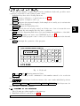
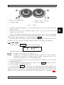
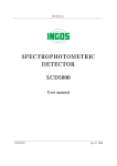
INGOS Ltd.
AUTOSAMPLER
LCS 5040
User manual
PRAGUE
Apr 11 2006
Producer
:
Laboratory Instruments division of INGOS Ltd.
Development
:
PiKRON Ltd.
Supplier and service
:
INGOS Ltd.
K Nouzovu 2090
14316 PRAGUE 4
CZECH REP.
(c) INGOS 2006
Tel: +420 296 781 683
+420 296 781 692
Fax: +420 244 403 051
e-mail:[email protected]
INTRODUCTION
CAPACITIES AND SPECIFICATIONS
PUTTING INTO OPERATION
OPERATION
DESCRIPTION OF THE AUTOSAMPLER
ACCESSORIES AND SPARE PARTS
WARRANTY
TABLE OF CONTENTS
1
2
3
4
5
6
7
8
1. INTRODUCTION
Autosampler LCS5040 is an apparatus designed for the dispensing of sample series to
the flow of the liquid chromatograph mobile phase. This apparatus can be controlled with
the help of the PC data station software by means of the RS232 or RS485 interface. In
cases when no intelligent software is available it is possible to control the sample sequence
and the start-up of the integrating system by using the timer program of the autosampler.
1
4
2
3
5
1. Dispensing valve
2. Arm with a needle
3. Disk with samples
4. Cover
5. Keyboard and display
Fig. 1. Autosampler
INGOS s.r.o.
Page 4
1
2. CAPACITIES AND SPECIFICATIONS
2.1 Capacities
The autosampler is fitted with a precise dispensing valve which is designed for pressure
up to 35 MPa.
As a sample stock it is possible to use a disk for 40 micro test-tubes (0.5 ml) or a
disk for 25 glass tubes VIAL (1 ml).
The disk test-tubes can be cooled down to 40 C (at an ambient temperature lower
than 280 C).
2.1.1 Communication
Autosampler can communicate with a master computer with the help of the serial
link RS485, possibly RS232.
In the use within a system which does not support computer communication it is
possible to use a simple type of communication with the help of several logical signals.
2.2 Specications
Samples . . . . . . . . . . . . . . . . . . . . . . . . . . . . . . . . . . 40 micro test-tubes 0.5 ml
closed with pricking covers
25 glass VIAL 1 ml closed
with Teflon sept
Sample cooling . . . . . . . . . . . . . . . . . . . . . . . . . . . optional max 240 C below
the ambient temperature
Dispensing loop . . . . . . . . . . . . . . . . . . . . . . . . . . .5 µl and higher
Sample consumption . . . . . . . . . . . . . . . . . . . . . . loop volume + 30 µl
Mobile phase pressure . . . . . . . . . . . . . . . . . . . . max 35 MPa
Materials in the contact . . . . . . . . . . . . . . . . . . stainless steel VESPEL, PEEK, TEFLON
with the mobile phase
Cycle duration . . . . . . . . . . . . . . . . . . . . . . . . . . . .max 600 min
Communication . . . . . . . . . . . . . . . . . . . . . . . . . . .RS485 or RS232
Output control signals . . . . . . . . . . . . . . . . . . . . . 4 (level TTL)
Retro reading of responses . . . . . . . . . . . . . . . . 2 (level TTL)
Dimensions (w x h x d) . . . . . . . . . . . . . . . . . . . 240 x 260 x 400mm
Weight . . . . . . . . . . . . . . . . . . . . . . . . . . . . . . . . . . . 15 kg
Power supply . . . . . . . . . . . . . . . . . . . . . . . . . . . . . 230 V, 10%, 50 Hz
Overvoltage class in the mains . . . . . . . . . . . . II.
Power input . . . . . . . . . . . . . . . . . . . . . . . . . . . . . . max. 80 VA
The apparatus is designed for environments with a temperature within the range
from 15 to 30 0 C; humidity up to 80 % without acid and caustic vapours. For the reason
of ventilation there must be free space of 0.15 m behind the apparatus.
For cooling purposes the apparatus draws air through the inlet aperture, which is
situated in the bottom part behind the keyboard panel. Therefore it must be put on a
hard pad in order to avoid the closing of the inlet aperture.
INGOS s.r.o.
Page 5
2
LCS 5040
Section 2: CAPACITIES AND SPECIFICATIONS
It is possible to connect the apparatus to the socket with a properly connected protective plug.
It is not allowed to use the apparatus in any manner other than those provided for
in the operating instructions, otherwise the protection provided by the system could be
interfered.
INGOS s.r.o.
Page 6
2
3. PUTTING INTO OPERATION
3.1 Unpacking
Unpack the autosampler from the transportation package. Check the external appearance of the apparatus and verify whether the apparatus has not suffered any visible
damage during transportation. If the apparatus was damaged during transport, contact
immediately the transport company.
According to the list of accessories (6.1) check all items. If the numbers do not correspond, check carefully all packing material. If any item is missing, please contact the
producer or your supplier.
Put the autosampler on the table and make yourself familiar with the arrangement
and functions of control and connection items. Before the first activation of the apparatus
read thoroughly the instructions concerning the operation of the apparatus, see Chapter
4.
3.1.1 What you need
In order to put the autosampler into operation you will need the following items:
1. Other parts of the liquid chromatograph: pump, column, detector.
2. Bottle with flushing liquids (distilled water).
3. Appropriate pipes and connection material serving for the connection of the autosampler and other instruments of the chromatograph.
3.2 Putting into operation of the autosampler
Putting into operation can depend on the assembly of the liquid chromatograph, type
of communication used and on a concrete type of interconnection.
In the following instructions it is presupposed to use the autosampler as individual
units, co-operating with the assembly of the liquid chromatograph only by means of
logical signals.
3.2.1 Hydraulic connection
Dispensing valve (fig. 2) shall be connected, with the pipes, to the mobile phase pump,
and to the column it will be connected with a metal pipe 1.6/0.3 (inlet of PUMPS and
COLUMN).
The waste system is fitted with tubing slid into the terminal outlet whose diameter
is 8 mm(fig. 3). The tubing must have a gradient oriented towards the waste container.
Peristaltic pump (fig. 2) of the autosampler is connected, with a Teflon tube 1.6 /0.8
mm connected to the container of the flushing liquid (distilled water).
Peristaltic pump is capable of pumping with two tubes. This can be advantageously
used for the flushing of pistons of the high-pressure pump of the series LCP5000.
3.2.2 Electrical connection
All connectors for electrical connection of the apparatus are situated on the rear panel
(fig. 3). The connectors used are not mutually interchangeable.
INGOS s.r.o.
Page 7
3
LCS 5040
Section 3: PUTTING INTO OPERATION
5
1
6
2
3
3
7
4
1.
2.
3.
4.
Sensor 1
Inlet for the column interconnection
Inlet for the pump connection
Dispensing valve
5. Inlet of flushing liquid
6. Sensor 2
7. Peristaltic pump
Fig. 2. Hydraulic system interconnection
Feeding voltage 230 V AC is conducted to the mains connection lead. The connection
lead is protected with the fuse T0.63A
If it is necessary to ensure connection to a computer it will be connected to the
communication system RS485 connector by means of the cable supplied.
If the autosampler controls peripheries through its logical outputs and inputs, the
supplier will supply a cable with the interconnection required, which is to be connected
to the AUX OUTPUT connector.
1
5
2
3
6
4
1. Aux output
2. Mains connection lead
3. Fuse
4. Switch
5. Communication RS485
6. Waste
Fig. 3. Rear panel
INGOS s.r.o.
Page 8
LCS 5040
Section 3: PUTTING INTO OPERATION
3.3 Keyboard and display
The two-line display, together with a 36-key membrane keyboard, provides user’s
comfort for both direct control and program control.
Individual keys have the following functions:
CAL Activates calibration of optical sensors, see 4.2.2.
PREP Prepares a sample to the loop.
LOAD Dispense the prepared sample, if the sample is not ready yet, it activates its
preparation and then dispenses.
INJECT Opens the dispensing valve.
STOP Cancels the action being carried out. In the case of error it resets the error
condition and puts the autosampler into the basic conditions.
FIX Fixes the dispensing disk driver. It is used during the installation of the disk.
STANDBY Passing from and to the STANDBY mode, see 4.1.
RUN Activates the program control of the cycle, if there is a program in the internal
memory.
END Interrupts the operation of the program.
LIQUID CHROMATOGRAPHY SAMPLER
MODE
PROG
7
8
9
4
5
6
2
3
SAMPLE
SETING
AUX
OUTPUT
CYCLE
TEMPER
F1
F2
F3
F4
1
RUN
END
CAL
PREP
LOAD
INJECT
STOP
FIX
STANDBY
0
ENTER
LCS 5040
Fig. 4. Keyboard
1 up to 0 and . Entering numerical data.
ENTER Key serving for the confirmation of the number entered or for a selection
from the menu.
Direction keys for the movement of the cursor under individual positions
of the display.
SAMPLE SETING AUX OUTPUT CYCLE TEMPER these keys serve for
the switching of individual displays.
3.3.1 Start-up of the apparatus
The following procedure applies to the start-up:
1. Establish electrical connection, see 3.2.2
INGOS s.r.o.
Page 9
3
LCS 5040
Section 3: PUTTING INTO OPERATION
2. Establish hydraulic connection 3.2.1.
3. Turn the apparatus on by means of the switch situated on the rear panel, see fig. 3,
after activation the apparatus will be in the STANDBY mode.
4. By using the key STANDBY pass to the working mode, see 4.1.
5. Insert samples, see 4.2.1.
6. Program the sequence, see 4.3.1.
7. Start the program sequence by using the key RUN .
3
INGOS s.r.o.
Page 10
4. OPERATION
on
1.
2.
3.
All functions of the apparatus are controlled with the help of the keyboard and display
the front panel.
Cursor movement. You can move the cursor by using the keys
. Cursor
does not move by individual characters but by the entries.
Entering numerical data. It is possible to change the entry under which cursor is
situated. Numerical data are entered by means of numerical keys. If it is necessary
to enter a negative number, use the key CTRL . After entering it is necessary to
confirm the number by using the key ENTER .
Selection from the menu. While selecting from the menu, move cursor to the required
entry, and carry out the selection by using the key ENTER İf the menu is longer,
you will see only two lines on the display, and the menu will scroll if you move the
cursor.
4.1 Standby
After activation the autosampler is in the STANDBY mode. This is a rest mode,
serving only for the cooling of samples. The apparatus provides cooling to the temperature
set for the last time, see 4.2.5.
The display shows apparatus identification, and the yellow LED of the key STANDBY
is lit.
By using the key STANDBY you will get to the working mode. By pressing this
key in the working mode you will get to the STANDBY mode.
While passing from the STANDBY mode to the working mode the calibration procedure will be activated on an automatic basis, see 4.2.2 .
4.2 Direct control
4.2.1 Insertion of samples
Samples in test-tubes are inserted to circular storage stands. The apparatus can be
fitted with two types of storage stands, according to test-tubes (fig. 5):
1. Disk for 40 micro test-tubes 0.5 ml closed with pricking covers
2. Disk for 25 glass VIAL 1 ml closed with a Teflon sept
Put the disk onto the drive in such a way that it can drop as low as possible, with
its pivots, into the five holes of the drive. Slide the ring with the groove downwards, by
applying even pressure, and you will attach the disk in the drive.
During the insertion of the disk it is possible to fix the drive against rotation by using
the key FIX .
4.2.2 Calibration
For the purpose of a correct functioning of the apparatus it is necessary to calibrate
optical sensors of the liquid. During this calibration also the dispensing loop, needle and
tubing are flushed.
Calibration is carried out in three steps :
INGOS s.r.o.
Page 11
4
LCS 5040
Section 4: OPERATION
1
3
2
4
1. Disk for test-tubes VIAL
2. Test-tube VIAL
3. Disk for micro test-tubes
4. Micro test-tube
Fig. 5. Disks
1. Peristaltic pump will flush the loop and needle with water. Sensors will measure the
value for water.
2. With its reverse mode the peristaltic pump will dry out the loop and sensors will
measure the value for air.
3. The loop will again be filled with water so that the system can be ready for dispensing.
Calibration will be activated automatically during the switch-over from the STANDBY mode to the working mode, or by using the key CAL .
The LED CAL is lit during calibration. If the LED turns off, it indicates the end of
calibration, if there appears a mistake during calibration, the LED starts flashing.
4.2.3 Dispensing
By using the key SAMPLE call the following display:
Sample
1
Status
Off
Individual symbols have the following meanings:
Sample Number of the sample to be dispensed.
Status
Condition of the dispensing system. Off The system is in a rest condition.
Working The system is working. Prepare Sample is prepared in the loop.
Error There appeared an error during dispensing.
The actual dispensing runs in two steps. First prepare a sample into the loop, then
proceed with dispensing.
Sample preparation will be activated by using the key PREP . During the preparation of the sample the LED PREP is lit.
By using the key LOAD you will carry out actual dispensing. If the sample is not
ready, carry out its preparation first, and then the dispensing. After dispensing the valve
will be closed back to its position, the peristaltic pump will flush the loop and the needle
with water. It is possible to pre-set the time of the dispensing valve opening, see 4.4.1.
INGOS s.r.o.
Page 12
4
LCS 5040
Section 4: OPERATION
It is possible to interrupt both dispensing and preparation by using the key STOP .
In the case there appears a mistake, the LED PREP or LOAD will be flashing and by
means of the key STOP you will reset the error condition.
4.2.4 Control inputs and outputs
By using the key AUX OUTPUT you will call the display serving for the control of
output commands and for the reading of retro responses.
AUX
-SOUTPUT 1234
-R56
The display shows the following data:
-SOutput commands. These are controlled by the numeric keyboard where the
pressing of the keys 1 to 4 calls the command and repeated pressing cancels
it.
-RRetro responses are only displayed.
4.2.5 Setting of the cooling temperature
By using the key TEMP you will activate the display for the setting of the cooling
temperature:
Temper
On
Fin Act
8.0 8.2
Individual symbols have the following meanings:
Temper On or Off turning on and off of the cooling system. You can switch over by
using the key ENTER .
Fin
Required temperature. This temperature can be pre-set.
Act
Current temperature. It is displayed only.
The setting of the cooling system is stored at the same time with other parameters,
see 4.4.1.
4.3 Program control
4.3.1 Setting of the number of cycles
The display of the setting of the number of cycles will be called by the key CYCLE .
Sample
1- 3
Rep Time
2 2.00
Individual symbols have the following meanings:
Sample Number of the first and last test-tubes of the sequence.
Rep
Number of drawings from one test-tube.
Time
Cycle duration in minutes.
The sequence entered can be stored and in such a case it remains to be pre-set even
if the apparatus is turned off.
INGOS s.r.o.
Page 13
4
LCS 5040
Section 4: OPERATION
During the run of a sequence it is possible to change only the number of the last
test-tube.
4.3.2 Program run
Start the run of the sequence set in the CYCLE mode by using the key RUN .
Pre-programmed sequence can be interrupted by using the key END .
By pressing the key SAMPLE during the program run it is possible to call the
information display:
Sample
5 2
Stat/Tim
2.35
Individual symbols have the following meanings:
Sample Number of the current test-tube and number of repeating.
Stat/Tim Conditions or time of analysis. During the preparation of a sample Working
is displayed, during the run of the analysis the time is displayed. If there is a
mistake, Error is displayed.
4.4 Setting of parameters
4.4.1 Menu SETING
Setting of basic parameters is carried out in the menu SETING. This menu is called
by pressing the key SETING .
Settings
Inject T
0.20
Fill Vol
300
Aux Off 1234
Aux Next 1234 56
Aux Rdy 1234
Aux Inj 1234
Aux Wait 1234
Aux End 1234
Manual Inj No
Save settings
Individual symbols have the following meanings:
Inject T
For the time during which the dispensing valve is opened see 4.2.3.
Fill Vol
Volume of sample which is drawn behind the first sensor before the needle
is slid out from the test-tube. For an exact description see the chapter 5.3.
If you set this volume too large, the sample consumption will rise, if you
set it too small, the dispensing procedure will end with an error. The right
volume is such that after the drawing of a sample into the loop (condition
Prepare) the tube in front of the first sensor should contain approximately
3 cm of liquid.
INGOS s.r.o.
Page 14
4
LCS 5040
Section 4: OPERATION
Other parameters serve for the communication of the dispenser with its surroundings
by means of logical inputs and outputs. Numbers 1 to 4 correspond to logical 1 on the
output in question, the character ” ” corresponds to log. 0. The output commands are
controlled by means of the numeric keyboard where the pressing of the keys 1 to 4 calls
the command and repeated pressing cancels it.
Aux O
Conditions of control commands if the dispensing system does not work.
Aux Next Conditions of control commands at the moment when the sample is prepared. Numbers 5 and 6 represent logical inputs. With the help of these
inputs it is possible to define the condition for the compliance of which the
apparatus is waiting after the sample preparation. Configuration of inputs
is controlled by using the keys 5 and 6 . If a number is displayed, it means that the system waits for the input to be in log. 1, the character ” ”
means waiting for log. 0 and the character ”x” says, that the value of the
input in question does not matter.
Aux Rdy
Conditions of control outputs at the moment when the sample is ready.
Aux Inj
Conditions of control outputs at the moment of dispensing.
Aux Inj
Conditions of control outputs at the moment of waiting.
Aux Inj
Conditions of control outputs at the completion of the sequence.
Manual Inj On or Off defines whether the output signals should be set even during
manual dispensing, see 4.2.3.
Save setting By pressing the key ENTER on this entry you will save the settings into
the permanent memory where it remains kept even if the apparatus is
turned off. During the saving of parameters you will also store the settings
for the cooling system (4.2.5)as well as the sequence parameter settings
(4.3.1).
4.4.2 Menu MODE
The setting of other parameters can be carried out by using the menu MODE. This
menu can be activated by pressing the key MODE .
Mode menu
Save setting
Communication
Service
Individual symbols have the following meanings:
Save setting
Saving of settings in the same way as in 4.4.1.
Communication Setting of serial communication parameters, see 4.4.3.
Service
Passage into the servicing mode.
4.4.3 Setting of communication
The communication setting display is activated through the menu MODE, see 4.4.2.
INGOS s.r.o.
Page 15
4
LCS 5040
Section 4: OPERATION
Type
uLAN
Adr
7
Spd
9600
Individual symbols have the following meanings:
Type
Serial communication type uLAN or RS232.
Adr
Apparatus address in the network µLAN.
Spd
Speed of the serial communication.
4.5 Routine maintenance and servicing
Cleaning of all external surfaces of the apparatus is carried out by using a flannel
cloth moistened in water with a little detergent. If the sample storage stand is removed, it
is suitable to wipe off the cooler groove as well. If it is necessary to clean also the internal
part of the apparatus, the work needs to be assigned to a service technician.
The only part with a reduced lifetime is formed by the peristaltic pump tubing. They
are loaded by pumping, and still more by tensioning through the pump head attachments,
even in standstill. The spare part kit contains replacement tubing. According to them
it is possible to carry out the assembly of new tubing, by using the basic material. The
length of a silicone tube (clearance 1 mm, wall thickness 0.5 mm) is 80 mm. Practical
lifetime is approximately 2 months. It is recommended to replace both the tubes at the
same time. Thus it is possible to identify the reliable flushing of the pump pistons, if it is
flushed, and thereby also the lifetime of the most important parts of the entire assembly
of the liquid chromatograph.
If the tubes connected are checked after the connection, the assembly system should
be safe until the next assembly. This applies to the connection with the use of metal
sealing rings delivered together with the apparatus.
If there is a failure in the dispensing valve tightness, the pressure liquid will leak into
the sample route, which can be registered by worsened reproducibility of results. This
valve can be replaced by the user. After the unscrewing of two screws next to the valve it
is possible to remove it. Thus also the dispensing loop is accessible. Valve repair is made
on a replacement basis, and the manufacturer will upgrade the old one.
INGOS s.r.o.
Page 16
4
5. DESCRIPTION OF THE AUTOSAMPLER
5.1 Mechanics
The system is assembled of the following groups positioned on the cabinet with standardised dimensions, serving for the modules of the chromatograph LC5000.
5.1.1 Disk with samples
The disk is designed for 40 micro test-tubes or 25 glasses VIAL with samples. Samples
are inserted into a removable disk situated above the ring cooler. If there is a requirement
relating to the preparation of an individual sample, the disk brings the test-tube selected
against the arm with a needle.
5.1.2 Arm with a needle
The assembly carries out a rotary movement and the needle moves in a vertical
direction up and down. In the basic position the arm is rotated in such a way that the
needle can be situated above the waste tube through which flushing water flows away. If
the preparation of a sample is requested, the arm rotates to above the test-tube selected.
The needle, moving downwards, will prick the test-tube cover and continues down to the
bottom. For further procedure see the dispensing sequence (5.3).
5.1.3 Dispensing valve
This is a classical dispensing valve with a loop. The servomechanism situated under
it provides for the valve opening from the position LOAD to the position INJECT and
vice versa. The valve is removable, and thus it is possible to get access to the loop. The
valve is adjusted for dispensing up to a maximum pressure of 35 MPa.
5.1.4 Optical sensors
Optical sensors check the presence of the liquid in the Teflon pipe. The filling of
the dispensing loop with the liquid is verified. Software which operates the sensors also
carries out their calibration, and therefore it is possible to use tubes of various internal
diameters. There are two sensors: in front of the dispensing valve loop and behind it.
5.1.5 Peristaltic pump
Peristaltic pump flushes residuals of the sample with water from the storage tank,
separates the sample with air, draws the sample through the needle, loop and sensors.
5.1.6 Cooling
The annular cooler is cooled by Peltier cells. The heat is taken off by means of air
passing through a fan. Air enters from below, behind the keyboard and exits through the
rear side. It is convenient to place the autosampler on the pump LCP5020. Entrance of
the cooling air is more permeable.
INGOS s.r.o.
Page 17
5
LCS 5040
Section 5: DESCRIPTION OF THE AUTOSAMPLER
5.1.7 Inlets
The mains connection lead with a fuse is situated on the rear side, together with a
switch. Logical outputs and inputs are conducted out with a seven-pin socket. The RS232
communication with a nine-pine delta connection can alternatively be replaced with a
couple of RS485 connectors. The terminal unit of the flushing liquid waste connection
is situated next to the mains connection lead. Also the drainage of the cooling coil is
conducted into this terminal unit.
5.1.8 Keyboard
Membrane keyboard, together with the display, makes it possible to obtain complete
information on dispensing, and makes it also possible to enter the sequence of the samples,
including the time of repeating.
5.2 Electronics
The basis of the autosampler electronic system is formed by two boards AA POD and
AA PPW. These boards are screwed to the cooler, and other parts of the feeder system
are connected to them by means of connectors. These other parts are: Arm with a board
AA RAM, peristaltic pump with a board AA PER, step motor of the disk with a board
AA OSP and dispenser with AA SWD and 2 AA opt. Besides, the board AA POD
controls the cooling system of the samples as well as the cooling system fan. The switch
of the sample cooling is directly in the source.
5.3 Dispensing sequence
The dispensing sequence runs on the following basis:
Needle is flushed with water.
Needle is dried out with air.
Disk is rotated into the position required.
Arm goes down and inserts the needle into the test-tube.
Sample is drawn, up to the first sensor.
Still further sample volume is drawn, it is defined by the constant. Fill Vol.
Arm rises upwards.
Sample is drawn, up to the loop.
Both sensors are checked for the presence of the sample.
The system waits for a command for actual dispensing (If you use the function LOAD
from the keyboard, the command will be generated automatically after the termination of the previous step).
Dispensing is carried out by the opening of the dispensing valve.
Waiting for the time defined by the constant Inject T.
Dispensing valve is closed back to its position.
Needle is flushed with water.
INGOS s.r.o.
Page 18
5
6. ACCESSORIES AND SPARE PARTS
6.1 Basic accessories
1
2
4
4
4
2
1
item Mains cord
items Fuse T0.63A
items Stainless steel screw, passing
items Metal sealing ring
items Passing screw PEEK
items Peristaltic system loop
m Silicone tube 2/1 mm
6.2 Other accessories
To the autosampler it is possible to order, on an optional basis, tailored interconnection cables according to the other components of the chromatograph.
Besides the above cables, it is also possible to order loops of various sizes.
6.3 Consumables
Micro test-tubes:
Type: K001298 (Ependorfka 0.5 ml)
Supplier: P-LAB Říčanská 10, PRAHA 10, PCN 10100
Office: Korunní 127 Fax: 71 73 11 76
Warehouse: Lucemburská 23 Tel: 71 73 08 00
Vial glasses:
Type: 1.1-STVG (1.1 ml Gold grade vial), covers type 8-310 115, septa Teflon 0.5
mm diameter 8 mm (supplied by INGOS)
Supplier: Chromservis s.r.o Na rovnosti 19, Praha 3, Tel: 02/6846731, Fax: 6973012.
INGOS s.r.o.
Page 19
6
7. WARRANTY
The autosampler LCS5040 is covered by the manufacturer’s warranty, for a period of
one year from the day of handing over of the product to the purchaser. The apparatus
can be used only in the way provided for in these instructions. The manufacturer will
not bear responsibility for any damage caused by failure to comply with the conditions
provided for in these instructions.
The dispensing valve of the autosampler is designed for the pumping of liquids used for
high-pressure liquid chromatography, which do not spoil the materials of the valve being
in contact with the liquid pumped. These are stainless steel 17246, PEEK??, TEFLON
??.
The apparatus is designed for environments featuring a temperature of 15 to 35 0 C;
humidity up to 80% without acid and caustic vapours. The operators must be instructed
with regard to safety regulations and work with the liquids used.
All warranty and after-warranty repairs shall be carried out by the manufacturer or
by an organisation authorised by the manufacturer.
7.1 Waste disposal
When the instruments operating life is over dispose it in respect to valid regulations,
also it can be returned to the vendor or producer for liquidation.
Warning: Instrument contains parts (PCB’s) which are rated as hazardous waste.
7
INGOS s.r.o.
Page 20
8. TABLE OF CONTENTS
1. INTRODUCTION . . . . . . . . . . . . . . . . . . . . . . . . . . . . . . . . . . . . . . . . . . . . . . . . . . . . . . . . . . . . . 4
2. CAPACITIES AND SPECIFICATIONS . . . . . . . . . . . . . . . . . . . . . . . . . . . . . . . . . . . . . . . . 5
2.1 Capacities . . . . . . . . . . . . . . . . . . . . . . . . . . . . . . . . . . . . . . . . . . . . . . . . . . . . . . . . . . . . . . . . 5
2.1.1 Communication . . . . . . . . . . . . . . . . . . . . . . . . . . . . . . . . . . . . . . . . . . . . . . . . . . . . 5
2.2 Specifications . . . . . . . . . . . . . . . . . . . . . . . . . . . . . . . . . . . . . . . . . . . . . . . . . . . . . . . . . . . . . 5
3. PUTTING INTO OPERATION . . . . . . . . . . . . . . . . . . . . . . . . . . . . . . . . . . . . . . . . . . . . . . . . 7
3.1 Unpacking . . . . . . . . . . . . . . . . . . . . . . . . . . . . . . . . . . . . . . . . . . . . . . . . . . . . . . . . . . . . . . . . 7
3.1.1 What you need . . . . . . . . . . . . . . . . . . . . . . . . . . . . . . . . . . . . . . . . . . . . . . . . . . . . . 7
3.2 Putting into operation of the autosampler . . . . . . . . . . . . . . . . . . . . . . . . . . . . . . . . . 7
3.2.1 Hydraulic connection . . . . . . . . . . . . . . . . . . . . . . . . . . . . . . . . . . . . . . . . . . . . . . . 7
3.2.2 Electrical connection . . . . . . . . . . . . . . . . . . . . . . . . . . . . . . . . . . . . . . . . . . . . . . . 7
3.3 Keyboard and display . . . . . . . . . . . . . . . . . . . . . . . . . . . . . . . . . . . . . . . . . . . . . . . . . . . . 9
3.3.1 Start-up of the apparatus . . . . . . . . . . . . . . . . . . . . . . . . . . . . . . . . . . . . . . . . . . . 9
4. OPERATION . . . . . . . . . . . . . . . . . . . . . . . . . . . . . . . . . . . . . . . . . . . . . . . . . . . . . . . . . . . . . . . . . 11
4.1 Standby . . . . . . . . . . . . . . . . . . . . . . . . . . . . . . . . . . . . . . . . . . . . . . . . . . . . . . . . . . . . . . . . . 11
4.2 Direct control . . . . . . . . . . . . . . . . . . . . . . . . . . . . . . . . . . . . . . . . . . . . . . . . . . . . . . . . . . . 11
4.2.1 Insertion of samples . . . . . . . . . . . . . . . . . . . . . . . . . . . . . . . . . . . . . . . . . . . . . . . 11
4.2.2 Calibration . . . . . . . . . . . . . . . . . . . . . . . . . . . . . . . . . . . . . . . . . . . . . . . . . . . . . . . 11
4.2.3 Dispensing . . . . . . . . . . . . . . . . . . . . . . . . . . . . . . . . . . . . . . . . . . . . . . . . . . . . . . . . 12
4.2.4 Control inputs and outputs . . . . . . . . . . . . . . . . . . . . . . . . . . . . . . . . . . . . . . . . 13
4.2.5 Setting of the cooling temperature . . . . . . . . . . . . . . . . . . . . . . . . . . . . . . . . 13
4.3 Program control . . . . . . . . . . . . . . . . . . . . . . . . . . . . . . . . . . . . . . . . . . . . . . . . . . . . . . . . . 13
4.3.1 Setting of the number of cycles . . . . . . . . . . . . . . . . . . . . . . . . . . . . . . . . . . . . 13
4.3.2 Program run . . . . . . . . . . . . . . . . . . . . . . . . . . . . . . . . . . . . . . . . . . . . . . . . . . . . . . 14
4.4 Setting of parameters . . . . . . . . . . . . . . . . . . . . . . . . . . . . . . . . . . . . . . . . . . . . . . . . . . . . 14
4.4.1 Menu SETING . . . . . . . . . . . . . . . . . . . . . . . . . . . . . . . . . . . . . . . . . . . . . . . . . . . . 14
4.4.2 Menu MODE . . . . . . . . . . . . . . . . . . . . . . . . . . . . . . . . . . . . . . . . . . . . . . . . . . . . . 15
4.4.3 Setting of communication . . . . . . . . . . . . . . . . . . . . . . . . . . . . . . . . . . . . . . . . . 15
4.5 Routine maintenance and servicing . . . . . . . . . . . . . . . . . . . . . . . . . . . . . . . . . . . . . . 16
5. DESCRIPTION OF THE AUTOSAMPLER . . . . . . . . . . . . . . . . . . . . . . . . . . . . . . . . . . 17
5.1 Mechanics . . . . . . . . . . . . . . . . . . . . . . . . . . . . . . . . . . . . . . . . . . . . . . . . . . . . . . . . . . . . . . . 17
5.1.1 Disk with samples . . . . . . . . . . . . . . . . . . . . . . . . . . . . . . . . . . . . . . . . . . . . . . . . . 17
5.1.2 Arm with a needle . . . . . . . . . . . . . . . . . . . . . . . . . . . . . . . . . . . . . . . . . . . . . . . . 17
5.1.3 Dispensing valve . . . . . . . . . . . . . . . . . . . . . . . . . . . . . . . . . . . . . . . . . . . . . . . . . . 17
5.1.4 Optical sensors . . . . . . . . . . . . . . . . . . . . . . . . . . . . . . . . . . . . . . . . . . . . . . . . . . . . 17
5.1.5 Peristaltic pump . . . . . . . . . . . . . . . . . . . . . . . . . . . . . . . . . . . . . . . . . . . . . . . . . . 17
5.1.6 Cooling . . . . . . . . . . . . . . . . . . . . . . . . . . . . . . . . . . . . . . . . . . . . . . . . . . . . . . . . . . . 17
5.1.7 Inlets . . . . . . . . . . . . . . . . . . . . . . . . . . . . . . . . . . . . . . . . . . . . . . . . . . . . . . . . . . . . . 18
5.1.8 Keyboard . . . . . . . . . . . . . . . . . . . . . . . . . . . . . . . . . . . . . . . . . . . . . . . . . . . . . . . . . 18
5.2 Electronics . . . . . . . . . . . . . . . . . . . . . . . . . . . . . . . . . . . . . . . . . . . . . . . . . . . . . . . . . . . . . . 18
5.3 Dispensing sequence . . . . . . . . . . . . . . . . . . . . . . . . . . . . . . . . . . . . . . . . . . . . . . . . . . . . . 18
INGOS s.r.o.
Page 21
8
LCS 5040
Section 8: TABLE OF CONTENTS
6. ACCESSORIES AND SPARE PARTS . . . . . . . . . . . . . . . . . . . . . . . . . . . . . . . . . . . . . . . .
6.1 Basic accessories . . . . . . . . . . . . . . . . . . . . . . . . . . . . . . . . . . . . . . . . . . . . . . . . . . . . . . . .
6.2 Other accessories . . . . . . . . . . . . . . . . . . . . . . . . . . . . . . . . . . . . . . . . . . . . . . . . . . . . . . . .
6.3 Consumables . . . . . . . . . . . . . . . . . . . . . . . . . . . . . . . . . . . . . . . . . . . . . . . . . . . . . . . . . . . .
7. WARRANTY . . . . . . . . . . . . . . . . . . . . . . . . . . . . . . . . . . . . . . . . . . . . . . . . . . . . . . . . . . . . . . . . .
7.1 Waste disposal . . . . . . . . . . . . . . . . . . . . . . . . . . . . . . . . . . . . . . . . . . . . . . . . . . . . . . . . . .
8. TABLE OF CONTENTS . . . . . . . . . . . . . . . . . . . . . . . . . . . . . . . . . . . . . . . . . . . . . . . . . . . . .
8.1 List of picturtes and tables . . . . . . . . . . . . . . . . . . . . . . . . . . . . . . . . . . . . . . . . . . . . . .
19
19
19
19
20
20
21
22
8.1 List of picturtes and tables
Fig.
Fig.
Fig.
Fig.
Fig.
1.
2.
3.
4.
5.
Autosampler . . . . . . . . . . . . . . . . . . . . . . . . . . . . . . . . . . . . . . . . . . . . . . . . . . . . . . . . . . . . . . . 4
Hydraulic system interconnection . . . . . . . . . . . . . . . . . . . . . . . . . . . . . . . . . . . . . . . . . . . 8
Rear panel . . . . . . . . . . . . . . . . . . . . . . . . . . . . . . . . . . . . . . . . . . . . . . . . . . . . . . . . . . . . . . . . . 8
Keyboard . . . . . . . . . . . . . . . . . . . . . . . . . . . . . . . . . . . . . . . . . . . . . . . . . . . . . . . . . . . . . . . . . . 9
Disks . . . . . . . . . . . . . . . . . . . . . . . . . . . . . . . . . . . . . . . . . . . . . . . . . . . . . . . . . . . . . . . . . . . . . 12
8
INGOS s.r.o.
Page 22


![,QKDOWVYHU]HLFKQLV - Schwimmbecken Grosshandel](http://vs1.manualzilla.com/store/data/006796368_1-fd7fec9446d0e6d8cca5d856625bdbd4-150x150.png)