1
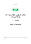
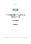
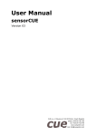
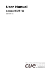
INGOS s.r.o.
VACUUM PUMP CONTROL
FOR RVO 200 A
User manual
PRAHA
8. srpna 2002
Producer
:
INGOS
Supplier and service
:
INGOS s.r.o.
K Nouzovu 2090
14316 PRAHA 4
(c) INGOS 2002
Tel: +420 2 96781683
+420 2 96781692
Fax: +420 2 44403051
e-mail:[email protected]
INTRODUCTION
PUTTING INTO OPERATION
CONCLUSION
TABLE OF CONTENTS
1
2
3
4
1
1. INTRODUCTION
1.1 Apparatus use and specications
The control system of the vacuum pump is an additional device to RVO 200A and is
designed for controlling the operation of the motor vacuum pump. The control system
of the vacuum pump, in connection with RVO 200A makes it possible to control the
level of underpressure. This is very convenient for evaporation of heavily volatising
substances.
1.2 Technical characteristics
Switching output . . . . . . . . . . . . . . . . . . . . . . . . . max. 650 VA
Power supply . . . . . . . . . . . . . . . . . . . . . . . . . . . . . 230V, 10%, 50Hz
Category of overvoltage in the installation .II.
Weight without glass . . . . . . . . . . . . . . . . . . . . . 0.5 kg
Dimensions (w x h x d) . . . . . . . . . . . . . . . . . . . 160 x 80 x 50 mm
Fuse . . . . . . . . . . . . . . . . . . . . . . . . . . . . . . . . . . . . . . T 3.15 A
1.3 Technical description
2
3
4
1
1. Box
2. Inlet cord
INGOS s.r.o.
3. Socket for connection of the control
signal
4. Switched socket
Fig. 1. Vacuum pump control
Page 4
2. PUTTING INTO OPERATION
2.1 Unpacking
Take the control system out of the transportation package, check its surface and check
the delivery for completeness by using the delivery note. If it is damaged or if an item
is missing, contact the manufacturer or your supplier.
2.2 Assembly
1.
2.
3.
4.
RVO
Vacuum pump
Vacuum pump control
Interconnection cable
5.
6.
7.
8.
Control socket
Switched socket
Socket for vacuum pump control
”T” fitting
Fig. 2. Interconnection
1. Make the assembly of the vacuum pump control system and interconnection between the control system and RVO 200A (fig. 2). Connect the interconnection
cable (4) into the socket (7) RVO 200A and to the control socket of the control
system (5). Connect the vacuum pump (7) to the switched socket (6) featuring a
maximum power output of 650 VA.
2. Connect the mains cord.
INGOS s.r.o.
Page 5
2
RVO 200 A
Section 2: PUTTING INTO OPERATION
Caution
It is allowed to connect into the switched socket only the equipment complying
with the requirements imposed on safety and electromagnetic compatibility according
to ČSN and possibly ICE and CEE. It is allowed to connect into the interconnection
cable socket (5 and 7) only the interconnection cable delivered by the manufacturer.
2.3 Control system
The control system of the vacuum pump is put into operation from the RVO 200A
keyboard according to the RVO 200A instructions.
2.4 Maintenance
Do not allow that the surface be contaminated with corrosive substances. Clean the
surface of the apparatus with a clean soft cloth. the cloth can be moistened but not
wet. For cleaning purposes it is possible to use also ordinary washing means.
Caution: Before cleaning with a moistened piece of cloth, disconnect the system from the
mains!
2.5 Operation conditions
The control system is designed for work under ordinary laboratory conditions at temperatures from 10 to 30?C and air humidity up to 80
INGOS s.r.o.
Page 6
2
3. CONCLUSION
3.1 Repairs
All warranty and after-warranty repairs shall be carried out by the manufacturer or by
the organisation authorised by them. If the delivery note does not state otherwise,
contact the manufacture for any repair requirements.
3.2 Warranty
The product is covered by the manufacturer’s warranty lasting for one year from the day
of the handing over to the customer of the product. The apparatus can only be used
in the way specified in these instructions. The apparatus cannot be used in any other
way than as provided for in these instructions, otherwise the operation safety could
be interfered. If the conditions of these instructions are not met, the manufacturer
will not be liable for damages which could arise.
INGOS s.r.o.
Page 7
3
4. TABLE OF CONTENTS
1. INTRODUCTION . . . . . . . . . . . . . . . . . . . . . . . . . . . . . . . . . . . . . . . . . . . . . . . . . . . . . . . . . . . . .
1.1 Apparatus use and specifications . . . . . . . . . . . . . . . . . . . . . . . . . . . . . . . . . . . . . . . . . .
1.2 Technical characteristics . . . . . . . . . . . . . . . . . . . . . . . . . . . . . . . . . . . . . . . . . . . . . . . . . .
1.3 Technical description . . . . . . . . . . . . . . . . . . . . . . . . . . . . . . . . . . . . . . . . . . . . . . . . . . . . .
2. PUTTING INTO OPERATION . . . . . . . . . . . . . . . . . . . . . . . . . . . . . . . . . . . . . . . . . . . . . . . .
2.1 Unpacking . . . . . . . . . . . . . . . . . . . . . . . . . . . . . . . . . . . . . . . . . . . . . . . . . . . . . . . . . . . . . . . .
2.2 Assembly . . . . . . . . . . . . . . . . . . . . . . . . . . . . . . . . . . . . . . . . . . . . . . . . . . . . . . . . . . . . . . . . .
2.3 Control system . . . . . . . . . . . . . . . . . . . . . . . . . . . . . . . . . . . . . . . . . . . . . . . . . . . . . . . . . . .
2.4 Maintenance . . . . . . . . . . . . . . . . . . . . . . . . . . . . . . . . . . . . . . . . . . . . . . . . . . . . . . . . . . . . .
2.5 Operation conditions . . . . . . . . . . . . . . . . . . . . . . . . . . . . . . . . . . . . . . . . . . . . . . . . . . . . .
3. CONCLUSION . . . . . . . . . . . . . . . . . . . . . . . . . . . . . . . . . . . . . . . . . . . . . . . . . . . . . . . . . . . . . . . .
3.1 Repairs . . . . . . . . . . . . . . . . . . . . . . . . . . . . . . . . . . . . . . . . . . . . . . . . . . . . . . . . . . . . . . . . . . .
3.2 Warranty . . . . . . . . . . . . . . . . . . . . . . . . . . . . . . . . . . . . . . . . . . . . . . . . . . . . . . . . . . . . . . . . .
4. TABLE OF CONTENTS . . . . . . . . . . . . . . . . . . . . . . . . . . . . . . . . . . . . . . . . . . . . . . . . . . . . . .
4.1 List of picturtes and tables . . . . . . . . . . . . . . . . . . . . . . . . . . . . . . . . . . . . . . . . . . . . . . .
4.1 List of picturtes and tables
4
4
4
4
5
5
5
6
6
6
7
7
7
8
8
Fig. 1. Vacuum pump control . . . . . . . . . . . . . . . . . . . . . . . . . . . . . . . . . . . . . . . . . . . . . . . . . . . . . . 4
Fig. 2. Interconnection . . . . . . . . . . . . . . . . . . . . . . . . . . . . . . . . . . . . . . . . . . . . . . . . . . . . . . . . . . . . . 5
INGOS s.r.o.
Page 8
4