1
2520
Pulsed Laser Diode Test System
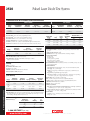
Ordering Information
2520
Pulsed Laser Diode
Test System with
Remote Test Head
Multi-channel pulsed
Side Text
test of laser diodes
2520/KIT1
Pulsed Laser Diode
Measurement Kit
(includes 2520, 2520INT,
and 3 ft. triax cable)
Accessories Supplied
User’s Manual, Quick Reference
Guide, Triax Cables (2),
BNC 10Ω Coaxial Cables (4)
ACCESSORIES AVAILABLE
2520INT-1-GE
7007-1
7007-2
KPCI-488LPA
KUSB-488B
Integrating Sphere (1 inch) with Germanium
Detector
Double Shielded GPIB Cable, 1m (3.3 ft.)
Double Shielded GPIB Cable, 2m (6.6 ft.)
IEEE-488 Interface/Controller for the PCI Bus
IEEE-488 USB-to-GPIB Adapter for USB Port
SERVICES AVAILABLE
2520-3Y-EW
1-year factory warranty extended to 3 years from
date of shipment
C/2520-3Y-DATA 3 (Z540-1 compliant) calibrations within 3 years
of purchase*
*Not available in all countries
identifies the settled region of the pulsed waveforms measured. This means the Model 2520 stores
only that portion of the pulse that is “flat” and contains meaningful data. All measurements made in
the flat portion of the pulse are averaged to improve the Signal-to-Noise ratio still further. If greater
resolution is required, the Model 2520 can be programmed to perform several pulse and measure
cycles at the same pulse amplitude. By making it possible to conduct more thorough testing at the
bar or chip level, the Model 2520 also eliminates the wasted time and costs associated with assembling then scrapping modules with non-compliant diodes.
Simple, One-Box Test Solution
The Model 2520 offers three channels of source and measurement circuitry. All three channels are
controlled by a single digital signal processor (DSP), which ensures tight synchronization of the
sourcing and measuring functions. The laser diode drive channel provides a current source coupled
with voltage measurement capability. Each of the two photodetector channels supplies an adjustable
voltage bias and voltage compliance, in addition to current measurement capability. These three
channels provide all the source and measure capabilities needed for full LIV characterization of laser
diodes prior to integration into temperature controlled modules. By eliminating the need for GPIB
commands to perform test sweeps with multiple separate instruments, the Model 2520’s integrated
sourcing and measurement allows a significant improvement in throughput.
Remote Test Head Maximizes Signal-to-Noise Ratio
The mainframe and remote test head architecture of the Model 2520 is designed to enhance pulsed
measurement accuracy, even at the sub-microsecond level. The remote test head ensures the measurement circuitry is located near the DUT, mounted on the fixture, minimizing cable effects. As the
schematic in Figure 1 shows, traditional semi-custom systems typically employed in the past require
significant integration. The architecture of the Model 2520 (Figure 2) offers a far more compact and
ready-to-use solution.
High Speed Pulse and Measure to Minimize Thermal Effects
The Model 2520 can accurately source and measure pulses as short as 500 nanoseconds to minimize
unwanted thermal effects during LIV testing. Users can program the pulse width from 500ns to 5ms
and pulse off time from 20µs to 500ms. There is a software duty cycle limit of 4% for currents higher
than 1A. To ensure greater accuracy, the instrument provides pulse width programming resolution
levels of 10µs (off time) and 100ns (on time).
Prior to the introduction of the Model 2520, test instrument limitations often placed barriers on test
performance. However, with the Model 2520, the limiting factor is not the test instrument, but the
Model 2520
High-Speed
Current to
Voltage
Converter
OPTOELECTRONICS TEST
Sequencing
and Signal
Analysis
Computer
High-Speed
Multi-Channel
Oscilloscope
Pulse
Source
GPIB
High-Speed
Current to
Voltage
Converter
High-Speed
Current to
Voltage
Converter
Front
Facet
Detector
Voltage Measure
Sequencing
and Signal
Analysis
DSP
Laser Diode
Chip or Bar
Rear
Facet
Detector
High-Speed
Multi-Channel
Digitizer
Pulse I
Source
Parallel Custom Bus
High-Speed
Current to
Voltage
Converter
Figure 1. This schematic reflects the current testing practices of
major laser diode manufacturers. Note that the use of discrete test
components increases the integration and programming effort, while
severely limiting the flexibility of the test system.
1.888.KEITHLEY (U.S. only)
w w w.keithley.com
Remote Test Head
2520INT
Laser Diode
Chip or Bar
Rear
Facet
Detector
Figure 2. The Model 2520 integrates synchronization, source, and
measure capabilities in a single half-rack instrument (with remote
test head) to provide maximum flexibility and test throughput.
A
G R E A T E R
M E A S U R E
O F
C O N F I D E N C E