1
2520
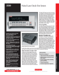
Pulsed Laser Diode Test System
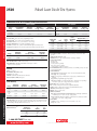
0.6
Full Pulse
0.5
1. 1 year, 23°C ±5°C.
2. If Duty Cycle · I exceeds 0.2, accuracy specifications must be derated with an additional error term as follows:
500mA Range: ±0.1% rdg. · D · I
5A Range:
±0.3% rdg. · D · I
where:
I = current setting
D = duty cycle
This derating must also be applied for a period equal to the time that D · I was ≥0.2.
3. Not including overshoot and setting time.
4. Pulse mode only.
5. Output: 500mA DC on 500mA range and 1A DC on 5A range.
6. Refer to Model 2520 Service Manual for test setup of current accuracy.
7. Figures 1 and 2 are typical pulse outputs into resistive loads.
8. Typical.
9. Per ANSI/IEEE Std 181-1977.
10. Per ANSI/IEEE Std 181-1977 10% to 90%.
11. DC accuracy ±700mV @ output terminal. 0.2Ω typical output impedance.
12. At DC, 10µs measurement pulse width, filter off.
13. Standard deviation of 10,000 readings with 10µs pulse width, filter off, with I source set to 0A DC.
14. The A/D converter has 14 bit resolution. The useful resolution is improved by reading averaging. The useful
resolution is:
0.515
0.51
0.4
0.505
Expanded Pulse Top
Current
0.3
(A)
Current
(A)
0.5
0.2
0.495
0.1
0.49
0.485
25
0
0
5
10
15
Time (μs)
20
Figure 1
Pulse Waveform Flatness - 5A into 2 Ohms
6
Full Pulse
5
5.04
4
5.02
Expanded Pulse Top
Current
3
(A)
5
2
4.98
1
4.96
0
0
5
Useful Resolution =
5.06
10
15
Time (μs)
20
Range
·
214
1
Pulse Width (ns) – 400ns
· Averaging Filter Setting
100ns
15. Excluding total programmed (Pulse ON time + Pulse OFF time).
16. Front panel off, calc off, filter off, duty cycle <10%, binary communications.
17. Returning 1 voltage and 2 current measurements for each source point.
18. Sweep mode.
19. Valid for both continuous pulse and sweep modes.
20. Shown is the Power Distribution % based on current settings.
21. Timing Cycle (pw⁄(pw + pd)): 4% max.
Current
(A)
Model
2520
specifications
Model
Side
specifications
Text
NOTES
Pulse Waveform Flatness - 500mA into 20 Ohms
4.94
25
Figure 2
Pulse Output/Trigger Output Relationship
6
Trigger
5
4
3
Volts
2
1
0
Pulse
-1
-2
-1.00E-06
-5.00E-07
0.00E+00
5.00E-07
1.00E-06
1.50E-06
OPTOELECTRONICS TEST
Time
Figure 3
1.888.KEITHLEY (U.S. only)
w w w.keithley.com
A
G R E A T E R
M E A S U R E
O F
C O N F I D E N C E