1
FH D
Fachhochschule Düsseldorf
University of Applied Sciences
Harvesting-Combine-Flow Simulation Technique
FMDauto
Institut für Produktentwicklung
und Innovation
Page 2/14
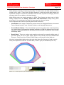
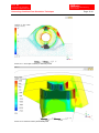
Meshing tool ICEM-CFD is used for meshing. This involves various important steps to be
realized during meshing. Geometry was imported from CAD software i.e. Autodesk Inventor
and it was modified accordingly.
-
Whole body is defined into different parts by grouping of geometric entities which allows us
to assign different parameters and boundary conditions on the individual parts.
-
Even these can be used to define different parameters on individual curves and surfaces.
-
Using these prescribed points and surfaces, the locations of tetrahedral nodes and edges
in the critical areas of the mesh are controlled.
-
Besides this, various factors like mesh smoothness and fineness are dealt with ease.
Repairing Geometry
-
“Build Topology” tool is executed which creates a series of curves and points from surface
edges depending on the proximity of surface edges to each other.
-
If the curves are within a geometric tolerance, they are merged together as one. This
tolerance is approximately one-tenth of the size of the average mesh size.
-
This tool helps us to diagnose the model for geometrical problems like gaps and holes.
They take automatic colours to show their association to adjacent surfaces.
-
If any geometrical problem found, then various tools like fill, blend, trim, match/stitch edges
etc. are used to fix these problems.
2.2
Meshing Requirements
Here combination of Tetra and Prism elements is preferred over Hexahedral element
because:
-
Despite of more efficiency and accuracy of hexahedral meshes (in terms of grid size),
these meshes are highly difficult to generate and time consumption is considerably higher
than generating a tet-prism combo mesh.
-
Combination of Tetra and Prism can easily mesh even complex geometries without
affecting accuracy very much.
-
Tetra elements are generally used for volume meshing while closer to boundary prismatic
elements are used for better meshing.
-
Regions where boundary layer effects are to be resolved, sometimes excessively fine
grids are needed close to the wall.
2.3
Meshing Parameters