1
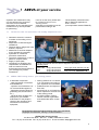
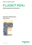
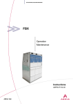
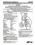
MEDIUM VOLTAGE SWITCHGEAR
FP Circuit Breaker with SF6 gas
insulation
Installation
Commissioning
Operation
Maintenance
Instructions
T&D
Table of contents
1
AREVA at your service . . . . . . . . . . . . . . . . . . . . . . . . . . . . . . . . . . . . . . . . . . . . . . . . . .
1
1.1
1.2
Our Service Unit: our specialists, and suitably adapted services... . . . . . . . . . . . . . . . . . . . . . . . . . . . .
AREVA T&D Training Centre: your training partner . . . . . . . . . . . . . . . . . . . . . . . . . . . . . . . . . . . . . . . . .
1
1
2
With regards to this User Manual . . . . . . . . . . . . . . . . . . . . . . . . . . . . . . . . . . . . . . . .
2
2.1
2.2
2.3
2.4
2.5
2.6
2.7
2.8
Eco-design concept and revalorisation of the materials used . . . . . . . . . . . . . . . . . . . . . . . . . . . . . . . . .
Responsibilities . . . . . . . . . . . . . . . . . . . . . . . . . . . . . . . . . . . . . . . . . . . . . . . . . . . . . . . . . . . . . . . . . . . . . . . .
Reminder concerning normal service conditions (in accordance with IEC 60694) . . . . . . . . . . . . . . .
* Permissible ambient temperature . . . . . . . . . . . . . . . . . . . . . . . . . . . . . . . . . . . . . . . . . . . . . . . . . . . . . . .
* Installation altitude . . . . . . . . . . . . . . . . . . . . . . . . . . . . . . . . . . . . . . . . . . . . . . . . . . . . . . . . . . . . . . . . . . . .
* Atmospheric pollution . . . . . . . . . . . . . . . . . . . . . . . . . . . . . . . . . . . . . . . . . . . . . . . . . . . . . . . . . . . . . . . . .
* Permissible atmospheric humidity level . . . . . . . . . . . . . . . . . . . . . . . . . . . . . . . . . . . . . . . . . . . . . . . . . .
Particular instructions for operation and intervention with energized equipment . . . . . . . . . . . . . . . . .
Other technical notices to be consulted . . . . . . . . . . . . . . . . . . . . . . . . . . . . . . . . . . . . . . . . . . . . . . . . . . .
Tools and products (not supplied) required for the operations described in this notice . . . . . . . . . . . .
Symbols & conventions . . . . . . . . . . . . . . . . . . . . . . . . . . . . . . . . . . . . . . . . . . . . . . . . . . . . . . . . . . . . . . . . .
Tightening torque values for standard assemblies (nut + bolt) . . . . . . . . . . . . . . . . . . . . . . . . . . . . . . . .
2
2
2
2
2
2
2
3
3
3
4
4
3
Presentation of the FP circuit breaker . . . . . . . . . . . . . . . . . . . . . . . . . . . . . . . . . . . .
5
3.1
Weights and shipping methods for the circuit breakers . . . . . . . . . . . . . . . . . . . . . . . . . . . . . . . . . . . . . .
5
4
Packaging - Handling - Storage . . . . . . . . . . . . . . . . . . . . . . . . . . . . . . . . . . . . . . . . . .
6
4.1
4.2
4.3
4.4
4.5
4.6
4.7
4.8
4.9
Transport - Delivery . . . . . . . . . . . . . . . . . . . . . . . . . . . . . . . . . . . . . . . . . . . . . . . . . . . . . . . . . . . . . . . . . . . .
Packaging for the circuit breakers . . . . . . . . . . . . . . . . . . . . . . . . . . . . . . . . . . . . . . . . . . . . . . . . . . . . . . . .
Packaging for the Circuit Breaker" moving part . . . . . . . . . . . . . . . . . . . . . . . . . . . . . . . . . . . . . . . . . . . .
Handling the circuit breaker when packed . . . . . . . . . . . . . . . . . . . . . . . . . . . . . . . . . . . . . . . . . . . . . . . . .
Storage conditions . . . . . . . . . . . . . . . . . . . . . . . . . . . . . . . . . . . . . . . . . . . . . . . . . . . . . . . . . . . . . . . . . . . . .
Intervention levels . . . . . . . . . . . . . . . . . . . . . . . . . . . . . . . . . . . . . . . . . . . . . . . . . . . . . . . . . . . . . . . . . . . . .
Specific recommendations for storage durations of less than 6 months . . . . . . . . . . . . . . . . . . . . . . . .
Specific recommendations for storage durations of between 6 and 12 months . . . . . . . . . . . . . . . . . .
Specific recommendations for storage durations of between 12 and 24 months . . . . . . . . . . . . . . . . .
6
6
6
7
8
8
8
8
8
5
Unpacking the circuit breaker . . . . . . . . . . . . . . . . . . . . . . . . . . . . . . . . . . . . . . . . . . .
9
5.1
5.2
5.3
5.4
Unpacking the circuit breaker . . . . . . . . . . . . . . . . . . . . . . . . . . . . . . . . . . . . . . . . . . . . . . . . . . . . . . . . . . . .
Identification of the circuit breaker . . . . . . . . . . . . . . . . . . . . . . . . . . . . . . . . . . . . . . . . . . . . . . . . . . . . . . . .
Identification of the circuit breaker with reduced pressure . . . . . . . . . . . . . . . . . . . . . . . . . . . . . . . . . . . .
Handling the circuit breaker when unpacked . . . . . . . . . . . . . . . . . . . . . . . . . . . . . . . . . . . . . . . . . . . . . . .
9
10
10
10
6
Installation outside the Functional Unit . . . . . . . . . . . . . . . . . . . . . . . . . . . . . . . . . .
12
6.1
6.2
Dimensions of the circuit breakers . . . . . . . . . . . . . . . . . . . . . . . . . . . . . . . . . . . . . . . . . . . . . . . . . . . . . . .
Dimensions for circuit breakers on the ground . . . . . . . . . . . . . . . . . . . . . . . . . . . . . . . . . . . . . . . . . . . . .
12
14
i
7
Adjustment of the SF6 gas pressure . . . . . . . . . . . . . . . . . . . . . . . . . . . . . . . . . . . . .
15
7.1
7.2
7.3
7.4
7.5
7.6
7.7
General instructions for handling and storing gas bottles under pressure . . . . . . . . . . . . . . . . . . . . . .
SF6 filling and pressure checking kit (supplied as an option) . . . . . . . . . . . . . . . . . . . . . . . . . . . . . . . . .
Preparation of the pressure adjustment tools . . . . . . . . . . . . . . . . . . . . . . . . . . . . . . . . . . . . . . . . . . . . . .
General instructions for pressure adjustment . . . . . . . . . . . . . . . . . . . . . . . . . . . . . . . . . . . . . . . . . . . . . .
Pressure adjustment procedure . . . . . . . . . . . . . . . . . . . . . . . . . . . . . . . . . . . . . . . . . . . . . . . . . . . . . . . . . .
Reminder of the SF6 gas volumes and pressures depending on the circuit breakers . . . . . . . . . . . .
Pressure ć Temperature Diagram . . . . . . . . . . . . . . . . . . . . . . . . . . . . . . . . . . . . . . . . . . . . . . . . . . . . . . . .
15
15
15
16
16
17
18
8
Commissioning - Operation . . . . . . . . . . . . . . . . . . . . . . . . . . . . . . . . . . . . . . . . . . . . .
19
8.1
8.2
8.3
8.4
Precautions to be taken before commissioning . . . . . . . . . . . . . . . . . . . . . . . . . . . . . . . . . . . . . . . . . . . . .
Electrical connection of the BLR control mechanism . . . . . . . . . . . . . . . . . . . . . . . . . . . . . . . . . . . . . . . .
Testing the operation of the circuit breaker . . . . . . . . . . . . . . . . . . . . . . . . . . . . . . . . . . . . . . . . . . . . . . . .
Operation of the circuit breaker . . . . . . . . . . . . . . . . . . . . . . . . . . . . . . . . . . . . . . . . . . . . . . . . . . . . . . . . . .
19
19
19
19
9
Maintenance ć Spare Parts . . . . . . . . . . . . . . . . . . . . . . . . . . . . . . . . . . . . . . . . . . . . . .
20
9.1
9.2
9.3
9.4
9.5
9.6
9.7
9.8
9.9
9.10
Levels of maintenance . . . . . . . . . . . . . . . . . . . . . . . . . . . . . . . . . . . . . . . . . . . . . . . . . . . . . . . . . . . . . . . . . .
General Instructions . . . . . . . . . . . . . . . . . . . . . . . . . . . . . . . . . . . . . . . . . . . . . . . . . . . . . . . . . . . . . . . . . . . .
Maintenance of the BLR ć BLRM control mechanism . . . . . . . . . . . . . . . . . . . . . . . . . . . . . . . . . . . . . . .
Standard maintenance of the circuit breaker" part . . . . . . . . . . . . . . . . . . . . . . . . . . . . . . . . . . . . . . . . . .
Systematic preventive maintenance . . . . . . . . . . . . . . . . . . . . . . . . . . . . . . . . . . . . . . . . . . . . . . . . . . . . . .
Maintenance following an intensive operating rhythm . . . . . . . . . . . . . . . . . . . . . . . . . . . . . . . . . . . . . . .
Pole linkage lubrication points . . . . . . . . . . . . . . . . . . . . . . . . . . . . . . . . . . . . . . . . . . . . . . . . . . . . . . . . . . .
Recommendations for the poles of the circuit breaker . . . . . . . . . . . . . . . . . . . . . . . . . . . . . . . . . . . . . . .
Corrective maintenance . . . . . . . . . . . . . . . . . . . . . . . . . . . . . . . . . . . . . . . . . . . . . . . . . . . . . . . . . . . . . . . .
Spare parts . . . . . . . . . . . . . . . . . . . . . . . . . . . . . . . . . . . . . . . . . . . . . . . . . . . . . . . . . . . . . . . . . . . . . . . . . . .
20
20
20
20
21
21
21
21
21
21
10
Replacement of a pole . . . . . . . . . . . . . . . . . . . . . . . . . . . . . . . . . . . . . . . . . . . . . . . . . .
22
General Instructions . . . . . . . . . . . . . . . . . . . . . . . . . . . . . . . . . . . . . . . . . . . . . . . . . . . . . . . . . . . . . . . . . . . .
Preparation of the circuit breaker . . . . . . . . . . . . . . . . . . . . . . . . . . . . . . . . . . . . . . . . . . . . . . . . . . . . . . . . .
Lay-out of the poles on the circuit breaker's frame . . . . . . . . . . . . . . . . . . . . . . . . . . . . . . . . . . . . . . . . . .
Remove the accessories for the wthdrawable circuit breakers . . . . . . . . . . . . . . . . . . . . . . . . . . . . . . . .
Screens . . . . . . . . . . . . . . . . . . . . . . . . . . . . . . . . . . . . . . . . . . . . . . . . . . . . . . . . . . . . . . . . . . . . . . . . . . . . . .
Beam ć Insulating bar ć Pressure switch . . . . . . . . . . . . . . . . . . . . . . . . . . . . . . . . . . . . . . . . . . . . . . . . . .
Deflectors and connectors . . . . . . . . . . . . . . . . . . . . . . . . . . . . . . . . . . . . . . . . . . . . . . . . . . . . . . . . . . . . . .
First type of pole equipment . . . . . . . . . . . . . . . . . . . . . . . . . . . . . . . . . . . . . . . . . . . . . . . . . . . . . . . . . . . . .
Second type of pole equipment . . . . . . . . . . . . . . . . . . . . . . . . . . . . . . . . . . . . . . . . . . . . . . . . . . . . . . . . .
Third type of pole equipment . . . . . . . . . . . . . . . . . . . . . . . . . . . . . . . . . . . . . . . . . . . . . . . . . . . . . . . . . . . .
Other types of equipment . . . . . . . . . . . . . . . . . . . . . . . . . . . . . . . . . . . . . . . . . . . . . . . . . . . . . . . . . . . . . . .
10.5 Removal of a leading" pole (example in a longitudinal lay-out) . . . . . . . . . . . . . . . . . . . . . . . . . . . . . . .
10.6 Removal of the drive lever plate on the pole . . . . . . . . . . . . . . . . . . . . . . . . . . . . . . . . . . . . . . . . . . . . . . .
10.7 Removal of a led" pole . . . . . . . . . . . . . . . . . . . . . . . . . . . . . . . . . . . . . . . . . . . . . . . . . . . . . . . . . . . . . . . . .
22
22
23
23
23
24
24
25
25
26
27
27
28
29
10.1
10.2
10.3
10.4
ii
Table of contents
10.8 Essential verifications before mounting the new pole . . . . . . . . . . . . . . . . . . . . . . . . . . . . . . . . . . . . . . . .
10.9 Installation of the new pole . . . . . . . . . . . . . . . . . . . . . . . . . . . . . . . . . . . . . . . . . . . . . . . . . . . . . . . . . . . . . .
Fixing the pole . . . . . . . . . . . . . . . . . . . . . . . . . . . . . . . . . . . . . . . . . . . . . . . . . . . . . . . . . . . . . . . . . . . . . . . .
10.10 Re-assembly of the equipment . . . . . . . . . . . . . . . . . . . . . . . . . . . . . . . . . . . . . . . . . . . . . . . . . . . . . . . . . .
Fitting the upper connector . . . . . . . . . . . . . . . . . . . . . . . . . . . . . . . . . . . . . . . . . . . . . . . . . . . . . . . . . . . . . .
Fitting the lower connector . . . . . . . . . . . . . . . . . . . . . . . . . . . . . . . . . . . . . . . . . . . . . . . . . . . . . . . . . . . . . .
Re-assembly of the drive rods for the poles . . . . . . . . . . . . . . . . . . . . . . . . . . . . . . . . . . . . . . . . . . . . . . .
10.11 Re-assembly of the accessories . . . . . . . . . . . . . . . . . . . . . . . . . . . . . . . . . . . . . . . . . . . . . . . . . . . . . . . . .
10.12 Resetting the pole under nominal pressure . . . . . . . . . . . . . . . . . . . . . . . . . . . . . . . . . . . . . . . . . . . . . . . .
10.13 Commissioning the circuit breaker . . . . . . . . . . . . . . . . . . . . . . . . . . . . . . . . . . . . . . . . . . . . . . . . . . . . . . .
29
29
31
32
32
32
33
33
33
33
11
Revalorization of the equipment . . . . . . . . . . . . . . . . . . . . . . . . . . . . . . . . . . . . . . . . .
34
11.1
11.2
11.3
11.4
11.5
General . . . . . . . . . . . . . . . . . . . . . . . . . . . . . . . . . . . . . . . . . . . . . . . . . . . . . . . . . . . . . . . . . . . . . . . . . . . . . .
Destruction of a circuit breaker . . . . . . . . . . . . . . . . . . . . . . . . . . . . . . . . . . . . . . . . . . . . . . . . . . . . . . . . . .
Safety instructions . . . . . . . . . . . . . . . . . . . . . . . . . . . . . . . . . . . . . . . . . . . . . . . . . . . . . . . . . . . . . . . . . . . . .
Distribution and valorization of the materials used for FP (See § 11.2) . . . . . . . . . . . . . . . . . . . . . . . . .
Dismantling of the equipment . . . . . . . . . . . . . . . . . . . . . . . . . . . . . . . . . . . . . . . . . . . . . . . . . . . . . . . . . . . .
34
34
34
35
35
12
Notes . . . . . . . . . . . . . . . . . . . . . . . . . . . . . . . . . . . . . . . . . . . . . . . . . . . . . . . . . . . . . . . . . .
36
iii
1 AREVA at your service
Operation and maintenance may
only be carried out by personnel
who have received suitable
authorisation for the operations and
manĹuvres they are responsible
for performing.
1.1
If this is not the case, please refer
to our Service Unit or to our
Training Centre.
All locking-out operations must be
performed according to the
Our Service Unit: our specialists, and suitably adapted services...
Guarantee extension contracts
in relation to the selling of new
equipment,
Supervision of HVA switchgear
installations,
Technical advice, diagnoses of the
facilities, expertise,
Maintenance contracts adapted
to the operational constraints,
Systematic or conditional
preventive maintenance,
Corrective maintenance in case of
partial or complete failure,
Supply of spare parts,
Overhauling of equipment and
requalification of installations in
order to benefit from new
technologies and extend the life of
your switchgear by limited
investments.
1.2
"General Safety Instructions booĆ
klet for Electrical Applications"
UTE C 18 510
(or its equivalent outside FRANCE).
Contact the AREVA Service Unit for diagnoses and advice:
Working hours
Phone No: 33 (0)3 85 29 35 00
Fax:
33 (0)3 85 29 36 30
or
33 (0)3 85 29 36 43
7 days per week/ 24hours per day
Free phone No: 0 800 40 27 62
AREVA T&D Training Centre: your training partner
A wide field of expertise:
- study and design of networks
and installations,
- operation and maintenance of
LV, HVA and HVB equipment,
- application themes (electrical
generating sets, diesel motors
etc.),
- electrical safety enabling the
employer to give suitable
authorisation to the people in
charge of the operations and
interventions on electrical
equipment,
training sessions in our centres
or on site, defined according to
your objectives and constraints,
qualified trainers and experts in
their field,
practical work on real machines
which represent more than 50%
of the training period,
an FIEEC Quality Training
Charter member organisation
and certified ISO 9001 version
2000.
Faced with the direct and indirect training costs of the operational
stoppages and shutdown, training is a real investment
AREVA T&D Training Centre
130, Rue Léon Blum - BP 1321 - F-69611 Villeurbanne Cedex
Tel.: +33 (0)4 72 68 33 86 Fax: 33 (0)4 72 68 35 17 E-mail: [email protected]
1
2 With regards to this User Manual
© - AREVA-2005. AREVA, the
AREVA logo and their figurative
forms are AREVA registered
2.1
N° 98-638 of 20 July 1998, concerĆ
ning the account that is taken of
environmental requirements.
Responsibilities
Our devices are quality controlled
and tested at the factory in accorĆ
dance with the standards and the
regulations currently in force.
Apparatus efficiency and apparatus
life depend on the compliance with
the installation, commissioning and
operation instructions described in
this user manual. Non respect of
these instructions is likely to
invalidate any guarantee.
Local requirements especially
about safety and which are in
accordance with the indications
2.3
copyright or not, belong to their
respective holders.
Eco-design concept and revalorisation of the materials used
The design and manufacture of our
packaging are both in conformity
with the French government decree
2.2
trademarks. The other brand
names mentioned within this
document, whether they be
given in this document, must be
observed.
AREVA declines any responsibility
for the consequences:
- due to the non respect of the
recommendations in this manual
which make reference to the interĆ
national regulations in force.
- due to the non respect of the
instructions by the suppliers of
cables and connection accessories
during installation and fitting
operations,
- any possible aggressive climatic
conditions (humidity, pollution, etc.)
acting in the immediate environĆ
ment of the materials that are neiĆ
ther suitably adapted nor protected
for these effects.
This user manual does not list the
locking-out procedures that must
be applied. The interventions
described are carried out on
de-energized equipment (in the
course of being installed) or locked
out (non operational).
Reminder concerning normal service conditions (in accordance with IEC 60694)
* Permissible ambient temperature
The ambient air temperature should
be comprised between - 5°C and
+ 40° C.
The mean measured value for a 24
hour period must not exceed 35°C.
* Installation altitude
HV equipment are defined in
accordance with European
Standards and can be used up to
an altitude of 1,000 m.
Beyond this, account must be
taken of the decrease in dielectric
withstand.
For these specific cases, contact
the AREVA Sales Department
* Atmospheric pollution
The ambient air must not contain
any dust particles, fumes or smoke,
corrosive or flammable gases,
vapours or salts.
* Permissible atmospheric humidity level
The average atmospheric relative
humidity level measured over a
24-hour period must not exceed
95%.
The average atmospheric relative
humidity value measured over a
period of one month must not
exceed 90 %.
The average water vapour pressure
over a period of 24 hours must not
exceed 22 mbar.
The average water vapour pressure
over a period of one month must
not exceed 18 mbar.
2
Condensation may appear in case
of any sharp variation in temperaĆ
ture, due to excessive ventilation, a
high atmospheric humidity level or
the presence of hot air. This
condensation can be avoided by an
appropriate lay-out of the room or
of the building (suitably adapted
ventilation, air driers, heating etc.).
Whenever the humidity level is
higher than 95 %, we recommend
that you take appropriate corrective
measures. For any assistance or
advice, contact the AREVA AfterSales Department (See § 1.1).
2.4
2.6
for which AREVA can offer you the
necessary assistance.Please do
not hesitate to contact us.
Particular instructions for operation and intervention with energized equipment
When commissioning and
operating the equipment under
normal conditions, the General
safety instructions for electrical
applications must be respected,
(protective gloves, insulating stool,
2.5
Whenever the humidity level is
higher than 75%, we recommend
that you take appropriate corrective
measures
etc.), as well as the operating
instructions.
All manipulations must be
completed once started.
The durations for carrying out the
operations mentioned in the
maintenance tables are given
purely as an indication and depend
on the conditions on-site.
Other technical notices to be consulted
AMTNoT003-02 Fluokit M24
AMTNoT017-02 BLR-BLRM Control mechanisms
AMTNoT090-02 Fluokit M24+
Installation - Commissioning - Operation - Maintenance
Operation - Maintenance
Installation - Commissioning - Operation - Maintenance
Tools and products (not supplied) required for the operations described in this notice
- Cutter
- Crowbar
ÎÎÎ
- Open-ended spanners: 10; 13; 16; 17;18; 19 & 30 mm
- Ratchet spanner + 150mm extension with sockets of 10; 13; 16; 17 mm
- Flat headed screwdriver
- Allen keys for hexagonal screws size 5
- Torque wrench
- Flat-nose pliers
- Hand drill +drill bit Ø6 mm
- Tape measure
- Hammer + Pin punch
- Rule
Product code
- Clean, dry cloth
- Solvent (di-electric resistance > 30kV), excluding chlorine based products
- Mechanical grease Mobilplex 47, Mobilux EP3 from Mobil or
Stabilube T6 by Sophos
- Loctite 262 thread lock
01
C
262
3
2.7
2.8
Symbols & conventions
CAUTION! Remain vigilant!
Precautions to be CAUTION
taken in order to avoid
any accident or injury
06
- Code for a product
recommended and marketed by
AREVA
1.6
- Tightening torque value
Example: 1.6 daN.m
FORBIDDEN! Do not do it!
Compliance with this indication is
compulsory, non compliance with this
stipulation may damage the equipment.
10
- Mark corresponding to a key
INFORMATION - ADVICE
Your attention is drawn to a specific point
or operation.
Tightening torque values for standard assemblies (nut + bolt)
Threaded fasteners without grease:
assembly with ungreased washers.
Threaded fasteners with grease:
mounted with the washer greased.
Use grease referenced:
01
Class 6.8
Class 8.8
Stainless steel fasteners
with grease (daN.m)
(daN m)
A2-70
M6
0.7
0.9
0.7
M8
1.6
2.1
1.6
M 10
3.2
4.3
3.2
M 12
5
6.6
5
M 14
8.7
11.6
8.7
M 16
13.4
17.9
13.4
M 20
26.2
35
26.2
Dimensions
4
Zinc plated steel fasteners without grease (daN.m)
3 Presentation of the FP circuit breaker
0
-Ą1
-Ą2
6
2
5
4
1
3
-Ą3
-Ą4
-Ą5
-Ą6
3.1
Key
Location of the arming lever
Indicator light for the state of
the circuit breaker (closed or
tripped)
Operating counter
Indicator light for the state of
the springs (primed or
released)
Closing and tripping handling
button.
Key lock for locking the circuit
breaker by key
Weights and shipping methods for the circuit breakers
Functional Unit
Circuit breaker
Weight of the circuit breaker
(kg)
Integrated into
the Functional Unit*
DNF7 - DNF7S
FP 73 - FP 731 - FP 741
320
Yes (except FP741)
FLUOKIT M24
FP 61 - FP 62
175
Yes
FLUOKIT M24+
FP 61 - FP 62
175
Yes
FLUOKIT M36
FP 71 - FP 72
175
Yes
* Circuit breaker shipped strapped
and connected inside the
Functional Unit
Operating lever for the
BLR-BLRM control
mechanisms.
5
4 Packaging - Handling - Storage
4.1
Transport - Delivery
The conditions and methods of
transport are defined with the
customer, at the time of processing
the contract. Packaging is
4.2
dependent on the conditions of
transport, storage and the nature of
the product being transported.
Packaging for the circuit breakers
ÄÄÄÄÄÄÄ
ÄÄÄÄÄÄÄ
ÄÄÄÄÄÄÄ
ÄÄÄÄÄÄÄ
ÄÄÄÄÄÄÄ
ÄÄÄÄÄÄÄ
ÄÄÄÄÄÄÄ
ÄÄÄÄÄÄÄ
ÄÄÄÄÄÄÄ
ÉÉÉ
ÄÄÄÄÄÄÄ
ÎÎÎÎÎÎÎ
ÉÉÉ
ÄÄÄÄÄÄÄ
Circuit breaker road and rail
packaging:
- attached to a wooden pallet,
- enveloped in plastic stretch
wrapping,
- protection of the front face
by expanded polystyrene.
4.3
ÁÁÁÁÁÁÁ
ËËË
ËË
ËË
ËË
ËË
ËËË
ÁÁÁÁÁÁÁ
ËË
ËË
ËË
ËË
ËËËËËËË
ËËËË
ËËË
ËË
ËË
ËË
ËË
ËËË
ËË
ËË
ËË
ËË
ËËËËËËË
ËËËË
ÁÁÁÁÁÁÁ
ËËË
ËË
ËË
ËË
ËË
ÁÁÁÁÁÁÁ
ËËË
ËË
ËË
ËË
ËË
ËËË
ËË
ËË
ËË
ËË
ËËË
ËË
ËË
ËË
ËË
ÁÁÁÁÁÁÁ
ËËË
ËË
ËË
ËË
ËË
ÁÁÁÁÁÁÁ
ËËËËËËË
ËËËË
Circuit breaker air and sea
packaging:
- under a heat-sealed cover
with bags of desiccant,
- enclosed in a wooden case.
Status of the equipment on
delivery:
- Circuit breaker "tripped",
- Mechanical control"Released".
Packaging for the Circuit Breaker" moving part
For all shipments by air, the SF6
gas pressure is lowered to 0.5
relative bar. A refilling and pressure
adjustment kit is delivered with the
device.
6
Certain circuit breakers are
supplied strapped inside the
Functional Unit, in the withdrawn/
test" position.
For all shipments by air, reset
the SF6 circuit breaker to its
rated pressure before the first
mechanical operation test.
The circuit breaker must
remain on its base, within its
original packaging during any
eventual storage period and until it
arrives at the location of its
installation.
4.4
Handling the circuit breaker when packed
Using a fork lift truck.
ÄÄÄÄÄ
ÄÄÄÄÄ
ÄÄÄÄÄ
ÄÄÄÄÄ
ÄÄÄÄÄ
ÄÄÄÄÄ
ÄÄÄÄÄ
ÄÄÄÄÄ
ÎÎÎÎÎ
ÉÉ
ÄÄÄÄÄ
Fork lift truck forks
ÇÇÇÇÇÇÇÇ
With the aid of slings
1 m min.
ÉÉ
ÑÑÑÑÑÑÑ
É
ÑÑÑÑÑÑÑ
ÉÉ
É
ÑÑÑÑÑÑÑ
ÉÉ
É
ÑÑÑÑÑÑÑ
ÉÉ
É
ÑÑÑÑÑÑÑ
ÉÉ
É
ÑÑÑÑÑÑÑ
ÉÉ
É
ÑÑÑÑÑÑÑ
ÉÉ
É
ÑÑÑÑÑÑÑ
ÉÉ
É
ÑÑÑÑÑÑÑ
ÉÉ
É
ÑÑÑÑÑÑÑ
ÉÉ
É
ÇÇÇÇÇÇÇ
Pass 2 slings, each one
supporting 1,000 kg each
under the transport pallet
ÁÁÁÁÁ
ËËËËËË
ËËËËËË
ËËËËË
ËËËËË
ËËËËËË
ÁÁÁÁÁ
ËËËËËË
ËËËËËË
ËËËËË
ÁÁÁÁÁ
ËËËËËË
ËËËËËË
ËËËËË
ËËËËË
ËËËËËË
ÁÁÁÁÁ
ËËËËË
ËËËËËË
ËËËËËË
ËËËËËË
ËËËËË
ËËËËË
ËËËËËË
ËËËËËË
ÁÁÁÁÁ
ËËËËËË
ËËËËË
ËËËËË
ËËËËËË
ËËËËËË
ÁÁÁÁÁ
ËËËËËË
ËËËËË
ËËËËË
ËËËËËË
ËËËËËË
ËËËËËË
ËËËËË
ÁÁÁÁÁ
ËËËËË
ËËËËËË
ËËËËËË
ËËËËËË
ËËËËË
ÁÁÁÁÁ
ËËËËË
ËËËËËË
ËËËËËË
ËËËËËË
ÁÁÁÁÁ
ËËËËË
Never tip the crates over.
ÇÇÇÇÇÇ
ÉÉÉ
ÇÇÇÇÇÇ
ÉÉÉÉÉÉ
ÉÉÉÉÉÉ
ÉÉÉÉÉÉ
ÉÉÉÉÉÉ
ÉÉÉÉÉÉ
ÉÉÉÉÉÉ
ÉÉÉÉÉÉ
ÉÉÉÉÉÉ
ÉÉÉÉÉÉ
ÉÉÉÉÉÉ
Never handle the circuit breaker
by its connecting plates.
ÉÉÉÉÉ
ÉÉÉÉÉ
ÉÉÉÉÉ
ÉÉÉÉÉ
ÉÉÉÉÉ
ÉÉÉÉÉ
ÉÉÉÉÉ
Never lift up a circuit breaker by
lifting it under its chassis (or
trolley).
7
4.5
Storage conditions
Ensure that the material is suitably
packaged for the requirements of
the planned storage period.
Preserve the equipment in its
original factory packaging.
Avoid leaving the material where it
is likely to be subjected to large,
sudden temperature changes.
The area chosen for storage must
be capable of protecting the
products against possible damage
due to deterioration agents, such as:
- Water
- Water vapour
- Saline atmosphere
- All types of pollution
- Micro organisms.
ÁÁ
Ë
ËË
Ë
Ë
ËË
Ë
ËË
ËË
ÁÁ
ÇÇÇ
ÉÉ ÁÁ
Ë
ËË
ËË
ËË
Ë
Contact AREVA for any
derogations to these criteria
4.6
Ensure that there are no corrosive
vapours present, for example
sulphur dioxide (SO2).
ÌÌÌÌÌÌÌ
ÌÌÌÌÌÌÌ
ÌÌÌÌÌÌÌ
+50° C
- 25° C
Intervention levels
Description
Operations carried out by the Customer
Levels
1
Operations requiring specific training, carried out by an approved third party
2
Work to be carried out exclusively by AREVA
4.7
3
Specific recommendations for storage durations of less than 6 months
. Packaged under a plastic covering
1
2
3
Periodically carry out an inspection of the packaging
X
X
X
When unpacking, check the operation of the switchgear by carrying out several operations*
-
X
X
. Protected by a heat-welded sheet, with bags of desiccant
1
2
3
Periodically carry out an inspection of the packaging (check that, among other things, there are no holes)
X
X
X
- Check the operation of the switchgear by carrying out several operations*
-
X
X
- Test the min. threshold level (AC, 85% rated Un; DC, 70% of Un ) for the electrical operation of the coils
-
X
X
. Protected by a heat-welded sheet, with a method of replacing the bags of desiccant
1
2
3
Periodically carry out an inspection of the packaging (check that, among other things, there are no holes)
X
X
X
Periodically replace the bags of desiccant
X
X
X
When unpacking: - carry out light maintenance work
-
-
X
- Check the mechanical operation of the switchgear by carrying out several operations*
-
-
X
- Test the min. threshold level (AC, 85% rated Un; DC, 70% of Un ) for the electrical operation of the coils
-
-
X
4.8
Specific recommendations for storage durations of between 6 and 12 months
When unpacking:
4.9
Specific recommendations for storage durations of between 12 and 24 months
* The pressure of any SF6 circuit
breaker having travelled by air
must be restored to its rated value
before any mechanical operation test.
8
5 Unpacking the circuit breaker
5.1
Unpacking the circuit breaker
Tools required:
Unpacking the circuit breaker must
only take place on its installation site. - Cutter
- Crowbar
- 18 or 19 mm spanner
- Hoisting engine with slings, Stringer
and round steel shaft.
7
1 - Dismantle the roof and the sides of he crate
(crowbar).
2 - Under the transport pallet, unscrew the
2 HM12 bolts (18 mm spanner).
1
5
Sling
1
3 - Remove the 2 shafts from the frame.
É
É
1
Stringer
6
1
4 - Insert a round steel shaft (Ø 30 mm min.)
throughout the width of the circuit breaker.
5 - Pass the slings through each extremity,
6 - Wedge a wooden stringer.
Approximate position
of the centre of gravity
4
7 - Lift with the aid of a hoisting engine.
3
ÉÉÉÉÉÉÉ
ÉÉÉÉÉÉÉ
ÇÇÇÇÇÇÇÇÇÇÇÇ
ÉÉÉÉÉÉÉ
2
Round shaft
Lifting
point
ÉÉÉÉ
ÉÉÉÉ
ÇÇÇÇÇÇÇÇÇ
2
Fixing detail
9
5.2
Identification of the circuit breaker
Each circuit breaker is identified
by a name plate giving technical
details on its frame.
5.3
Each pole is identified by a
technical reference, either
engraved on a label glued to its
base, ...
or engraved directly on to the base
plate.
Identification of the circuit breaker with reduced pressure
CAUTION
For transporting, the SF6 gas pressure has been
decreased to 0.5 bar
ATTENTION
La pression interne de gaz a été ramenée à 0,5
bar pour le transport
Il est impératif de remettre l'appareil à sa
pression initiale avant sa remise en service.
Se référer à la plaque d'instruction
So it is absolutely vital to refill the pole to its
nominal pressure before commissioning.
Refer to name plate
ATENCION
La presion interna de gas a sido bajada a
0,5 bar para el transporte
Es imperativo de volver a inchar el apparato a
su presio inicial antes de su puesta en servicio.
Referise a la placa de instruccion
A warning label specifies the
refill to its nominal pressure
stipulated on the name plate
(see § 5.2).
5.4
Warning label placed on each
pole.
Handling the circuit breaker when unpacked
Comply with the special
instructions that may be
written on the device.
10
ÎÎÎÎ
ÉÉ
Never lift up a circuit breaker by
lifting it under its chassis
(or trolley).
Never handle the circuit breaker
by its connecting plates.
Only transport circuit breakers
provided with a wooden pallet.
Insert the forks of the fork lift
truck throughout all their length.
Handle the circuit breaker by
holding it by its transport
handles.
11
6 Installation outside the Functional Unit
6.1
Dimensions of the circuit breakers
Circuit breakers designed to
be used outside a Functional
Unit must be fixed to the ground.
Longitudinal lay-out
l
Ep
Ep
H
h
L
< 24 kV
Ep (mm)
l (mm)
In
< 1,250 A
> 1,250 A < 2,500
A
> 2,500 A
< 1,250 A
> 1,250 A < 2,500
A
> 2,500 A
12
> 24 kV
H (mm)
(
)
210
376
1040
841
985
250
376
1120
841
985
300
376
1220
841
985
350
376
1370
931
985
400
376
1470
985
1032
476
567
1032
476
567
1032
1032
-
-
h (mm)
(
)
1032
476
567
567
567
567
567
567
-
-
L (mm)
Front view lay-out (front face)
l
Ep
Ep
H
h
L
Un < 24 kV
Ep (mm)
24 kV < Un < 36 kV
210
250
300
350
400
H (mm)
(
)
680
700
841
1013
740
740
841
1013
840
840
841
1013
940
940
931
1013
1040
1040
1013
h (mm)
(
)
1060
476
595
1060
476
595
1060
476
595
1060
566
595
1060
595
595
470
-
595
470
543
595
470
543
595
470
543
595
470
543
-
600
600
600
600
In
< 2,500 A
> 2,500 A
< 1,250 A
> 1,250 A < 2,500
A
> 2,500 A
< 1,250 A
> 1,250 A < 2,500
A
> 2,500 A
< 1,250 A
> 1,250 A < 2,500
A
> 2,500 A
L (mm)
l (mm)
13
6.2
Dimensions for circuit breakers on the ground
Longitudinal lay-out (side view)
On trolley
On frame
293
38
4 holes Ø
12.5 mm
4 holes Ø
12.5 mm
34
100
100
4 holes Ø 12.1
mm, for earthing
(from one side of
frame to the other)
Between phases
(mm)
A (mm)
A
A
112
Ø 100
mm
112
20
23,5
23,5
210
210
210
250
300
350
400
590
670
770
920
1020
On trolley
Ø 100 mm
Front view lay-out (front face)
On frame
104
60
320
40
4 holes Ø
12.5 mm
2 holes
Ø 12.1 mm,
for earthing
20
34
Central phase shaft
530
530
265
20
20
14
4 holes Ø
12.5 mm
185
20
185
7 Adjustment of the SF6 gas pressure
7.1
General instructions for handling and storing gas bottles under pressure
Ensure that the gas tap is in good
condition and is protected by a
protective cover.
7.2
Avoid shocks.
Do not expose the bottles to a
temperature higher than +50°C.
The SF6 gas bottles must be
stored away from corrosive
agents (water, water vapour, saline
atmosphere, pollution of all kinds).
SF6 filling and pressure checking kit (supplied as an option)
The SF6 filling kit comprises:
- an SF6 gas bottle,
- a pressure reducing valve,
- a pressure gauge,
- a connection hose,
- a protection net (or cover),
- this instruction manual.
7.3
Preparation of the pressure adjustment tools
Unscrew the protective cover
from the SF6 gas bottle.
Loosen and remove the
protective nut from the orifice of
the gas output (open-ended
spanner, size 30).
Fit in position the seal before
screwing the refilling pressure
reducing gauge (light tightening,
by hand).
15
7.4
General instructions for pressure adjustment
Reminder:
Pressure adjustment is only
necessary in the case of a circuit
breaker supplied under reduced
pressure (air transport for example).
WARNING: Our devices are
produced and controlled with
the greatest of rigour. NevertheĆ
less, despite all our precautions,
handling incidents (shocks), and
those for transport or storage are
always possible.
7.5
Tools required:
- 1 open-ended spanner size 30
- 1 SF6 gas pressure filling and
adjustment kit
This is why we recommend laying
protective netting over the circuit
breaker during pressure adjustment
operations in order to prevent any
possible risk of pole failure.
Duration: 1.00 h. per circuit breaker
The switchgear should have
the same temperature as the
equipment room in order to carry
out a corrective measure.
Otherwise, it is advisable to wait for
24 hours.
The rated pressure is
specified on the circuit
breaker plate (see § 5.2).
Pressure adjustment procedure
The gas bottle must
always be in the vertical
position.
Remove the protection plug for
the pole filling valve.
Slightly open the tap of the gas
bottle in order to remove the air
from the hose.
Connect up the hose to the
valve on the pole.
Cover the circuit breaker with
protective netting.
Tie down the protective netting
using bungee cords or linkages
(not supplied).
The rated pressure is
indicated at an ambient
temperature
of +20°C.
It will be necessary to correct the
filling pressure whilst taking into
account the ambient temperature
at the time of the operation (refer
to the Pressure ć Temperature
diagram § 7.7).
Open the bottle of SF6 gas.
The pole is filled with gas .
16
Adjust the pressure by the
lower screw.
Do not exceed the
recommended pressure.
Close the bottle again as soon
as the dial of the pressure
reducing valve indicates the
desired pressure adjustment.
Control the pressure with the
pressure gauge.
Remove the protective netting.
Before refitting the protective
plug, check the cleanliness of
the seal under the plug and the
contact surface of the seal on
the circuit breaker.
Screw on and firmly tighten the
pole valve plug by hand.
Repeat these operations for
the other poles on the circuit
breaker.
7.6
Reminder of the SF6 gas volumes and pressures depending on the circuit breakers
Relative
pressure (bar)
Volume
released (litres)
Volume
enclosure (litres)
SF6 Weight
(g)
FP 61/ 62 (per pole)
3.5 (-0, +0.2)
19.5
4.5
120
FP 71 (per pole)
3.5 (-0, +0.2)
24.5
5.5
150
FP 63 (per pole)
5.5 (-0, +0.2)
40
7
240
FP 73 (per pole)
3.5 (-0, +0.2)
58.5
13
360
FP 731 (per pole)
5.5 (-0, +0.2)
90
13.5
550
FP 741 (per pole)
+0.2)
90
13.5
550
Circuit breaker
5.5 (-0,
17
7.7
Pressure ć Temperature Diagram
Diagram of filling pressures as a
function of the ambient temperature
Relative pressure
of the pressure
gauge in relative
bar
7
Nominal filling
pressure in
relative bar at
20° C
Liquid
5.5 b (-0,+0.2)
Gas
6
5
3.5 b (-0,+0.2)
4
3.8 relative bar at 40 °
3
2
1
°C
- 20
- 10
0
+ 10
+ 20
+ 30
+ 40
+ 50
+ 60
Ambient
temperature in °C
Example: for a nominal filling pressure of 3.5 bar, if the ambient
temperature is +40°C, the adjustment pressure of the circuit
breaker on the pressure gauge will be 3.8 relative bar.
18
8 Commissioning - Operation
8.1
Precautions to be taken before commissioning
The internal electrical connecĆ
tions as well as the adjustĆ
ments to the control mechanism
are carried out at the factory and
cannot be modified.
8.2
Ensure that the supply voltaĆ
ges for the motor and the
electromagnets truly correspond to
the normal voltages foreseen on
the terminals of these elements.
The characteristics are shown
on the rating plate for the
BLR control mechanism.
Electrical connection of the BLR control mechanism
Rough cut for
longitudinal
layout
Rough cut for
front layout
Drill hole with
wire-sleeve
8.3
For control mechanisms with a
longitudinal layout, drill the
sheet metal located in the lower
part of the mechanism to allow
for cable entry, and fit a wire
sleeve or a cable gland in the
opening.
For front layout mechanisms
(front panel), this operation is
unnecessary.
Next, ensure the wiring passes
through the rough cut on the
protection cover.
Carry out the electrical
connections from the numbered
terminal plates whilst respecting
the diagram supplied with the
mechanism.
Testing the operation of the circuit breaker
Ensure that the filling presĆ
sure has been adjusted if the
circuit breaker was shipped by air.
8.4
Carry out several opening and cloĆ
sing operations on the circuit breaĆ
ker with the manual (and electrical)
controls in order to ensure it
functions correctly (see § 3).
In the case of a control
mechanism equipped with an
undervoltage coil (MIA), do not
forget to supply power to this coil
before any closing test.
Operation of the circuit breaker
See the instructions in the
AMTNoT017-02 manual.
19
9 Maintenance ć Spare Parts
9.1
Levels of maintenance
Description
Levels
Operations recommended in the instructions manual "installation - operation - maintenance", carried
out by suitably qualified personnel having received training allowing them to intervene whilst respecĆ
ting the safety rules.
1
Complex operations, requiring specific expertise and the implementation of support equipment in
accordance with AREVA's procedures. These are carried out by AREVA or by a specialised techniĆ
cian, trained by AREVA (see § 1.2) in the implementation of procedures, and who is equipped with
specific equipment.
2
All preventive and corrective maintenance, all renovation and reconstruction work is carried out by
AREVA.
9.2
General Instructions
Never separate the control
mechanism from the circuit
breaker.
9.3
Never dismantle the linkages
from the poles.
Maintenance of the BLR ć BLRM control mechanism
Before lifting off the cover of
the control mechanism:
- cut off the auxiliaries power
circuits,
9.4
3
- Operate the operating button
several times, in both directions, in
order to ensure that the springs
have been released.
See the instructions in the
AMTNoT017-02 manual.
Standard maintenance of the circuit breaker" part
This applies for a normal operating
rhythm by the circuit breaker
(< 2,500 cycles).
By cycle we mean a closing then
an opening operation.
For an intensive operating rhythm,
please refer to § 9.6.
PREVENTIVE MAINTENANCE
Recommended operations
Frequency
Levels
3 years
6 years
Verification of the presence and condition of accessories (levers, etc.)
X
-
X X X
Visual inspection of the exterior (cleanliness, absence of oxidation, etc.)
X
-
X X X
Cleaning of external elements, with a clean, dry cloth.
X
-
X X X
Checking the tightness to torque (covers, wiring ducts, connections, etc.)
X
-
X X X
Checking the mechanical controls by carrying out a few operations
X
-
X X X
Checking the positioning of the status indicators (armed, open and closed)
X
-
X X X
Control of the status and functioning of locking by key locks
X
-
X X X
Dusting and cleaning the internal mechanical elements and poles (without solvent)
X
-
- X X
Inspection of the tightening of the threaded fasteners and presence of internal
stop elements*
-
X
-
-
X
Cleaning the internal mechanical elements (with solvent)
-
X
-
-
X
Lubrication and greasing of mechanical elements (with recommended products)
-
X
-
-
X
Monitoring the general appearance of the mechanical components and connections
-
X
-
-
X
* Never intervene on the
external linkage fasteners fo
the poles. These bolts have been
tightened to torque, then coated
with red nail varnish.
20
1 2
3
9.5
Systematic preventive maintenance
A systematic check of all High VolĆ
tage connections tightening points
may be requested by the customer.
9.6
Every 3 operations, it is therefore
necessary to replace all of these
threaded fasteners .
Maintenance following an intensive operating rhythm
Under normal installation and serĆ
vice conditions, the period of operaĆ
tion of a circuit breaker can go up
to 10,000 cycles, on condition that
9.7
the provision of periodic preventive
maintenance services are carried
out every 2,500 cycles).
Pole linkage lubrication points
Apply the General Safety
Instructions for Electrical
Applications and the particular
regulations for the network
concerned for locking out
procedures.
Greases: (See §2.6)
01
01
Recommendations for the poles of the circuit breaker
The circuit breakers are
delivered with their poles
sealed and leaktight.
9.9
Duration: 1 h 30
01
01
9.8
A specific maintenance programme
must therefore be drawn up in
accordance with the circuit
breaker's service conditions.
Contact the AREVA After-Sales
Dept. (See § 1.1).
Verification of the SF6 gas
pressure is not recommended
because it leads to a loss of gas.
No control is required during
the service life of the circuit
breaker (contact resistance etc.).
CORRECTIVE MAINTENANCE
Levels
Corrective maintenance
Replacements or modifications
Replacement of a pole
See chapter
1
2
3
10
-
X
X
9.10 Spare parts
See the instructions in the
AMTNoT017-02 manual.
21
10 Replacement of a pole
10.1 General Instructions
Never separate the control
mechanism from the circuit
breaker part.
Never dismantle the linkages
from the poles.
It is forbidden to replace
several poles on the same
circuit breaker.
Each pole has its own
reference. The replacement
pole absolutely must bear the same
reference as the pole being
replaced.
On certain circuit breakers,
this replacement operation
requires specific training or
intervention by our After Sales
Dept. (See § 1.1).
Replacement operations
described in this instruction
manual have been carried out on
the leading" pole. The same
simplified process applies to led"
poles (See § 10.3).
Intervention
Duration
Busbar
Cables
Load Break Switch
Earthing switch
Possible
4 h 00*
energized
de-energized
open
closed
Normal
4 h 00*
de-energized
de-energized
open
closed
* Variable depending on the circuit
breaker's equipment.
Apply the General Safety
Instructions for Electrical
Applications and the particular
regulations for the network
concerned for locking out
procedures.
Greases: (See §2.6)
Tools required:
- Open-ended spanners size
10, 13, 16, 17, 19
- 1 ratchet handle
+ 10, 16, 17 mm sockets
- Allen keys for hexagonal screws
size 5
- Tape mesure + rule
- Pin punch + hammer
- Flat-nose pliers
- Flat headed screwdriver
Parts required:
The replacement kit contains:
- 1 pole (identical characteristics),
- 1 bag of new fasteners,
- 1 bottle of thread lock,
- 1 operating lever,
- 1 plug gauge,
- 1 adjustments sheet 470133,
- 1 instruction manual AMTNoT055.
10.2 Preparation of the circuit breaker
De-energize the circuit
breaker, power circuit and
auxiliaries (disconnect the circuit
breaker from its surrounding
environment).
22
Before lifting off the cover of
the control mechanism:
- cut off the motor power circuits,
- operate the operating button
several times, in both directions, in
order to ensure that the springs
have been released,
- cut off all of the other auxiliaries
power circuits,
Bring the pressure on the pole
being replaced to 0.5 bar.
10.3 Lay-out of the poles on the circuit breaker's frame
The leading" pole is the pole
directly connected to the control
mechanism;
The led" pole is a pole which is
driven by the leading" pole.
Led" poles
Leading" poles
Longitudinal lay-out
Front view lay-out (front face)
10.4 Remove the accessories for the wthdrawable circuit breakers
pole.
The accessories are to be
kept aside to equip the new
Screens
Whenever a moving part is
provided with screens, it is
necessary to remove them.
Square insulating nuts can
under no circumstances be
replaced by steel nuts.
4 square insulating nuts,
10 mm spanner
8 steel bolts,
13 mm spannner
Fixing point for the screens.
23
Beam ć Insulating bar ć Pressure switch
For circuit breakers povided with an insulating beam or bar,
remove only the 2 nuts of the pole to be dismantled (16 or 17 mm
spanner).
Never completely dismantle the insulating beam or bar.
Deflectors and connectors
In all cases and before
dismantling, note down the
connectors positioning dimensions.
Between phases.
24
Depending on the type of pole, it
may be necessary to remove the
deflector and the connector.
Between layers.
If the circuit breaker is provided
with pressure switches,
disconnect the power supply
wiring (accessible under the
device's frame).
First type of pole equipment
1.2
Cotter pin
Pin
Unclip and lift off the deflector.
Unscrew the 2 fixing bolts, then
remove the upper connector
(13mm spanner).
The 6x35mm cotter pin and
the positioning
pin remain
fixed on the connector.
1.6
Pin punch
Cotter pin
Extract the 6x35 cotter pin from
the connector (pin punch and
hammer or flat-nosed pliers).
Unscrew the 2 fixing bolts, then
remove the lower connector (13
mm spanner).
Second type of pole equipment
Remove the maintaining bolt for
the upper deflector
(5 mm Allen key).
Remove the deflector.
Unscrew the 3 fixing bolts, then
remove the upper connector
(16mm spanner).
Unscrew the fixing bolt then
remove the spacer from the
lower connector
(16 or 17 mm spanner).
25
Remove the maintaining bolt
from the lower deflector
(5 mm Allen key).
Laterally displace the deflector
to gain access to the
connector's fixing bolts.
In the same way as for the
upper connector, remove the 3
fixing bolts from the lower
connector (16 mm spanner).
Third type of pole equipment
Remove the maintaining bolt
from the upper deflector
(5 mm Allen key).
Remove the deflector.
1.6
Washer
Spacer
CAUTION, on re-assembly,
scrupulously respect their
position on the current terminal.
26
Remove the spacer and the
support washer.
1.6
Unscrew the 2 fixing bolts, then
remove the upper connector
(13mm spanner).
Proceed with the same
operation for the lower
connector
(2 bolts, 13 mm spanner).
Other types of equipment
1.2
1.2
Remove the upper connector
(2 bolts, 13 mm spanner).
Remove the lower connector
(2 bolts, 13 mm spanner).
10.5 Removal of a leading" pole (example in a longitudinal lay-out)
Take all necessary
precautions.
BEWARE OF PARTS IN MOTION !
When being removed, the
pole must be handled with
care (no shocks to the araldite).
1
1 - Remove the clamp from the
tie rod of the control
mechanism.
Never dismantle the pin
supporting this clamp.
In the case of a circuit
breaker having connections
ensured by 2 tie-rods, only remove
the pin and the clamp from the pole
being replaced.
2
2 - Release the tie-rod. It
remains connected to the
operating lever of the control
mechanism.
27
L3
L2
L1
Top view
3
3
3
Unclamp
Release
3 - Remove the 3 clamps from the
poles' drive rod.
Release this rod.
The poles' levers absolutely must
remain in their
initial position
Leading"
pole
6
Oblong hole
5
4
4 - Remove the poles' drive rod.
Note down its position: the
oblong hole is opposite the
leading pole.
5 - Unscrew the 4 nuts fixing
the pole on to the frame
(access is by the slots on both
sides of the frame, 16 or 17mm
spanner).
10.6 Removal of the drive lever plate on the pole
The drive levers have several
bore sizes (multiple uses).
Before dismantling, if the pole
crank handles are equipped with a
means of foolproofing, it is not
necessary to make a note of the
pin holes.
28
If the contrary is the case, you
absolutely must note down
precisely as possible the position of
the pins on the drive plate.
6 - Remove the pole from the
frame and lay it on its side, on
an anti-shock protection mat.
Leave in place any possible
shimming washers
on the frame.
Remove the drive lever pin (17
mm and 19 mm open-ended
spanners).
Remove the 2 plate-maintaining
bolts (ratchet wrench + 10 mm
open-ended spanner).
Remove the plate from the drive
lever.
Pin not to be
removed
Detail of the constituent parts.
10.7 Removal of a led" pole
Follow the same operations as
those indicated for the leading pole
(§10.5).
10.8 Essential verifications before mounting the new pole
In order:
1 ć Check the general state of the
new pole, in particular the absence
of traces of shocks on the araldite.
2 ć Check its nominal pressure
which must be equal to 0.5 bar.
3 ć Check its reference.
The exchange pole must bear the
same technical reference as the
original pole (See § 5.2).
10.9 Installation of the new pole
It is essential that you use the
new parts supplied with the
exchange pole.
Identify these parts in contrast with
those for the original pole and only
use rigorously identical parts in the
same place.
Scrupulously respect the
order for the following
operations.
29
C
262
Degrease the pin and the
special nut for the pole's drive
lever with solvent
(See § 2.6).
In order to obtain a high
quality bonding, this operation
must be carried out at an ambient
temperature higher than +15°C.
For the leading" pole,
reposition the drive lever plate
and refit the two bolts (ratchet
wrench + 10 mm open-ended
spanner).
3.5
Leading" pole
Leading" pole: Fit the pin and the shoulder nut. Tighten
to the indicated torque (19 mm open-ended spanners,
torque wrench with a 17 mm socket).
Led" pole: Fit the pin, the washer and the nut. Tighten to
the indicated torque (17 mm open-ended spanner, torque
wrench with a 17 mm socket).
30
Apply a film of thread lock over
all of the threading on the pin
whilst taking care to hold it by
its smooth part (without
touching the threading).
During maintenance, it is
forbidden to retighten the
nuts marked with red nail
varnish.
3.5
Led" pole
Present the new pole on to the
frame whilst taking care not to
displace the shimming washers.
Under the frame, fit in place 4
new Nylstop nuts.
Proceed with a pre-tightening of
the 4 nuts.
Mount the connector into the
power supply terminal.
Check that the dimensions
between phases and between
layers are identical to those
noted during dismantling (See §
10.4). If this is not the case,
please contact our After-Sales
Department (§ 1.1).
Fixing the pole
2.4
1
3
1 - Base plate.
Progressively block the nuts
with a torque wrench and
diagonally:
- Ø10 -->
2.4
- Ø12 ----->
C
262
2.4
2
4
C
262
4.2
2 - Upper linkage with the
insulating spacer or beam
Degrease the bolts.
Apply a film of thread lock to
each bolt.
In all cases, the positioning of
the fixing bolts must be made
without any stress on the pole
(respect the original shimming).
31
10.10 Re-assembly of the equipment
Fitting the upper connector
ÉÉÉ
ÉÉÉ
First case: for fitting the cotter pin,
drill a Ø 6 mm H11 hole through the
connector hole:
maximum depth 40 mm.
CAUTION: this operation is not to be
carried out for the second and third
cases, nor for a fixed" circuit breaker.
Fit the new 6x35 mm cotter
pin supplied with the
accessories.
Check the presence of the
connector's positioning pin.
Close-up of the
power supply
terminal on an
exchange pole
40 mm
Pin
Using a rule, check the
alignment of the replaced pole
in terms of depth, by taking the
two other poles as a reference.
Fitting the lower connector
Proceed with operations in the
reverse order to those described in
§ 10.4.
32
In the same way, realign the
connectors if needed.
Re-assembly of the drive rods for the poles
With the aid of the lever
supplied with the parts, without
forcing it, bring the new pole
into position in the tripped
stop" position.
Supplied lever
Led pole
Leading pole
01
S
Example:
S < 6 mm for FP61, 62, 63, 71, 72
Grease the pins for each
articulation.
Position the drive rod for the
poles, the oblong hole opposite
the leading pole.
Check the position of the pins
in relation to the markings
made when dismantling.
Check the positioning in
accordance with the instructions
on the adjustments sheet ref.
470133: the plug gauge must not
penetrate into the passageway
for the pin.
If this is the case, consult our
After Sales Dept. (See §1.1).
Connect the control
mechanism's linkage rod.
All of the existing clamps
must be replaced by the new
ones supplied.
10.11 Re-assembly of the accessories
- If needed connect the pressure
switch wiring.
deflectors and screens where
needed.
- Re-assemble the accessories,
10.12 Resetting the pole under nominal pressure
Proceed with filling the pole with
SF6 gas to its nominal pressure in
compliance with the value indicated
on the rating plate (See § 7).
10.13 Commissioning the circuit breaker
Proceed with a thorough cleaning
of the insulators with a dry clean
cloth.
clamps on the linkages and of the
free functioning of the assembly.
been forgotten and left on the
circuit breaker.
Check the presence of safety
Ensure that no tool or object has
Proceed with a mechanical
operation test.
33
11 Revalorization of the equipment
11.1 General
Our circuit breakers are composed
of recyclable elements.
Consult AREVA Mâcon for all
decommissioning services.
11.2 Destruction of a circuit breaker
Remove all electrical equipment
(relays, motors, etc.).
2
On disassembly, the materials
must be sorted and sent on via
the appropriate recycling
channels.
*
*
Thermosetting parts
+ copper + SF6
Steel
FP62 - 1250 A Circuit Breaker
11.3 Safety instructions
Do not dismantle the
mechanical control
mechanism springs without
the releasing device.
1
34
Do not open the poles
without first having recovered
the SF6 gas using the
appropriate tools.
2
1
11.4 Distribution and valorization of the materials used for FP (See § 11.2)
Total weight = 136.58 kg.
Materials including inserts
Weight
(kg)
Steel
92.63
Stainless steel
0
Copper and copper-based alloys
Aluminium and aluminium alloys
Other non-ferrous metals
12.55
5.91
0
Total metals (including inserts)
111.09
81.34
Materials
Weight
(kg)
% of Materials
Epoxy Resin*
22.41
Glass fibre reinforced polyester
0
Others
0
Total Thermosetting Products
22.41
16.41
Materials
Weight
(kg)
% of Materials
PC
0.17
PTFE
0.64
PVC
0
PBT
0
Others (PMMA, PA, PBT)
1.44
Total Thermoplastics
2.25
1.65
Materials
Weight
(kg)
% of Materials
Elastomers
0.21
0.15
Paints
0.08
0.06
Gas
Weight
(kg)
% of Materials
Valorization
SF6
0.36
0.26
Yes by regeneration
Other materials
Weight
(kg)
% of Materials
Valorization
Total others (zeolite)
0.18
0.13
Cannot be valorized
% of Materials
Valorization
Yes (100%)
Yes (95%)
Valorization
Cannot be valorized
(sent to
Technical Burial Centres)
* mainly silica
Valorization
Cannot be valorized
Valorization
Cannot be valorized
11.5 Dismantling of the equipment
Consult AREVA for all
decommissioning services.
35
12 Notes
If you have any comments on the use of this document or on the use of the equipment and services that
are described in it, please send us your remarks, suggestions and wishes to:
AREVA Service Technique BP 84019 F-71040 Mâcon Cedex 9 - FRANCE
Fax: 33 (0)3 85 29 36 36
36
AREVA T&D
Boulevard de la Résistance BP84019 F-71040 Mâcon Cedex 9
Tel.: +33 (0)3 85 29 35 00 - Fax: +33 (0)3 85 29 36 36
The other names mentioned, registered or not, are the property of their respective companies. - 389191982 RCS PARIS - Creation : AREVA Mâcon - Printed in France.
AMTNoT055-02 01 (01/2005) - AREVA - 2005. AREVA, the AREVA logo and any alternative version thereof are trademarks and service marks of AREVA.
Our policy is one of continuous development.
Accordingly the design of our products may
change at any time. Whilst every effort is
made to produce up to date literature, this
brochure should only be regarded as a guide
and is intended for information purposes only.
Its contents do not constitute an offer for sale
or advise on the application of any product
referred to in it. We cannot be held
responsible for any reliance on any decisions
taken on its contents without specific advice.