1
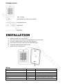
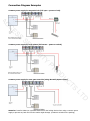
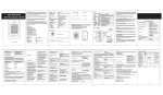
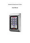
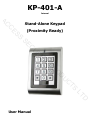
Package contents AC K401-I Keypad C Diode IN4004 (For relay circuit protection) S ES Self Tapping Screws Wall Anchors C SE Screw Driver R U INSTALLATION Remove the back cover from the unit Drill 2 holes (A,C) on the wall for the screws and one hole for the cable Knock the supplied rubber bungs to the screw holes (A,C) Fix the back cover firmly on the wall with 4 flat head screws Thread the cable through the cable hole (B) Attach the unit to the back cover Y IT TS C U D O PR Wire Insulation Colour Function Notes Yellow OPEN Request to Exit input (REX) Red Power + 12-24V DC Regulated Power Input Black GND Ground Blue NO Normally Open Relay Output Purple COM Common Connection for Relay Output Orange NC Normally Closed Relay Output D LT Wiring