1
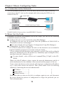
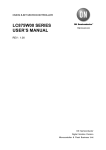
Interface Converter
Instruction Manual
LAN
RS-232C
SI-60F
LAN
RS-232C
SI-60
LAN
RS-422/485
SI-65
The CD-ROM attached to a product contains the newest English and Japanese
instruction manuals in a PDF format. Please also refer to them.
16 th
Introduction
Thank you for your purchase of SI series. To use it correctly,
you are advised to read and understand this instruction manual
thoroughly. Keep this together with the warranty.
Notice
Under the copyright laws, it is prohibited to reprint or duplicate any part or the whole of
this instruction manual without priority from LINEEYE CO., LTD. ("LINEEYE")
All company and product names in this manual are trademarks or registered trademarks of
their respective companies.
The contents of this manual and specifications of the products are subject to change
without notice.
This manual has been designed and edited with great care to give you all information. If
you have any questions, feel free to direct your inquiries to LINEEYE.
LINEEYE makes no warranty or guarantee, either expressed or implied with respect to its
quality, performance, merchantability, or fitness for a particular purpose. LINEEYE shall
not be liable for direct, in-direct, special, incidental, or consequential damages resulting
from any defect in the product. The warranty and remedies set forth above are exclusive
and in lieu of all others.
Copyright © 2010-2013 LINEEYE CO.,LTD. All rights reserved.
1
Safety Information
Be sure to read the following
LINEEYE has developed and manufactured this product for purpose of using with
electrical devices such as a computer, a personal device, a measurement device,
semiconductor manufacturing equipment, a vending machine, a sequencer, display
equipment and so on. LINEEYE does not manufacture this product under the
purpose of using with equipment which may cause malfunction to do harm to the
human body: control equipment for nuclear, aircraft equipment, life maintenance
equipment, traffic signals, etc. Therefore, LINEEYE makes no guarantee with
the mentioned-above use. If you use this product for the purposes mentioned
above, please contact LINEEYE considering safety like Fail Safe under your
responsibilities.
Danger Level
Should the device be used without following these symbols, there
is a possibility of accidents, such as a death or a serious injury,
occurring.
Should the device be used without following these symbols, there
is a possibility of accidents, such as an injury and material damage,
occurring.
*"Injury" indicates injury, burn, an electric shock, or the like which does not
require hospitalization or the extended hospital visit. "Material damage" indicates
damage related to a house, a building, furniture, apparatus, livestock or a pet.
Do not disassemble or modify the converter and AC adapter.
This may cause overheating, a fire, an electric shock, injury or unit malfunction.
Stop using the converter immediately when smoke, smells, or unusual sound emanates
from itself.
Continuous use may cause a burn, fire, or electric shock.
Keep the products dry. Keep them away from water.
Failure to do so may cause overheating, an electric shock, or unit malfunction.
Do not insert the metal scrap or the rubbish such as lead wires into the opening.
Doing so may cause overheating, an electric shock, or unit malfunction.
Never touch the converter and AC adapter with wet hands.
Doing so may cause an electric shock.
Remove the dust on the AC adapter periodically to prevent the heat and ignition.
2
Never use the converter in the place where an inflammable gas leaks.
Doing so may cause ignition.
Do not conduct the installation or wiring work when power is applied.
Doing so may cause an electric shock or unit malfunction.
Do not use the damaged cables.
Doing so may cause fire by overheating.
Use the included AC adapter or ones specified by LINEEYE.
Failure to do so may cause overheating, fire, an electric shock, or injury.
Never touch the converters and cables while thunderbolts are occurring.
Do not connect the power cord to an outlet that has an illegal number of connections.
Doing so may cause fire by overheating.
Do not install the converter in the unstable or vibrating place.
Doing so may cause unit malfunction or injury.
Do not install the converter in any temperature and humid places, or any places which has
the extreme temperature change.
Doing so may cause unit malfunction.
Do not install the converter in any places exposed to direct sunlight.
Doing so may cause a burn or unit malfunction by overheating.
Be sure not to short-circuit the pins on the connector.
Doing so may cause unit malfunction or injury.
Use the included AC adapter with the converter only.
Failure to do so may cause fire or injury by overheating.
Be sure to hold the converter when you disconnect the AC adapter from it.
Failure to do so may cause fire or an electric shock by damaging a cord.
Please do not damage the power cable by pulling, stamping, or tearing.
This may result in a injury, an electric shock, fire, explosion and or a breakdown due to
overheating.
Do not place the cord of the AC adapter near heating equipment.
Doing so may cause fire or an electric shock by melting the cord's cover.
3
■■ Contents ■■
6-3.Set up LAN connection mode...24
6-4. Other Setting.............................25
Chapter 1 Before Using The Product.5
1-1. Overview.....................................5
1-2. Specifications..............................5
1-3. Unpacking and Product
Composition...............................6
1-4. CD-ROM Included.....................6
1-5. Option..........................................6
1-6. Description of I/O pins on the
XPort.........................................6
Chapter 7 Setup Example................. 26
7-1. Server mode usage....................26
7-2. Client Mode Usage...................27
7-3. Using two units of SI-60/65/60F.28
Chapter 8 COM Port Redirector...... 30
8-1.About Virtual COM Port ..........30
8-2. SI60/65/60F Basic Setting........30
8-3. Install COM Port Redirector.....30
8-4. COM Port Redirector Ver4.x.x.x
Setup.........................................31
Chapter2 SI-60F Usage...................... 7
2-1. SI-60F Overview and Features...7
2-2. SI-60F Panel Explanation...........7
2-3. SI-60F Cable Connection...........8
2-4. SI-60F Power Source..................8
2-5. SI-60F Built-in XPort Setup.......8
Chapter 9 Documents....................... 32
9-1. Built in XPort............................32
9-2. Factory Setting..........................33
9-3. How to apply the factory setting.34
9-4. General-purpose I/O pins..........36
9-5. LANConnector Specification ..36
9-6. Installation Method...................37
Chapter3 SI-60 Usage........................ 9
3-1. SI-60 Overview and Features.....9
3-2. SI-60 Panel Explanation...........10
3-3. SI-60 Cable Connection............ 11
3-4. SI-60 Power Source.................. 11
3-5. SI-60 Built-in XPort Setup....... 11
Chapter 10 Warranty and After-Sales
Service....................... 38
Chapter4 SI-65 Usage...................... 12
10-1. Troubleshooting......................38
10-2. Warranty and Repair...............40
10-3. After-Sales Service..................40
4-1. SI-65 Overview and Features...12
4-2. SI-65 Panel Explanation...........13
4-3. SI-65 Hardware Setup...............14
4-4. SI-65 Cable Connection............16
4-5. SI-65 Power Source..................17
4-6. SI-65 Built-in XPort Setup.......17
Chapter 5 Basic Configuring Tasks.. 18
5-1. Connection to the Networok.....18
5-2.Basic Set-Up Tasks ...................18
5-3. IP Address Assignment.............19
5-4. DeviceInstaller Usage...............19
5-5. Check IP Address......................20
5-6. Assign IP Address.....................21
Chapter 6 Configuration Using Web
Manager . ...................... 22
6-1. Web Manager Usage.................22
6-2. Communication conditions of
serial port.................................24
4
Chapter 1 Before Using The Product
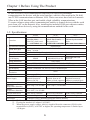
1-1. Overview
SI-60F/SI-60/SI-65 are communication converters to convert asynchronous
communications for devices with the serial interface, which is often used in the FA field,
into TCP/IP communications on Ethernet LAN. These converters have built-in Lantronix
XPort at the LAN interface part, and enable a high- reliability communications.
To create software using socket communications enables to control devices with the serial
ports from a PC on the network. Also, installing the included COM port redirector makes
you control those devices by using the communications method for the serial.
1-2. Specifications
SI-60F
RS-232C
Dsub9 Pin (Male)
#4-40 UNC (inch screw)
DTE fixed
SI-60
SI-65
RS-232C
RS-422/485
5.08mm 6 pole terminal
Dsub25 Pin (Female)
Interface
M2.6 mm Screw
block
DTE/DCE Switchable Able to set the terminator.
S
Asynchronous
e Synchronous Method
r Baud Rate (bps)
300/600/1200/2400/4800/9600/19200/38400/57600/115200/230400/
i
460800 *1/921600 *1
a Data Frame Structure Data (7 or 8) + Parity (Even, Odd or None) + Stop (1 or 2)
l
Flow Control
Xon/off RTS/CTS
Xon/off, Line monitoring
SD,SD/RD,DRIVER
LED Display
SD,RD
SD,RD,RS,CS,(6-20)
ACTIVE
Surge Protection
15KV ESD
Interface
Ethernet IEEE802.3 RJ-45 connector 10BASE-T/100BASE-TX
ARP,TCP/IP,UDP/IP,ICMP,SNMP,TFTP,Telnet,DHCP,BOOTP,HTTP,AutoIP
L Protocol
A LED Display
10BASE-T,100BASE-TX, Activity, Link, Full/Half duplex
N
Transformer
1500V
Insulation
Management
Web manager, Telnet connection, Serial port connection
DC5 to 12V / 300mA
DC5 to 25V/220 to 50mA DC5 to 12V / 250mA
Power Supply
Supplied from an AC
Supplied from an AC
Supplied from an AC
adapter or DC-IN.
adapter or Dsub connector. adapter or terminal block.
3W / 4.4VA*2
3.6W / 5.5VA*2
Power Consumption
1.3W / 3.6VA*2
Operating
*3
-10 to +50 C, 5 to 95%RH -10 to +50 C , 5 to 95%RH
Temperature,Humidity
Storage
-20 to +80 C, 5 to 95%RH
Temperature,Humidity
External Dimension
58(W)×88(D)×24(H)mm
65(W)×95(D)×24(H)mm
65(W)×90(D)×24(H)mm
Weight
170g
200g
200g
Accessories
AC adapter, Utility CD-ROM, Instruction manual, Warranty
*1 SI-60 cannot be used at 460.8Kbps and 921.6Kbps.
*2 If using the attached AC adapter (AC100V).
*3 When the power supply voltage, which is supplied from the connector (SI-60) or the
terminal block (SI-65), is DC10V or higher, the operating temperature is limited up to
+40 degree.
5
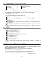
1-3. Unpacking and Product Composition
Make sure of the following when unpacking the product.
Converter
AC Adapter
Utility CD-ROM
:1
:1
:1
Instruction Manual
Warranty
:1
:1
Please let your LINEEYE distributor or LINEEYE know if you find any damage to
the product caused by transportation, or if there are accessories lacking.
1-4. CD-ROM Included
The converter includes the following CD-ROM
The document file such as the instruction manual
Sample program which is helpful to develop software by using the converter
Configuration tool for LINEEYE products embedded XPort /WiPort
(SILANIOinit)
The document files such as the XPort user's manual and XPort Installer issued
by Lantronix.
The utility software for XPort such as COM port redirector issued by Lantronix.
To learn more detail about the contents, read README_E.TXT on the root folder of
CD-ROM.
1-5. Option
We provide the following optional goods.
RS-232C cable(SI-RS259)
RS-422 cable(SI-C422-TT5-5)
RS-485 cable(SI-C485-VT3-5)
Serial / USB Conversion Cable(LE-US232BS)
LAN cable(SI-C5EL-S3)
AUX cable(LE2-8C)
Power plug cable(SIH-2PG)
DIN Plate(SI-DIN70)
For more details about optional goods, please contact LINEEYE distirutors or
LINEEYE.
1-6. Description of I/O pins on the XPort
The XPort embedded on the converter had 3 I/O pins. And the description of the I/O
pins are different by each version of WEB manager. This instruction manual describes
the I/O pins on the XPort as CP0,CP1 and CP2.
Web Manager Ver1.8.0.1: CP0,CP1,CP2:Described in this manual.
Web Manager Ver1.9.0.1:CP1,CP2,CP3.
The version of the XPort differs depending on when you bought the product.
For more information about XPort version, please refer to [ 9-1. Built in XPort ].
6
Chapter2 SI-60F Usage
2-1. SI-60F Overview and Features
SI-60F is a converter to convert asynchronous communications for devices equipped
with the RS-232C interface to TCP/IP or UDP/IP communications on Ethernet LAN.
It connects RS-232C interface device to a PC without a serial port via LAN, with a
small DTE(fixed) Dsub9 pin (male).
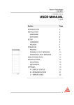
2-2. SI-60F Panel Explanation
88
24
2
58
1 Power LED
2 Data Status LED
3 AC Adapter Jack
4 Ethernet Connector
5 RS-232C Connector
Lights when turning on the power.
Indicates the data transmission/ reception status for RS-232C.Lights
when the pin signal corresponding to Dsub connector is above +3V.
Is a socket to connect to the AC adapter.
[ 2-4. SI-60F Power Source]
Ethernet IEEE802.3 RJ-45connector 10Base-T/100Base-TX autodetection available.
[ 9-5. LAN Connector Specification ]
Dsub9 pin (male) Screw: #4-40 UNC(inch screw)
Block Chart
RS-232C Connector Pin Assignment
Pin Name
No.
1
CD
2
RD
3
SD
4
ER
I/O Direction
Description
In
Out
non-connected
Reception Data
Transmission Data
Internal connection to 6
pin *2
Signal Grand
Internal connection to 4
pin *2
Transmission Request
Transmission Permit
non-connected
*1
In
5
GND
-
6
DR
In
7
8
9
RS
CS
CI
Out
In
-
*1 "Out" means a direction to output signals from the converter.
"In" means a direction to input signals to the converter.
*2 Inputs the negated signals to the CP1 terminal on a built-in XPort.
7
2-3. SI-60F Cable Connection
LAN
Connect by the proper UTP cable to the LAN connector.
For 10Base-T ------------------- Category 3, 4, 5
For 100Base-TX --------------- Category 5
Note: Although the standardized length of a LAN cable is max. 100 meters, use the
cable as short as possible if there is much noise.
[ 5-1. Connection to the Networok ]
RS-232C
Connect by the proper RS-232C cable which fits the shape of the RS-232C connector
on the target devices. Then, make sure of the input/output specification of signal pins.
e.g.1: Connecting the serial port (Dsub9 pin - male) of SI-60F to the device (Dsub25
pin, female) of DCE specification.
Use straight connection cable such as SI-RS259(SI-RS259 cable is an
optional cable.) to connect.
e.g.2: Connecting the serial port (Dsub9 pin - male) of SI-60F to the device
(DSUB9pin, male) of DCE specification.(male)
Use cross connection cable which both ends with DSUB9pin(female) to
connect.
e.g.3: Connecting the AUX port (Mini DIN8 pin, female) of analyzers, (LE-8200/35
00/2500/7200/3200/2200/1200) to SI-60F.
Use LE2-8V cable to connect.(LE2-8V cable is an optional cable.)
2-4. SI-60F Power Source
Supply power to the converter in either of two ways.
Supplies power by plugging the included AC adapter or the optional AC
adapter into the AC adapter plug. The AC adapter of Japanese model is for the
use in Japan only.
Supply DC5V to 12V (4W) from 9pin of RS-232C connector.
Note: Do not connect an AC adapter when supplying from RS-232C connector.
Connection Plug: Outer diameter is 5.5mm. Inner diameter is 2.1mm.
Length of top of the plug is 9.5+0.3mm. (Possible to use both center plus
and center minus plug.)
2-5. SI-60F Built-in XPort Setup
Depending on the network environments or the usage, the built-in XPort setup of the
converter is required to change. To learn about XPort setup, read [Chapter 5 Basic
Configuring Tasks][Chapter 6 Configuration Using Web Manager ].In addition, when
using the COM port redirector, read [Chapter 8 COM Port Redirector].
8
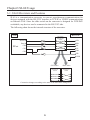
Chapter3 SI-60 Usage
3-1. SI-60 Overview and Features
SI-60 is a communication converter to convert asynchronous communications for
devices equipped with the RS-232C interface to TCP/IP or UDP/IP communications
on Ethernet LAN. Since the slide switch on the converter is designed for DTE/DCE
switchable, any devices can be connected to the RS-232C side.
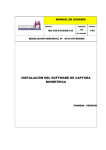
The following chart shows the internal structure of the converter.
LAN
DTE/DCE
changeover
switch
Data Out
XPort
RS-232C
SD
Data In
RD
CP 0
RS
CS
DR
CP 1
CP 2
ER
GND
<DTE side>
<DCE side>
DTE/DCE
changeover
switch
DTE/DCE
changeover
switch
Connection changes according to the state of the DTE/DCE changeover.
9
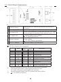
3-2. SI-60 Panel Explanation
95
24
2
65
1 DTE/DCE Switch
2 Power Supply LED
3 Data Status LED
4 AC Adapter Jack
5 Ethernet Connector
6 RS-232C Connector
Changes the RS-232C connector specification of the converter to
DTE or DCE.
Lights when powering the converter.
Indicates a data transmission/ reception status for the RS-232C.Lights
when the pin signal corresponding to Dsub connector is above +3V.
Is a socket to connect to the AC adapter.
[ 3-4. SI-60 Power Source ]
Ethernet IEEE802.3 RJ-45connector 10Base-T/100Base-TX autodetection available.
[ 9-5. LAN Connector Specification ]
Dsub25 pin (Female) M2.6 mm Screw
RS-232C Connector Pin Assignment
Pin No.
*1
*2
*3
*4
*1
Name
1
2
3
4
5
6
7
9
20
FG
SD
RD
RS
CS
DR
GND
+DC IN
ER
I/O Direction *2
DTE
DCE
Out
In
In
Out
Out
In
In
Out
In
In
In
In
Description
Frame Grand
Transmission Data
Reception Data
Transmission Request
Transmission Permit
Internal connection to 20 pin*3
Signal Grand
External power supply input *4
Internal connection to 6 pin *3
Pins not mentioned in this table indicate the non-connected terminals.
"Out" means a direction to output signals from the converter.
"In" means a direction to input signals to the converter.
Inputs the negated signals to the CP1 terminal on a built-in XPort.
[ 3-4. SI-60 Power Source]
10
3-3. SI-60 Cable Connection
LAN
Connect by the proper UTP category cable which matches the Ethernet connector.
For 10Base-T ------------------- Category 3, 4, 5
For 100Base-TX --------------- Category 5
Note: Although the standardized length of a LAN cable is max. 100 meters, use the cable as
short as possible if there is much noise.
[ 5-1. Connection to the Networok ]
RS-232C
Connect with the proper RS-232C cable which fits the shape of the RS-232C connector
on the target devices. Then, make sure of the input/output specification of signal pins and
connection of the RS-232C cable. Set DTE/DCE switch.
e.g.1: Use straight connection cable to connect the device which has DCE specifications.
Set DTE/DCE switch to DTE.
e.g.2: Use SI-RS259 cable to connect the PC(DTE).
Set DTE/DCE switch to DCE.
e.g.3: Use LE2-8V cable to connect the AUX port (Mini DIN8 pin, female) of analyzers,
(LE-8200/3500/2500/7200/3200/2200/1200) to SI-60.
Set DTE/DCE switch to DTE.
3-4. SI-60 Power Source
Supply power to the converter in either of two ways.
Supplies power by plugging the included AC adapter or the optional AC adapter into
the AC adapter plug. The AC adapter of Japanese model is for the use in Japan only.
Supply DC5V to 12V (4W) from 9pin of RS-232C connector.
Note: Do not connect an AC adapter when supplying from RS-232C connector.
Connection Plug: Outer diameter is 5.5mm. Inner diameter is 2.1mm.
Length of top of the plug is 9.5+0.3mm. (Possible to use both center plus
and center minus plug.)
3-5. SI-60 Built-in XPort Setup
Depending on network environments or the usage, the built-in XPort setup of the converter is
required to change. To learn about XPort setup, read "XPort Setup" in Chapter 5 and [Chapter
6 Configuration Using Web Manager].
In addition, when using the COM port redirector, read "COM Port Redirector" in Chapter 8.
11
Chapter4 SI-65 Usage
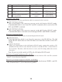
4-1. SI-65 Overview and Features
SI-65 is a communication converter to convert asynchronous communications for
devices equipped with the RS-422/485 interface to TCP/IP communications on Ethernet
LAN. Since the converter supports both two-wire and four-wire full duplex, using the
device allows you to support various systems.
The following chart shows the internal structure of the converter.
Line Monitoring Function
RS-485 communications of two-wire half duplex is required to send data after
confirming that any devices have not sent data into the RS-485 line. The line monitoring
function allows to detect that any devices have not sent data into the RS-485 line, and
to conduct the flow control. To use this function, the flow control of built-in XPort is
required to set to CTS/RTS (Hardware).
RS-485 Line Condition
The period of time from when to detect a space bit of the
data in the RS-485 line sent by another device, to when
not to get to continuously detect a space bit over internal
timer time of the converter, while the RS-485 driver of the
converter is not active.
The period of time when not to detect a space bit in the
RS-485 line which another device continuously sends over
internal timer time of the converter, or when the RS-485
driver of the converter is active.
Flow Control Condition
Prohibits sending data
from the converter to
the RS-485 circuit.
Permits to send data
from the converter to
the RS-485 circuit.
Note: This function allows the flow control to operate in a direction of sending only.
The flow control in a direction of receiving does not operate.
12
4-2. SI-65 Panel Explanation
90
24
2
65
1 Power Supply LED
3 Driver Status LED
Lights when turning on the power.
Indicates a data transmission/ reception status for RS-422/485.Blinks the
SD LED if there is data from LAN to RS-422/485. Blinks the RD LED if
there is data from RS-422/485 to LAN.
Lights when the driver for RS-485 is active.
4 Dip Switch A *1
Selects the line monitoring function and driver control.
2 Data Status LED
5 Dip Switch B *1
6 AC Adapter Jack
Selects the communication method, terminator, etc.
Is a socket to connect to the AC adapter.
[ 4-5. SI-65 Power Source ]
Ethernet IEEE802.3 RJ-45 connector. 10Base-T/100Base-TX auto-detection
7 Ethernet Connector
available.
[ 9-5. LAN Connector Specification ]
RS-422/485 Terminal 5.08mm pitch 6pole terminal block (Press-to-screw type) Standard Torque:
8
Block
0.25Nm/M3.
[ 4-4.SI-65 cable connection ]
*1 Press down the DIP switch to switch on and
press up to switch off.
6 Pole Terminal Block Pin Assignment for RS-422/485
Full Duplex Mode *1
I/O Direction*2
Description
Out
Transmission Data+
Out
Transmission Data-
Terminal
No.
Name
1
2
SD+
SD-
3
SD/RD+
In
Reception Data +
4
SD/RD-
In
Reception Data -
5
GND
-
Signal Grand *4
6
+5V IN
-
External Power Input *5
Half Duplex Mode *1
I/O Direction*2
Description
Cannot use *3
Cannot use *3
Transmission/
I/O
Reception Data +
Transmission/
I/O
Reception Data Signal Grand *4
External Power
Input *5
*1 Can switch by the dip switch.
*2 "Out" means a direction to output signals from the converter. "In" means a direction to
input signals to the converter. "I/O" means both directions to input and output.
*3 Do not connect anything when using the half duplex mode.
[ 4-4. SI-65 Cable
*4 Connect GND to prevent devices from over voltage damage.
Connection ]
*5
[ 4-5. SI-65 Power Source ]
13
4-3. SI-65 Hardware Setup
The two 4-position dip switches on the converter allows you to conduct the following
setups: the line monitoring function, the driver control method, terminator enable/disable,
and echo back enable/disable.
SW-A No.1-3 (Baud Rate Setup)
Following communication speed (baud rate) you wish to use, this setup is to set the
internal timer used for the non-communication monitoring circuit and driver control
circuit. Using this timer conducts to monitoring non-communication condition more than
16 bits in RS-485 line and to control the RS-485 driver.
* Speed
[ 6-2. Communication conditions of serial port]
Speed (bps)
[ ] indicates a representative
example.
Over300 [300, 600]
Over 1200 [1200]
Over 2400 [2400]
Over 4800 [4800]
Over 9600 [9600]
Over 19200 [19200]
Over 38400 [38400, 57600]
Over 115.2k [115.2k to 920k]
SW-A No.1 SW-A No.2 SW-A No.3
OFF
ON
OFF
ON
OFF
ON
OFF
ON
OFF
OFF
ON
ON
OFF
OFF
ON
ON
OFF
OFF
OFF
OFF
ON
ON
ON
ON
Internal Timer *1(ms)
57
14.3
7.1
3.6
1.8
0.9
0.45
0.11
*1 The internal timer is accurate at +10 to -10%.
SW-A No.4 (Driver Control)
Selects two kinds of control methods in the RS-422/485 driver control line of the
converter: active and auto.
SW-A
No.4
Meaning
RS-422/485 transmission driver control
OFF
Active
ON
Auto
OFF (Active) Setting
To keep the driver active, set the CP1 of the XPort I/O pin "L"(active). ("H" is for non-active.)
[ 9-4. General-purpose I/O pins]
The default setting of CP1 is a low level.
ON (Auto) Setting
This setting detects the first space bit (start bit) in the string which you wish to send
from the converter to the RS-422/485 line, and automatically makes the driver active.
The active status of the driver keeps from the last space bit in the string being sent until
the internal timer time being set. After that, the driver automatically becomes nonactive.
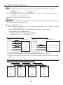
<eg.>9600bps Data 31H SW-A No.1-3 OFF/OFF/ON (1.8mS)
The following chart shows the driver control of the converter.
Mark
Data
Space
Driver On
Controll Off
1 0 1 0 0 0 1 1 0 0 1
start b0 b1 b2 b3
bit (LSB)
b4 b5
b6 b7 stop
(MSB) bit
Idle
Inner Timer(1.8ms)
Driver Active
The device is kept active for 1.8ms (internal timer time) after the last space bit.Please
do not let the other device respond within 1.8ms.
14
SW-B
Meaning
No.1 Select a line mode
No.2 Echo reception of transmission
data
No.3 Terminal control between SD+
and SDNo.4 Terminal control between SD/
RD+ and SD/RD-.
OFF
RS-422 (full duplex)
With echo back
ON
RS-485(half duplex)
Without echo back
Without terminal
control
Without terminal
control
With terminal
control(100 ohm)
With terminal
control(100 ohm)
SW-B No1 (Line Mode)
Selects the RS-422/485 line specification which is connected to the converter.
OFF (Full Duplex) Setting
This setting makes the converter operate in the full duplex RS-422 mode.
Communicated data is sent from SD+ and SD- terminals, and is received to SD/
RD+ and SD/RD- terminals.
ON (Half Duplex) Setting
This setting makes the converter operate in the half duplex RS-485 mode.
Communicated data is sent and received through SD/RD+ and SD/RD- terminals.
SW-B No.2 (Echo Back Setup)
Selects the echo back specification for the half duplex RS-485 mode.
OFF(Echo Back)
Echo back the data which is sent from the converter to the RS-485 line. The full
duplex RS-422 mode does not echo back data even when this switch is in the OFF
setting.
ON(No Echo Back)
When you communicate in the half duplex RS-485 mode, setting this switch to ON
prohibits the data, which is sent from the converter to the RS-485 line, is echoed back to
the LAN host. Therefore, while the driver is active, the ON setting makes the receiver
non-active.
Note: Be sure to set this switch to OFF in the full duplex RS-422 mode.
SW-B No.3 (Terminal End Between SD+ and SD-)
Setting this switch to ON inserts the terminator 100 ohm between SD+ and SD- (terminal
block 1, 2) in a direction of parallel.
SW-B No.4 (Terminal End Between SD/RD+ and SD/RD-)
Setting this switch to ON inserts the terminator 100 ohm between SD/RD+ and SD/
RD- (terminal block 3, 4) in a direction of parallel.
15
4-4. SI-65 Cable Connection
LAN
Connect by the proper UTP category cable which matches the Ethernet connector.
For 10Base-T ------------------- Category 3, 4, 5
For 100Base-TX --------------- Category 5
Note: Although the standardized length of a LAN cable is a maximum 100 meter, use
the cable as short as possible.
[ 5-1. Connection to the Networok ]
RS-422/485
Connect RS-422/485 terminal block of SI-65 and RS-422/485 signal line of the target
device by using a twisted pair cable.
Proper RS-232C cable
Size : AWG24-14, single wire 0.2- 2.5mm2, twisted cable 0.12- 1.5mm2, L=6mm
can be removed.
If using the ferrule terminal, ferrule diameter should be 1.5mm or less.
Following are the recommendation.
Phoenix Contact Inc. "AI0.25-8YE AWG24"
JST Mfg. Co., Ltd." TUB-05 AWG26-22"
RS-422 (full duplex) Setting
SI-65
SD+
RS-485(half duplex) Setting
Target Device
SI-65
Receive+ (RDB)
SD+
SD-
Receive- (RDA)
SD-
Target Device
SD/RD+
Send+ (SDB)
SD/RD+
Send and Recive + (DataB)
SD/RD-
Send- (SDA)
SD/RD-
Send and Recive - (DataA)
GND
GND
GND
GND (SG)
(SG)
* ( ) are the examples of RS-422/485 differential signals.
Usually, differential signal [+] uses [B] and differential signal [-] uses [A].
* Connect the GND(SG) between devices to protect higher voltage runs into the other
device.
The following chart shows a connection example to connect the converter to more than
two devices in the half duplex mode by N to N.
SI-65
Nth Unit
GND
16
SD/RD SD/RD +
SD SD +
SI-65
3rd Unit
GND
SD/RD SD/RD +
SD SD +
SI-65
2nd Unit
GND
SD/RD SD/RD +
SD SD +
GND
SD/RD SD/RD +
SD SD +
SI-65
1st Unit
<Transfer Distance>
The faster communication speed is, the shorter the
transfer distance for RS-422/485 is. See the right table
and set communication speed following the actual
distance.
Also, the maximum of the actual communication
speed changes depending on conditions: environments
like noise, cable features used, etc. For actual use, be
sure to conduct a communication test to check.
Distance (m)
100
200
600
1200
2400
Speed (bps)
to 920k
to 230.4k
to 115.2k
to 57.6k
to 9,600
4-5. SI-65 Power Source
Supply power to the converter in either of two ways.
AC adapter
Supplies power by plugging the included AC adapter or the optional AC adapter
into the AC adapter plug on the converter. The AC adapter of Japanese model is
for the use in Japan only. Please do not exceed the input voltage rate. To use the
products abroad, an optional AC adapter is available.
Connection Plug: Outer diameter is 5.5mm. Inner diameter is 2.1mm. Length
of top of the plug is 9.5+0.3mm. (Possible to use both center plus and center
minus plug.)
Terminal block
Supplies DC+5 to +12V (4W) from 6 pin of 6 pole terminal block.
4-6. SI-65 Built-in XPort Setup
Depending on network environments used or the usage, built-in XPort setup of the
converter is required to change. To learn about XPort setup, read [Chapter 5 Basic
Configuring Tasks ]and [Chapter 6 Configuration Using Web Manager ]
In addition, when using the COM port redirector, read [ Chapter 8 COM Port
Redirector]
17
Chapter 5 Basic Configuring Tasks
5-1. Connection to the Networok
To set the products from the PC via LAN cable, use the cross cable for directly
connecting to the PC. And, use the straight cable when using the HUB (etc.) to
connect to the PC.
LAN Cable
SI-60F/SI-60/SI-65
HUB
LAN Cable(Cross Cable)
SI-60F/SI-60/SI-65
*SI-60F/SI-60/SI-65 does not have AutoMDI/MDI-X Function.
5-2.Basic Set-Up Tasks
Depending on network environments used or the usage, you can use the following
procedures remotely or locally:
Configure the unit over the network by using Web Manager
To configure the unit over the network, enter the IpAddress of SI60/65/60F to
Web browser and use web manager.
For more details refer to [Chapter 6 Configuration Using Web Manager ]
Configuration via Telnet or Serial Port
Use a Telnet connection to configure the unit over the network or use a terminal or
terminal emulation program to access the serial port locally.
( IF you configure the unit through a serial connection, reset the XPort unit by cycling the
unit's power (turning the power off and back on). Immediately upon resetting the device,
enter three lowercase x characters (xxx).)
For more details , refer to XPort user’s manual(XPort_UG.pdf ) in the CDROM.
When you allot IP address, please contact the network administrator and do it
with consideration for the condition of the network and the purpose of the use.
If you connect the devise to the network with improper configuration (IP address
e.g.), it may affect whole the network. Thus, please make a note of following
contents by contacting the network administrator.
IP Address .....................[
.
.
.
]
Subnet Mask..................[
.
.
.
]
Default Gateway............[
.
.
.
]
Please note that you may not be able to configure again in case you disconnect
the power during the process of configuration or forget the password you set.
This will need repair.
18
5-3. IP Address Assignment
Before using the converter, you need to assign IP address to the built-in XPort.
There are some IP address assignment methods. Assign by the proper method,
concerning the usage and environments, and consulting with your network manager.
* When the configuration of the IP Address of XPort (built-in) is 0.0.0.0 (factory
setting), these functions will be Enable. In case of 0.0.1.0, only the DHCP Client
function will be Enable.
Using the DHCP Function
When the DHCP function is valid, XPort receives IP address, subnet mask and
default gateway address, which were dynamically assigned by DHCP server on the
network, at the time of starting XPort operation.
Using the AutoIP Function
When AutoIP function is valid and there is no DHCP server on the network, XPort
selects an IP address within the class B subnet 169.254.x.x, at the time of starting
XPort operation. And it uses the ARP request to check whether or not any devices
on the network use the address.
If it is not used, the address will be used as the XPort address. If it is used, XPort
selects another IP address from the reserved addresses, and check it again by the
ARP request.
[ 5-4.DeviceInstaller Usage] [ 9-1. Built in XPort ]
5-4. DeviceInstaller Usage
The CD-ROM contains a utility "Device Installer" to assign the IP address.
"Microsoft .NET Framework 2.0" or ".NET Framework 4.0" are needed for some
version of the Device Installer.
Note
When you use this device concurrently with a device which has XPort of
older firmware (v1.8 or older), please use the DeviceInstaller which was used
for the device of the older firmware.
In this case, XPort device of the current firmware will be shown as
"(Unknown:x9)".
To install, login to a PC in administrator rights and follow the installation wizard
instructions.
1. Execute the setup file in the DeviceInstaller. Select the folder which matches
your version. (*1)
2. Follow the installation wizard instructions.
19
3. After Installing the DeviceInstaller, following page will be appeared. Select "No".
This message on the screen is to prompt you to update the PIB file which relates
a device ID of Lantronix products to the device name.
You need not update if you are using Deviceinstaller of the latest version. But if
you are using Ver4.1.x.x or older, please update it from the website of Lantronix
because the XPort-05 will be shown as "Unknown X9".
* 1 : The version of the DeviceInstaller may differ depending on when you
bought this product. Please refer Release.txt in the folder of the name of
the version in the CD-ROM attached to the product (CD-ROM\lantronix\
DeviceInstaller\) for the detail of .Net Framework and supported OSs.
5-5. Check IP Address
1. Connect SI60/65/60F to the network.
2. Start Device Installer from the start menu.
3. The main window of Device Installer appears.It finds SI-60F/SI-60/SI-65
connected to the network automatically and lists in a table on the main window. (If
there are devices other than SI-60F/SI-60/SI-65 using XPort on the network, they
are also listed in a table..)
4. Select which matches the hardware address for the device being set from the table.
20
5-6. Assign IP Address
1. On the toolbar, click Assign IP . The Assign IP Address window displays.
2.On the Assignment Method page, select Assign a specific IP address and click
[Next].
Obtain an IP address
automatically
Assign a specific IP
address
[ Assign a specific IP address ]
3."IP Settings" page appears. Enter
the values. Then click [Next] .
[ Obtain an IP address automatically ]
3."IP Discovery Settings" page appears.
Select a function you would like to
enable, and then click [Next].
* Assign by the proper method, concerning the usage and environments, and
consulting with your network manager.
* We recommend you to disable DHCP and BOOTP or always keep Auto-IP
effective because when failing in the address assignment, Device Installer
cannot detect SI-60F/SI-60/SI-65 even if DHCP, BOOTP or both are effective.
4. XPort restart by pressing "Assign" button on the "Assignment" page.
IP address can also be assigned using Setup mode and SILANIOinit.
Reffer to XPort user’s manual(XPort_UG.pdf ) in the CD-ROM.
SILANIOinit is configuration tool for LINEEYE products embedded XPort/
WiPort.
21
Chapter 6 Configuration Using Web Manager
6-1. Web Manager Usage
The configuration can be changed from a Web manager(Lantronix’s browser-based
configuration tool).
For more details refer to XPort user’s manual(XPort_UG.pdf ) in tne CD-ROM.
Accessing from the deviceinstaller
Start DeviceInstaller from the start menu to display DeviceInstaller window.Select
] icon. Enter
the device being set. Select “Web Configuration” tab and click [
the user name and the password, as you will be required. If you have not set your
user name and password, enter nothing and click “OK”.
Accessing from the web browser
Open your web browser and enter the IP address of the XPort(IP address of SI60/65/60F) Then you will be required to enter the user name and the password. If
you have not set your user name and password, enter nothing and click “OK”.
22
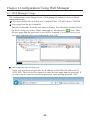
Web Manager Usage
Server setting such as CPU Performance
Serial Commnunication Conditions setting
LAN Connection setting.
After setting the various settings such as [Port Settings] ,[Connection] etc.., click
“OK” button. Then“Done!” will be displayed and the setup contents hold by Web
Manager temporarily.
To save and apply the configuration changes to the device server, click the Apply
Settings button.( Clicking OK on each page does not change the configuration on
the device. Clicking the OK button tells the XPort what changes to use; the Apply
Settings button makes the changes permanent and reboots the XPort.)
Note
Set the setting of IE. Select [Tool]
[Internet Options]
[Temporary Internet
files] and set as [Every visit to the page]
When you use Internet Explorer10, please use it in compatibility mode.
Note: If you change the IP address or the default gateway and set it by “Apply
Setting”, state of progress of configuration process will appear repeatedly,
because the connection between this device and the PC for configuration
cannot be sustained.
In this case, please close the Web manager. Then run the Web manager again
with the changed IP address.
23
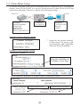
6-2. Communication conditions of serial port
1.When using SI-60F/SI-65 with baud rate 460800/921600bps of the serial port,
select "Server" and set High to "CPU Performance Mode". Then, set baud rate of
"Serial Settings".
2.Select [Channel1 ] -> [Serial Settings].
Set “Protocol” to be “RS-232C”in serial side. Set Baud Rate, Data Bits, Parity,
Stop Bits and Flow Control to be same as the target device.
3. Click[ OK ] and then click [ Apply Settings ].
6-3.Set up LAN connection mode
LAN protocol
Select [ Channel 1 ] --> [ Connection ].Then select TCP or UDP.
You can setup either one of them.
* IF you select UDP protocol, set [ Datagram Type ] to [ 01 ].
Change [ Remote Host ] and [ Remote Port ] if necessary.
Server Mode
If you select TCP protocol set [ Accept Incoming ].
Select Yes to accept incoming connections.(Server mode)
Client Mode
If you select TCP protocol set [ Accept Incoming ].
Select No to Never accept incoming.(Client mode)
24
6-4. Other Setting
For more details , refer to the online help or XPort user’s manual (XPort_UG.pdf)] in
the CD-ROM.
Pack Control
The packing algorithms define how and when packets are sent to the network.
Select [ Channel 1 ] -->[ Serial Settings ] and check [ Pack Control ]--> [ Enable Packing ]
to control the received data as you define.
e.g.)
Packets are sent to the network, when no serial data is received for 12
msecs or received 2bytes of CRC data after received 0x03
Idle Gap Time
Match 2 Byte Sequence
Match Bytes
Send Frame Immediate
Send Trailing Bytes : Two
: 12msec
: No
: 0x03,0x00
: No
If the packet size reaches to the Maximum Transmission Unit(MTU)(default
1400 bytes), a transmission might occur even if the packets are not satisfy
the condition.
Disconnect TCP
Select [ Channel 1 ] -> [ Connection ] and set [ Disconnect Mode ] to setup the condition of
disconecct TCP by the serial non-communication time.
TCP Keepalive
Select [ Server ].Set [ TCP Keepalive (secs) ]1 to 65(sec).
No TCP keepalive packet will be send, if you set 0.
Check the connection status by sending the TCP packet for checking.
Restore default XPort settings
Select [ Apply Defaults ] of Main menu to initial (factory default) all setup, except network
address(such as IP address etc.) and I/O pin.
[9-2. Factory Setting]
25
Chapter 7 Setup Example
7-1. Server mode usage
To use Device A (connected with the serial port of SI-60/65/60F) through network
connection by TCP connection request from a device on the network such as PC to
SI-60/65/60F, please refer following setting.
PC
LAN
Serial
IP Address:
192.168.0.60
Example of DeviceInstaller Setting
Device
A
Condition :
Speed 38400bps,
Length 8bit,
Parity None,
Stop bit 1bit,
Flow control Xon/Xoff
* Assign by the proper method, concerning the usage and environments, and
consulting with your network manager.
Example of Web Manager Setting
Serial port communication condition
Connect Mode(Sever mode:Yes, Client Mode: None)
26
7-2. Client Mode Usage
To use the serial port of the Device A through network connection by TCP connection
request from SI-60/65/60F to a server on the network when SI-60/65/60F has
received a serial data of Device A, please refer following setting.
Device A
Server
LAN
Serial
Condition :
Speed 921600bps,
Length 8bit,
Parity even,
Stop bit 1bit,
Flow Control RTS/CTS
IPAddress:
192.168.0.61
IPAddress:
192.168.0.100
Port No.
10005
Example of DeviceInstaller Setting
* Assign by the proper method,
concerning the usage and
environments, and consulting
with your network manager.
Example of Web Manager Setting
SerialPort Condition
If Speed is 460800bps or
921600bps. Select High
LANConnection Mode(Server Mode:Disable,ClientMode:Enable)
Remote HostPort No.
27
Remote Host IP Address
7-3. Using two units of SI-60/65/60F
To extend serial communication between Device A and Device B through network by
using two units of SI-60/65/60F, please refer following setting.
Device A
Device B
LAN
Serial
Condition:
Speed 115200bps,
Length 8bit,
Parity even,
Stop bit 1bit,
Flow Control RTS/CTS
Serial
SI60/65/60F 1
IPAddress :
192.168.0.60
Port No.
10001
Example of DeviceInstaller Setting
SI60/65/60F 1
SI60/65/60F 2
IPAddress :
192.168.0.61
Port No.
10001
Condition:
Speed 9600bps,
Length 8bit,
Parity even,
Stop bit 1bit,
Flow Control RTS/CTS
SI60/65/60F 2
* Assign by the proper method, concerning the usage and environments, and
consulting with your network manager.
Example of Web Manager Setting
SerialPort Condition
SI60/65/60F 1 ( 9600bps Pack Control Enable)
Algorithms define how and when
packets are sent to the network.
* This is only an exsample.
SI60/65/60F 2( 115200bps Pack Control Disable)
The standard algorithm is optimized for
applications in which the unit is used
in a local environment, allowing for
very small delays for single characters,
while keeping the packet count low.
28
LANConnection Mode
SI60/65/60F 1(Server Mode: Enable,ClientMode:Enable)
Remote
Host2
Remote
Host2
Port No.
IPAddress
SI60/65/60F 2(Server Mode: Enable,ClientMode:Enable)
Remote
Host1
Remote
Host1
Port No.
IPAddress
Because "Active Connect" of both SI-60/65/60F 1 and SI-60/65/60F 2 are
configured as "With Any Character", when a serial port of SI-60/65/60F 1 or
2 receives data, the device which received the data will connect with the other
device by TCP and send the data through the network.
Note: Like this example, communication will be done without errors though the
conditions of Device A and Device B differ. However, please confirm that this
time gap of send/receive or any other effect of this function will not affect the
system before the usage.
29
Chapter 8 COM Port Redirector
8-1.About Virtual COM Port
The COM Port Redirector is the utility software to get the serial communication
application not supporting the network connection to be able to use on the network.
The redirector creates the virtual COM ports in Windows. Communications for these
virtual COM ports are transferred to the serial port on the converter through the
network.
Note
The COM Port Redirector works at most of the application software. However,
some applications, which have a limit to receive/transmit data, may not work
well. In this case, change the timeout of communication longer or change the
setting to support socket communications.
The COM Port Redirector cannot be used with other software, which creates
the virtual COM port. Be sure not to install the COM Port Redirector to PCs,
which have already installed such software.
8-2. SI60/65/60F Basic Setting
Depending on the target devices, setup of the serial port and virtual COM port
condition is required to change.
[ 6-2. Communication conditions of serial port ]
Assign a specific IP Address.(recomendation)
[ Chapter 5 Basic Configuring Tasks ]
8-3. Install COM Port Redirector
Install ComPortRedirector(SPR) to your PC.
* If you already have other version of COM Port Redirector, please uninstall it.
* Login to the PC as administrator.
1.Insert the utility CD-ROM into the CD-ROM drive.Select Execute the setup file in
the ComPortRedirector. Select the folder which matches your version.
2.To install, follow the installation wizard instructions.
3.Restart the PC.
NOTE: Environment for the usage of supported OS differs depending on the version
of the ComPortRedirector attached to the product. For further detail,
please refer Release.txt in the folder of the name of the version (\lantronix\
ComPortRedirector) in the CD-ROM attached to the product.
30
8-4. COM Port Redirector Ver4.x.x.x Setup
Connect SI60/65/60F to the network.
Login to the PC as administrator.
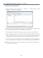
1. From start menu, go to "Lantronix" -> "CPR 4.x" -> "CPR Manager. "CPR
Manager" window will be displayed.
2.Click [Com Port]-[Add and Remove] of toolbar to open the dialog to register/delete
the virtual COM port. Select the COM number and click [OK].
3. In the dialog box, check the COM port you wish to use as the virtual COM port.
4. In the [ Settings ] tab, there is a host list table. Set the IP address and port number at [
Host ] and [ TCP Port ] in the [ Service1 ]. Click [ Search For Devices ] icon and
double clicking the XPort on the “Device list” to reflect it in the host list table.
5. Click “Save” icon or go to [Com Port] -> [Save Settings] to save the configurations.
If your computer shows a dialog of hardware installation, ignore it and click [Next].
For more details , refer to Com Port Redirector manual(Com-Port-Redirector_
QS.pdf) in the CD-ROM
31
Chapter 9 Documents
9-1. Built in XPort
XPort is built in SI60/65/60F and it is the lan communication module of Lantronix.
Web Manager
Web-Manager is Lantronix’s browser-based configuration tool to configure the
XPort.
For more details , refer to [Chapter 6 Configuration Using Web Manager ]
DHCP Client Function and AutoIP Function
Before using the converter, you need to assign IP address to the built-in XPort.
There are some IP address assignment methods. Assign by the proper method,
concerning the usage and environments, and consulting with your network
manager.
[ DHCP Client Function ]
When the DHCP function is valid, XPort receives IP address, subnet mask and
default gateway address, which were dynamically assigned by DHCP server on
the network, at the time of starting XPort operation.
[ AutoIP Function ]
When AutoIP function is valid and there is no DHCP server on the network,
XPort selects an IP address within the class B subnet 169.254.x.x, at the time of
starting XPort operation. And it uses the ARP request to check whether or not any
devices on the network use the address.
Version and Other information
The XPort has been updated several times. To use this product properly, please
use the manual and the tools contained in the CD-ROM, which comes with the
product.
Model
Shipment
Hardware
Firmware
60/65/60F
Since 2009
Since 2010
Since 2013
Since 2013
XPort-03
XPort-04
XPort-04
XPort-05
6.6.0.2
6.7.0.1
6.8.0.2
6.9.0.2
WEB
Manager
1.7.0.1
1.8.0.1
1.9.0.1
2.0.0.2
CPR
4.2.0.0
4.3.0.0
4.3.0.1
4.3.0.3
Confirm the firmware version in the property of device, which is searched and
shown by Device Installer.
For more details refer to the HP of Lantronix(http://www.lantronix.com).
32
About XPort-05
The XPort which is built in the product has been changed from XPort-04 to
XPort-05 because of the version-up by the manufacturer.
You can use this product as before because the product specification of this
device has not been changed and there is no problem in using with conventional
products.
<Changed content of the XPort>
MAC address (vendor code) has been changed to “0080A3”.
No compatibility with the firmwares of XPort-03/04.
The design of the top page of the Web manager has been changed.
9-2. Factory Setting
When SI60/65/60F is shipped, built-in XPort are set as follows :
RS-232C Condition:
Protocol: RS232 ( Do not change),
Speed : 9600bps , 8bit, Parity: None , Stop 1bit, Flow Control: None
LAN Action Mode:
Accept Incoming Yes(Server ModeEnable),
Active Connect None(ClientModeDisable),
Port No.10001,
IP Address0.0.0.0 (DHCP Client Function and AutoIP Function : Enable)
Telnet password:
(Password : Disable)
Configurable Pins:
Item
CP0
CP1
CP2
Active
Level
SI-60F
HW Flow Control out
General Purpose I/O
(Input)
HW Flow Control In
Setting Values
SI-60
HW Flow Control out
General Purpose I/O
(Input)
HW Flow Control In
SI-65
HW Flow Control out
General Purpose I/O
(Output)
HW Flow Control In
Low
Low
High
Note: Do not change the settings of CO1 and Active Level.
Webmanager for XPort firmware v1.8 displays “CP1” for “CP0”, “CP2” for “CP1”
and “CP3” for “CP2”.
[1-6. Description of I/O pins on the XPort]
Items excepting Configurable Pins have the same setups with the factory default for
XPort.
For more details refer to [ XPort User's Guide (XPort_UG.pdf) ] in the CDROM.
33
9-3. How to apply the factory setting
To apply the factory setting into SI60/65/60F, download the configuration file from
the utility CD([ /LINEEYE/SetupRecord ]).Apply the downloaded file when selecting
the setup record file.
Version
Ver6.9.0.2
SI-60
SI_60V6902_xxxxxx.
rec
SI-65
SI_65_V6902_xxxxxx.
rec
SI-60F
SI_60F_V6902_xxxxxx.
rec
Use deviceInstaller or [ SILANIOinit ](configuration tool) to apply the factory
settings into SI60/65/60F.
Operation of [ SILANIOinit ](configuration tool)
1. Copy "SILANIOinit.exe" from the "/LINEEYE/SILANIOinitXXX" folder (XXX
would be the version of SILANIOinit.) in the utility CD to the appropriate folder
(For example, "c:/setup/").
2. Set your device in the same network segment as your PC.(If your devices are not in
the same network segment, you may not able to set.)
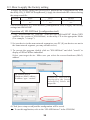
3. To execute the program, double click on "SILANIOinit" and click "search" to
display all XPort/WiPort embedded
Select your target device. Make sure you select the correct hardware (MAC)
address.
The contents will be
"Hardware (MAC) address IP address - type - version".
"xxxxx.rec" files will be
displayed in the [setup
record file]. Select the
proper file.
4. Click [save setup record] and the configuration will be saved.
To use this application, refer to the “SILANIOinit.txt” in the CD-ROM.
34
Operation of DeviceInstaller
1. Install DeviceInstaller to your PC and download the configuration file from the
utility CD to the appropriate folder (For example, "c:/setup/").
[ 5-4. DeviceInstaller Usage]
2. Set your device in the same network segment as your PC.(If your devices are not in
the same network segment, you may not able to set.)
3. Start Deveiceinstaller and click [Search] to display all XPort/WiPort embedded
Select your target device. Make sure you select the correct hardware (MAC)
address.
4. Click upgrade icon or go to [Device]
[Upgrade].
5.[Device upgrade wizard –step 1/5] will appear. Select [Custom install] and click
[Next].
6.[Device upgrade wizard –step 2/5] will appear. Click [Next].
7.[Device upgrade wizard –step 3/5] will appear. Select [Install setup records from a
file] and click [Browse].
8.Open the configuration file in the appropriate folder (For example, "c:/setup/") .
Click [Next].
9.[Device upgrade wizard –step 4/5] will appear. Click [Next]. Start the writing of
configuration files to the target device.
10.[Device upgrade wizard –step 5/5] will appear. “installation has finished” will be
displayed. Close the window.
For more details refer to DeviceInstaller User's Guide (\lantronix\Docs\
DeviceInstaller_UG.pdf ) ]
* Network address such as IP Address etc..would not be changed if you use
DeviceInstaller to set Setup Record.
Note
Please note that if you write inappropriate configuration file (e.g.
configuration file for different models or different versions of the
firmware), the XPort may not run correctly and will need repair.
35
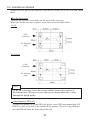
9-4. General-purpose I/O pins
XPort CP1 pin of SI-60F/60 is for the input pin between DR and ER lines of RS-232C. And,
XPort CP1 pin of SI-65 is for the output pin of RS-422/485 driver control. To read the input
status, send TCP/IP or UDP/IP command to the port number 30704.
CPI(DR and ER of RS-232C Control line) check command of SI-60F/60
Command
: 13h 00h 00h 00h 00h 00h 00h 00h 00h (9 nyte)
Response : 13h xxh 00h 00h 00h (5 byte)
* “xxh” bit 1 = 0:DR and ER of RS-232C Control line are non active.
* “xxh” bit 1 = 1:DR and ER of RS-232C Control line are active.( + 3V and above)
CPI(RS-422/465 driver) control command of SI-65
“xxh” in the sixth byte of command specifies the output status. ”xxh” in the second byte of
response shows the result.
Command : 1Bh 02h 00h 00h 00h xxh 00h 00h 00h 00h (9byte)
Response : 1Bh xxh 00h 00h 00h (5byte)
* “xxh” bit 1 = 0: Specify RS-422/485 driver is acrive as factory setting.
* “xxh” bit 1 = 1: Specify RS-422/485 driver is non acrive.
9-5. LANConnector Specification
LAN Connector Pin Assignment
Pin No.
1
2
3
4
5
6
7
8
Name
TX+
TXRX+
RX-
I/O Direction *1
Out
Out
In
In
-
Description
Transmission Data +
Transmission Data Reception Data +
Not Used
Not Used
Reception Data Not Used
Not Used
*1 "Out" means a direction to output signals from the converter. "In" means a
direction to input signals to the converter.
LAN Connector LED Display
Left LED
OFF
Solid Amber
Solid Green
Right LED
OFF
Blinking
Amber
Blinking
Green
Meaning
Does not connect Ethernet.
Connected 10 Base.
Connected 100 Base.
Idle
Communicating in the half-duplex mode.
(Lights only when communicating.)
Communicating in the full-duplex mode.
(Lights only when communicating.)
36
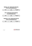
9-6. Installation Method
Rubber feet are put on the bottom of the device. Please set it on a flat and stable
place.
Fix the converter
There are the four M3 screw holes on the back of the converter.
When you fix the converter in place, screw the screws into those holes.
SI-60F
LAN
Connecter
AC Adaputer
plug
SI-60/SI-65
LAN
Connecter
AC Adaputer
plug
Note
To fix the converter, screw the screws within 7mm in the surface of
the bottom case. When you screw the screws deeper than that, it may
damage the board inside.
Attachment to DIN rail
To attach the product to 35mm DIN rail, please screw DIN attachment plate (SIDIN70) to M3 screw hall of the bottom of the product. Then, fix it by pushing it
into the DIN rail from the front side of the rail.
37
Chapter 10 Warranty and After-Sales Service
10-1. Troubleshooting
The "PWR" LED does not light.
< When using the AC adapter >
Is the AC adapter connected correctly?
Check that you plug the AC adapter
into the AC adapter plug or wall outlet
correctly.
< When powering from the connector or Check that you connect the RS-232C
connector or terminal block correctly.
terminal block >
Is the RS-232C connector or terminal
block connected correctly?
Neither the left and right LEDs for the LAN connector do not light or blink.
Is the LAN cable connected correctly?
Check that the connector is connected
correctly, or that the cable breaks, etc.
Try to connect with other port of hub.
Is the link LED on the switching hub
lighting?
Do you select the proper connection with Use the proper LAN cable which meets
the straight or cross-over cable for LAN? specification of the LAN connector for
the target devices.
Cannot find in the Deviceinstaller
Is SI-60/65/60F connected to the same
network segment with PC?
Is IP address of SI-60/65/60F duplicated
with other equipment ?
Can not serach, if SI-60/65/60F connected
to the differnt network segment.
If the IP address of SI-60/65/60F
duplicated with other equipment, take off
the LAN cable immediately and change
the IP address.
Refer to XPort user’s manual(XPort_
UG.pdf ) in the CD-ROM.
Does the security software on the PC
interrupt communications?
Check the settings in your OS or security
software.
Accessing from the Web browser cannot start the Web manager.
Do you correctly Assign IP Address,
subnet mask and gateway?
Do rooters, firewall or others on the
network interrupt communications?
Check the setup on the converter.
Contact your network administrator to
check.
Set from the Web browser but cannot reflect when opening it again.
Check the setting of IE.
Refer the Note of[6-1. Web Manager
Usage]
38
Cannot connect the converter from the network.
Is the IP address and port number set
correctly?
Search the device by using the deviceinstaller and check
the network address again.
Is SI-60/65/60F connected to the other Assign IP Address of rooter to default gateway of
network segment beyond the rooter? SI60/65/60F. Also condition of rooter firewall may need
to be change,contact your network administrator to
check.
Are you using COMPortRedirector?
Is the connection mode set to Server
Mode?
Please confirm if the COMPort No. which is set on the
COMPortRedirector is used on the side of the application
software.
Check the condition of SI60/65/60F.
Cannot communicate on the serial port side (SI-60F,SI-60)
Are Data Status LEDs blinking?
Is the RS-232C cable connected
correctly?
Is the DTE/DCE change-over switch
on the SI-60 set correctly?
Is the communication condition set
correctly?
Can it communicate with a serial port
of the PC?
It is working correctly if the SD and RD LEDs are blinking
on the timing of data transmission.
Note: This can be difficult to distinguish when the
transmitted data is too small.
Check that the connector is connected correctly, or that the
cable breaks, etc.
Check the specifications for the RS-232C connectors and
cables on the target devices, and conduct the proper setup.
Set to the same values the communication speed, data bits,
parity, stop bits, flow control, etc on both the converter and
target device.
Please confirm if it can communicate with the PC in
the communication condition of set-up mode by serial
connection.
For more details , refer to XPort user’s manual(XPort_
UG.pdf ) in the CD-ROM.
Cannot communicate on the RS-422/RS-485 port side(SI-65)
Are SR/RD LEDs blinking?
It is working correctly if the LEDs are blinking when the
data was transmitted on the RS-422/485 line.
Note: This can be difficult to distinguish when the
transmitted data is too small.
Is the terminal block connected
correctly?
Check that the terminal block is connected correctly,
that the cables are disconnected, that the cables
connected to the wrong connectors, and so on.
Is the DIP switch set correctly?
Set the DIP switch correctly following the connection
method, communication conditions, etc.
Connect the GND terminal on the converter to the
Are the GND terminal on the
converter and the signal grand on the signal grand on the target device.
target device, connected?
Is the communication condition set Set to the same values the communication speed, data
correctly?
bits, parity, stop bits, flow control, etc on both the
converter and target device.
39
10-2. Warranty and Repair
Warranty
Within a period of 12 months from the date of shipment, LINEEYE warrants that
your purchased products (excepting consumable parts such as the batteries and
software) are free of charge from any defects in material and workmanship, only
when the products are operated in accordance with procedures described in the
documents supplied by LINEEYE.
If the defects exist during the Warranty period, please send back the products to
LINEEYE distributors or LINEEYE office. LINEEYE will repair or exchange them
at no charge. In this case, the shipping charge will be at your own expense.
●The foregoing warranties are the sole warranties given by LINEEYE. Above
warranties shall not be applied to the products that have been modified, repaired
or altered (excepting by LINEEYE employees) or that have been subjected to
unusual physical or electrical stress, misuses, abuse, negligence or accidents.
LINEEYE disclaims all other warranties including the warranties of
merchantability, fitness for some particular purposes and noninfringement of
third party right. LINEEYE cannot promise that the software is error-free or will
operate without any interruption.
When you have some errors while operating the software, please refer to the
contents and modified programs shown on our web page (http://www.lineeye.
com). Please download it from there.
Repair
LINEEYE will repair the products at your own expense.
For malfunction, please contact the LINEEYE distributors where you purchased at.
Or, contact us directly.
If your product needs to be repaired, please read details about a repair on our web
page and ask for a repair.
10-3. After-Sales Service
Our web site contains information about his product. In addition, LINEEYE provides a
support for technical questions by Mail Form (click "contact us" on our web site).
For supports, the user registration is required. Please be sure to register from the registration
page on our web site.
40
●Head Office: 4F.,Marufuku Bldg.,39-1, Karahasi, Nishihiragaki-cho,
Minami-ku, Kyoto, 601-8468, Japan
TEL: 075-693-0161 FAX: 075-693-0163
●Technical Center: 8-49 Kouen-cho, Nagahama, Shiga, 526-0065
TEL: 0749-63-7762 FAX: 0749-63-4489
URL: http://www.lineeye.com
Printed In Japan
M-G3606560FE/SI