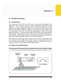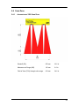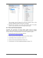
1
chroma+scan 3x00 Version 4.11.11.31 Copyright © 2010-2013 by LMI Technologies, Inc. All rights reserved. Proprietary This document, submitted in confidence, contains proprietary information which shall not be reproduced or transferred to other documents or disclosed to others or used for manufacturing or any other purpose without prior written permission of LMI Technologies Inc. No part of this publication may be copied, photocopied, reproduced, transmitted, transcribed, or reduced to any electronic medium or machine readable form without prior written consent of LMI Technologies, Inc. Trademarks and Restrictions DynaVision, chroma+scan®, Selcom®, FireSync®, and Sensors That See® are registered trademarks of LMI Technologies, Inc. Any other company or product names mentioned herein may be trademarks of their respective owners. Information in this manual is subject to change. This product is designated for use solely as a component and as such it does not comply with the standards relating to laser products specified in U.S. FDA CFR Title 21 Part 1040. LMI Technologies, Inc. 1673 Cliveden Ave. Delta, BC V3M 6V5 Telephone: +1 604 636 1011 Facsimile: +1 604 516 8368 www.lmi3D.com Table of Contents Table of Contents ............................................................................................................ 3 1 Laser Safety ............................................................................................................. 6 1.1 General Information .......................................................................................... 6 1.2 Laser Classification ........................................................................................... 7 1.2.1 Laser Classes ............................................................................................ 7 1.2.2 User Precautions and OEM Responsibilities .............................................. 8 1.2.3 Class 3B/lllb OEM Responsibilities ............................................................. 8 1.3 Requirements for Laser Systems Sold or Used In the USA ............................. 10 1.4 chroma+scan 3x00 Laser Safety Specification ................................................ 10 2 Proper Handling and Precautions ........................................................................... 11 2.1 System Installation .......................................................................................... 11 2.1.1 Component Grounding ............................................................................. 11 2.1.2 Shielded Cable ......................................................................................... 11 2.1.3 Power Supply ........................................................................................... 11 2.1.4 Uninterruptible Power Supply (UPS) ........................................................ 12 2.1.5 Installation Environment ........................................................................... 12 2.2 Temperature and Humidity .............................................................................. 12 2.3 Maintenance ................................................................................................... 12 2.4 Laser Lifetime ................................................................................................. 12 3 Getting Started ....................................................................................................... 13 3.1 Components.................................................................................................... 13 3.1.1 Sensors.................................................................................................... 14 3.1.2 Master ...................................................................................................... 15 3.1.3 Cables...................................................................................................... 15 3.1.4 Power Supply ........................................................................................... 15 3.1.5 Station Computer ..................................................................................... 16 3.1.6 Client Computer ....................................................................................... 17 3.1.7 Gigabit Ethernet Switch ............................................................................ 17 3.2 Connections .................................................................................................... 17 3.2.1 Sensors to Master .................................................................................... 17 3.2.2 Station to Client Computer ....................................................................... 17 3.2.3 Power Supply to Master/Station ............................................................... 18 3.2.4 Safety Interlock ........................................................................................ 18 3.2.5 Connection Guidelines ............................................................................. 18 3.3 FireSync Client (Basic) .................................................................................... 19 3.3.1 Installation ................................................................................................ 19 3.3.2 Connection ............................................................................................... 20 3.3.3 Server Health ........................................................................................... 21 3.3.4 Sensor Enumeration ................................................................................ 22 3.3.5 Sensor Health .......................................................................................... 23 3.3.6 Sensor Data ............................................................................................. 24 4 Product Overview ................................................................................................... 25 4.1 Introduction ..................................................................................................... 25 4.2 Measurement Principles .................................................................................. 25 4.3 True Differential Measurement ........................................................................ 26 4.4 Vision .............................................................................................................. 26 4.5 Tracheid .......................................................................................................... 26 4.6 High Scan Rates ............................................................................................. 26 4.7 Temperature Compensated Ranges ............................................................... 26 5 chroma+scan 3x00 Sensor Specifications .............................................................. 27 5.1 Models ............................................................................................................ 27 5.2 Performance ................................................................................................... 28 5.3 Specifications .................................................................................................. 28 5.4 Scan Zone....................................................................................................... 29 5.4.1 chroma+scan 3350 Scan Zone ................................................................ 29 5.4.2 chroma+scan 3155/3250 Scan Zone........................................................ 30 5.5 Dimensions and Mounting ............................................................................... 31 5.5.1 chroma+scan 3155 Sensor Dimensions ................................................... 31 5.5.2 chroma+scan 3250 Sensor Dimensions ................................................... 32 5.5.3 chroma+scan 3350 Sensor Dimensions ................................................... 33 5.6 Cleaning .......................................................................................................... 34 6 System ................................................................................................................... 35 6.1 Overview ......................................................................................................... 35 6.2 FireSync Master and Station ........................................................................... 36 6.3 Power Supply .................................................................................................. 36 6.4 Encoder .......................................................................................................... 37 6.5 Wiring and Connections .................................................................................. 37 6.5.1 Safety Interlock ........................................................................................ 37 6.6 Frame Design ................................................................................................. 37 6.6.1 chroma+scan 3350 System Configuration ................................................ 38 6.6.2 chroma+scan 3155/3250 System Configuration ....................................... 39 6.7 System Calibration Target ............................................................................... 40 7 Software ................................................................................................................. 41 7.1 FireSync Station .............................................................................................. 41 7.1.1 Installation ................................................................................................ 41 7.1.2 PC with Existing Station Software ............................................................ 43 7.1.3 Network Interface Configuration ............................................................... 43 7.1.4 Disabling UAC on Windows 7 .................................................................. 44 7.1.5 System Upgrade ...................................................................................... 45 7.2 FireSync Client (Complete) ............................................................................. 45 7.2.1 Installation ................................................................................................ 45 7.2.2 Connection ............................................................................................... 46 7.2.3 Server Upgrade........................................................................................ 46 7.2.4 System Setup........................................................................................... 47 7.2.4.1 System Setup Tab ............................................................................ 49 7.2.4.2 System Web Tab .............................................................................. 52 7.2.4.3 System Detection Tab ....................................................................... 54 7.2.4.4 System Calibration Tab ..................................................................... 56 7.2.5 Server Setup ............................................................................................ 59 7.2.5.1 Server Setup Tab .............................................................................. 59 7.2.5.2 Server Health Indicators .................................................................... 60 7.2.6 Group Setup............................................................................................. 61 7.2.6.1 Group Sections Tab .......................................................................... 61 7.2.7 Sensor Setup ........................................................................................... 63 7.2.7.1 Sensor Setup Tab ............................................................................. 63 7.2.7.2 Sensor Obstructions Tab .................................................................. 64 7.2.7.3 Sensor Health Indicators ................................................................... 65 7.2.8 Event Channel ......................................................................................... 66 7.3 File Formats .................................................................................................... 67 7.3.1 Server Settings ........................................................................................ 67 7.3.2 Calibration Target .................................................................................... 74 7.3.3 Calibration Output .................................................................................... 75 7.4 Modes and Messages ..................................................................................... 76 7.4.1 Free Mode ............................................................................................... 77 7.4.2 Calibration Mode ...................................................................................... 78 7.4.3 Web Mode ............................................................................................... 79 7.4.4 Detection Mode ........................................................................................ 81 7.5 Health Indicators ............................................................................................. 83 7.6 Sample Code .................................................................................................. 83 7.7 Multiple Server Usage ..................................................................................... 83 7.8 Server Simulation ............................................................................................ 84 8 System Updates ..................................................................................................... 88 8.1 FireSync Station Updates................................................................................ 88 8.2 Client and Firmware Updates .......................................................................... 89 9 Replacing System Components ............................................................................. 90 10 Warranty ................................................................................................................ 92 10.1 Warranty policies............................................................................................. 92 10.2 Return policy ................................................................................................... 92 11 Getting Help ........................................................................................................... 93 Section 1 1 Laser Safety 1.1 General Information The laser light sources used in LMI Sensors are semiconductor lasers emitting visible light. LMI Laser Sensors have a 2/ll, 3R/llla or 3B/lllb classification depending on model. Class 2/ll and 3R/llla sensors are referred to as “products” indicating that they fully comply with the standards relating to laser products specified in IEC 60825-1 and U.S. FDA CFR Title 21 Part 1040 except for deviations pursuant to Laser Notice No. 50, dated July 26, 2001. Class 3B/lllb sensors are sold only to qualified OEM’s as “components” for incorporation into their own equipment. The sensors do not incorporate safety items which the OEM is required to provide in their own equipment (e.g. remote interlocks, key control). As such these sensors do not fully comply with the standards relating to laser products specified in IEC 60825-1 and FDA CFR Title 21 Part 1040. Caution! Use of controls or adjustments or performance of procedures other than those specified herein may result in hazardous radiation exposure. 6 1. International Standard IEC 60825-1 (2001-08) Consolidated edition, Safety of laser products – Part 1: Equipment classification, requirements and user’s guide 2. Technical Report TR 60825-10, safety of laser products – Part 10. Application guidelines and explanatory notes to IEC 60825-1 3. Laser Notice No. 50, FDA and CDRH http://www.fda.gov/cdrh/rad-health.html 1.2 Laser Classification 1.2.1 Laser Classes Class 2/ll laser products: Class 2/ll laser products would not cause permanent damage to the eye under reasonably foreseeable conditions of operation, provided that any exposure can be terminated by the blink reflex (assumed to take 0.25 sec). Because classification assumes the blink reflex, the wavelength of light must be in the visible range (400 nm to 700 nm). The Maximum Permissible Exposure (MPE) for visible radiation for 0.25 second is 25 Watt per square meter, which is equivalent to 1 mW entering an aperture of 7 mm diameter (the assumed size of the pupil). Labels reprinted here are examples relevant to the laser classes. For detailed specifications observe the label on your laser sensor Class 3R/llla laser products: Class 3R/llla laser products emit radiation where direct intrabeam viewing is potentially hazardous, but the risk is lower than for 3B/lllb lasers. Fewer manufacturing requirements and control measures for users apply than for 3B/lllb lasers. Class 3B/lllb laser components: Class 3B/lllb components are unsafe for eye exposure. Usually only ocular protection would be required. Diffuse reflections are safe if viewed for less than 10 seconds. 7 1.2.2 User Precautions and OEM Responsibilities The specific user precautions as specified in IEC 60825-1 and FDA CFR Title 21 Part 1040 are: Requirements Class 2/ll Class 3R/3a Class 3B/3b Remote interlock Not required Not required Required** Required** Key control Not required Not required Cannot remove key when in use Power-On delays Not required Not required Required** Beam attenuator Not required Not required Required** Emission indicator Not required Not required Required** Warning signs Not required Not required Required** Beam path Not required Terminate beam at useful length Terminate beam at useful length Specular reflection Not required Prevent unintentional reflections Prevent unintentional reflections Eye protection Not required Not required Required under special conditions Laser safety officer Not required Not required Required Not required Required for operator and maintenance personnel Required for operator and maintenance personnel Training LMI Class 3B/lllb laser components do not incorporate the safety items indicated by asterisks ** in the table above. These items must be added and completed by the OEM in the system design. 1.2.3 Class 3B/lllb OEM Responsibilities LMI Technologies has filed reports with the FDA to assist the OEM in achieving certification of their laser products. The OEM can reference these reports by an accession number that will be provided upon request. 8 Detailed descriptions of the safety items that must be added to the OEM design are listed below: Remote Interlock A remote interlock connection must be present in Class IIIB laser systems. This permits remote switches to be attached in serial with the keylock switch on the controls. The deactivation of any remote switches must prevent power from being supplied to any lasers. Key Control A key operated master control to the lasers that prevents any power from being supplied to the lasers while in the OFF position. The key can be removable in the OFF position but the switch must not allow the key to be removed from the lock while in the ON position. Power-On Delays A delay circuit is required that illuminates warning indicators for a short period of time prior to supplying power to the lasers. Beam Attenuators A permanently attached method of preventing human access to the laser radiation other than switches, power connectors or key control must be employed. On some LMI laser sensors, the beam attenuator is supplied with the sensor as an integrated mechanical shutter. Emission Indicator It is required that the controls that operate the sensors incorporate a visible or audible indicator when power is applied and the lasers are operating. If distance (>2 m between sensor and controls) or mounting of sensors intervenes with observation of these indicators, a second power-on indicator should be mounted at some readily observable position. When mounting the warning indicators, it is important not to mount them in a location that would require human exposure to the laser emissions. Warning Signs Laser warning signs must be located in the vicinity of the sensor such that they will be readily observed. Examples of laser warning signs are: 9 FDA Example IEC Example 1.3 Requirements for Laser Systems Sold or Used In the USA The OEM’s laser system which incorporates laser components or laser products manufactured by LMI Technologies requires certification by the FDA. It is the responsibility of the OEM to achieve and maintain this certification. OEM’s are advised to obtain the information booklet Regulations for the Administration and Enforcement of the Radiation Control for Health and Safety Act of 1968: HHS Publication FDA 88-8035. This publication, containing the full details of laser safety requirements, can be obtained directly from the FDA, or downloaded from their website at http://www.fda.gov/cdrh. 1.4 chroma+scan 3x00 Laser Safety Specification Laser Classification: 3B/IIIb laser component Peak Power: 130mW Emitted Wavelength: 660nm 10 Section 2 2 Proper Handling and Precautions 2.1 System Installation 2.1.1 Component Grounding All sensors should be grounded to the earth/chassis through their housing. For sensors with through-hole mounts, this can be accomplished by using star washers on the mounting bolts. The star washers must cut through the powder coating to provide electrical conductivity from the mounting hardware to the sensor housing. For sensors with tapped hole mounts, conductive hardware must to be used between the sensor and the frame. This must be checked with a multi-meter by ensuring electrical continuity between the frame and the connector housing on the sensor. It is imperative that the scan frame or chassis that the sensor is mounted to is connected to earth ground. Master networking products should have the housing connected to earth ground. This can be accomplished using star washers on the mounting holes or through the earth ground connection located on the rear of the Master 1200 and 2400. FireSync Networking products should be installed inside electrical cabinets that are suitably grounded to earth ground. 2.1.2 Shielded Cable LMI Technologies recommends the use of shielded cables in all environments to ensure isolation from electrical noise. The shield should be electrically connected to both the sensor housing through the connector housing and to the electrical box containing either the Master (network systems) or the power supply (standalone sensors). LMI Technologies supplies both shielded FireSync cordsets and shielded FireSync cable for building cordset. 2.1.3 Power Supply The user must provide a suitable +48VDC power supply for the system capable of handling an infinite capacitive load. These power supplies must be isolated such that DC ground is NOT tied to AC ground. The power supply should be of a suitable capacity for the size of the system. LMI Technologies recommends the Phoenix Contact QUINT series of power supplies. 11 2.1.4 Uninterruptible Power Supply (UPS) To maximize the life of the sensor, LMI Technologies recommends the use of an on-line double-conversion UPS whenever the quality of the electrical supply to the system is poor. This includes but is not limited to when the electrical supply: contains high frequency noise (due to other electronics, electric motors or other factors) is prone to “brown-out” conditions or large voltage fluctuations is prone to electrical surges or spikes due other components or electrical storms. LMI Technologies recommends the Tripp Lite SU2200RTXL2UA UPS. 2.1.5 Installation Environment To prevent damage to LMI 3D sensors and ensure reliable operation, avoid installing the sensor in locations: that are humid, dusty, or poorly ventilated with a high temperature such as a place exposed to direct sunlight where there are flammable or corrosive gases where the unit may be directly subjected to vibration or impact water, oil, or chemicals may splash onto the unit where static electricity is easily generated 2.2 Temperature and Humidity LMI 3D Sensors are rated for operation between 0- 50°C, and 25-85% Relative Humidity (non-condensing). 2.3 Maintenance LMI 3D sensors are high-precision optical instruments. To ensure the highest accuracy is achieved in all measurements, the windows on the front of the sensor should be kept clean and clear of debris. Use dry, clean air to remove dust or other dirt particles. If dirt remains, clean the windows carefully with a soft, lint-free cloth using an ammonia based cleaner. Ensure that no residue is left on the windows after cleaning. 2.4 Laser Lifetime LMI Technologies uses semiconductor lasers in their 3D measurement sensors. To maximize the lifespan of the sensor it is recommended to turn off the laser by stopping the sensor whenever it is not in use. Another method for maximizing laser lifetime is to enable the laser watchdog feature which automatically turns off lasers in a sensor when there is no conveyor chain movement (see Section 7.2.4.1 for details). 12 Section 3 3 Getting Started Warning! chroma+scan 3x00 sensors are class 3B/IIIb components. Please read Section 1: Laser Safety above, and institute the necessary safety precautions before turning these sensors on. This section provides a brief introduction to the chroma+scan 3x00. It identifies the components supplied by LMI Technologies, and the additional components required to get a basic system up and running. This is followed by instructions on how to connect these components together, and how to install and run our client software to acquire basic profile data to ensure sensor operation out-of-the-box. More detailed information is given in the sections that follow this "Getting Started" guide. 3.1 Components LMI Technologies provides chroma+scan 3155, 3250, or 3350 sensors, a Master and information on cables to connect the Sensors, Master, and user provided equipment. The user must provide a power supply, station computer, client computer, a Gigabit Ethernet switch, and cables to connect the sensors and the Master. 13 3.1.1 Sensors chroma+scan 3155 chroma+scan 3250 chroma+scan 3350 14 3.1.2 Master FireSync Master 1200 or 2400 Generation 2 3.1.3 Cables Network Cordset The above cable is available from LMI and/or its suppliers. Also required are standard CAT5e Gigabit Ethernet cables (RJ45 connectors) to connect the user Station PC to the client computer and the Sensor network GigE switch. 3.1.4 Power Supply The user must provide a suitable +48 VDC power supply for the system. The output from all power supplies must be isolated from AC ground. LMI Technologies recommends the use of Phoenix Contact, QUINT series 48V DC power supplies for the Master and sensor power. The current rating of the power supply should be equal to the number of sensors connected to Master. For example, it is recommended that a 16 sensor system uses a +48V power supply capable of delivering 16A. 15 The Phoenix QUINT series power supplies are DIN rail mounted devices that can be connected in parallel to increase the overall available power. +48 VDC Model: Order number: 3.1.5 QUINT-PS-100-240AC/48DC/10 2938248 Station Computer The Station is a user-supplied PC used to process data from the sensors and to interface with the client PC. The software that runs on the station performs three key roles: Data processing through the kServer application. Management of the kServer process through the kManagementServer application. Diagnostic logging of the system through the kDashboard application. Multiple stations can be used in a system. However, for multiple station systems, the firmware and software upgrade package must be run individually per station. Requirements Minimum 2x gigabit (1 Gbps) Ethernet ports (Recommended: Intel PRO/1000 Network Adaptor or equivalent, x2) Pentium 4, Pentium D, or Pentium Core Duo at 2.0 GHz or above Minimum 2 GB of RAM Minimum 10 GB of Hard Disk Space Windows XP SP3 or Embedded XP, Windows 7 Professional 32-bit or 64-bit* Any firewall software must be disabled The network card driver should be updated to the latest available version USB 2.0 ports (recommended) *While Windows XP is technically supported, Embedded XP is strongly recommended. Windows XP lacks the capabily to support a hard power-down situation and it will be the responsibility of the user to initiate a proper shutdown process every time power disconnected. IN Port The IN port is a Gigabit Ethernet link to a Master. It communicates on the sensor (Private) network. The IN port IP address should always be on the 90.X.X.X subnet. This address can be changed by sending a “Set Private IP” command to the Station, which is done, typically, to support multiple station configurations. The valid addresses are 90.0.0.1 to 90.0.0.5. The default IP is 90.0.0.1. A typical configuration is: IP address : 90.0.0.1 Subnet Mask 255.0.0.0 16 Out Port The OUT port is a gigabit Ethernet link to the client (Public) network. It is the gateway through which the user communicates with the sensor network. The OUT port can be set to any IP address except addresses belonging to the 90.X.X.X subnet. A typical configuration is: IP address : 192.168.1.10 Subnet Mask 255.255.255. Section 7.1 describes the steps of setting up a PC to be a FireSync Station node. 3.1.6 Client Computer The user must provide a suitable client computer. This must be equipped with a Gigabit Ethernet port to communicate with the FireSync Station. The client Interface to the Station is OS independent. However, Windows XP or Windows 7 (32/64-bit) is required on this computer in order to install and run LMI’s FireSync Client demonstration application. 3.1.7 Gigabit Ethernet Switch The user must provide a suitable Gigabit Ethernet Switch for the Sensor network. The Gigabit Ethernet switch is connected to each Sensor through the Ethernet RJ45 connection through the Sensor’s network cordset. The Gigabit Ethernet Switch is connected to the Master’s Link port with a standard CAT5e Gigabit Ethernet cable (RJ45 connectors). 3.2 Connections 3.2.1 Sensors to Master Please refer to the FireSync Network User Manual for complete details on connecting the sensors to the FireSync Master and Station. 3.2.2 Station to Client Computer A standard CAT5e Gigabit Ethernet cable (RJ45 connectors) is used to connect the Station PC, via the RJ45 connector "OUT", to a Gigabit Ethernet port on the client computer. If two or more Station PCs are required in the system, this connection can be made to a single client computer via separate Gigabit Ethernet cards, via a Gigabit Ethernet switch, or via multiple processing stations. The station output port is used to send data to the client (port mapping is established during the FireSync Station Software installation process, described in Section 7.1). The client PC’s IP address will have to be configured to the same subnet as the station’s OUT port: In the Windows control panel, select “Network Connections” 17 Double-click on the name of the connection being used Click “Properties”, and double-click on “Internet Protocol (TCP/IP)”. This window will show up: Select “Use the following IP address”, and input the Subnet mask shown above. The IP entered must be on the same subnet as the station’s (the IP address shown above is appropriate for connecting to a station with the default IP address of 192.168.1.10). Click OK. Click OK on the Connection properties window. The client PC has now been configured to connect to a FireSync Station. After this procedure is complete, the station can be connected to via FireSync Client (See Section 3.3.2). 3.2.3 Power Supply to Master/Station The +48 VDC power supply is wired to the Phoenix connectors on the Master. Refer to the FireSync Network User Manual for details. 3.2.4 Safety Interlock The Safety Interlock signal allows the user to turn on and off all light sources in sensors without disrupting power to the system. If the sensor is “safety-enabled”, laser safety control signal must be provided at the Master and at all Slaves for sensors to properly function. Please refer to the FireSync Network User Manual for Safety Interlock connection requirements. 3.2.5 the the the the Connection Guidelines The maximum sensor load per station varies with station performance. Station CPU usage should be monitored to ensure any core does not exceed 80% usage. Sensors can be grouped into different sensor networks for multi-station systems. Each station can only have a single network connection to the sensor network. However, each station can have multiple network connections to the client network 18 which allows different client PCs to process data separately. This is accomplished through the use of two NICs in the station, each on a different subnet with a different static IP. Different channels can then be set up to direct data to separate client PCs. 3.3 FireSync Client (Basic) FireSync Client is a software application that can be used to set up, demonstrate, or diagnose problems with a chroma+scan 3x00 system. The following sections describe how to use FireSync Client to connect to a system and verify that all connected devices are functioning normally. For a detailed description of the FireSync Client application, see the section entitled FireSync Client (Complete) in the Software chapter of this manual. 3.3.1 Installation The FireSync Client application is available for Windows, and can be downloaded from the LMI Technologies support website. To begin, download the software and install it on a suitable client machine. The client machine should have an Ethernet adaptor that can be configured for a static IP address and that supports 1000 Mb/s operation. The user provided Station PC is typically configured with the address 192.168.1.10, but can be configured as required. Set the client machine to an available address on the same subnet (e.g. 192.168.1.9) and then connect a suitable Ethernet cable from the client machine to the Station. If you are using multiple FireSync Stations, you may need to connect to each Station individually in order to assign each Station unique IP addresses (both public and private), using the Set IP command from the Server menu. After each Station has been assigned a unique address, you can reconnect to all stations simultaneously. 19 3.3.2 Connection After starting FireSync Client, use the Connect (left-most) icon in the toolbar to display the Connect... dialog. To connect to a single server, enter the IP address of the server to which you wish to connect, and then click OK. To connect to multiple servers simultaneously, click the Advanced… button, add the IP addresses of the servers, and then click OK. 20 3.3.3 Server Health After connecting, click on the device tree node for each server and then click on the Health visualization tab, as show below. Health indicators can be used to help diagnose a wide variety of conditions. Note that some indicators are updated constantly, while others are only updated if the system is in the Running state. 21 3.3.4 Sensor Enumeration Each server can have a Top group of sensors, a Bottom group of sensors, or both. Use the pull-down lists in a Server Setup tab to specify the number of sensors in each group. When the number of sensors in either group is changed, the number of sensor nodes in the device tree changes accordingly. Assign a serial number to each sensor by right-clicking on the sensor’s node in the device tree, and selecting a serial number from the list of detected sensors. If you do not see a specific sensor (or any sensors) in the context-menu, it implies that the sensor was not detected. If this is the case, check the cabling, cycle the power, and then reconnect with kClient. 22 3.3.5 Sensor Health After creating entries for each sensor, click on the device tree node for each sensor and review the Sensor Health visualization tab. As with the server health indicators, some sensor health indicators are updated constantly, while others are only updated if the system is in the Running state. 23 3.3.6 Sensor Data To view live laser profile data from a sensor, click on the sensor’s node in the device tree, and then select the Obstructions tab. Press the Start button in the FireSync Client toolbar. The Profile visualization tab will display live laser profile measurements. This display can be used in conjunction with a stationary or moving target to verify that laser profiling is operating correctly. 24 Section 4 4 Product Overview 4.1 Introduction The chroma+scan 3155, 3250, and 3350 are the new-generation, high-speed, highdensity 3D profile scanning system for primarily green-side edger and trimmer applications. These systems offer high density, along-board profile data and high resolution across-board sampling at 2000 Hz. The chroma+scan 3350 systems offers additional optimization possibilities by providing colour images of board surfaces, while the chroma+scan 3250 system offers tracheid measurements at 500 Hz and profile sampling at 2500 Hz. The sensors are based on LMI's field-proven FireSync platform, which provides a synchronized, scalable, distributed vision processing architecture for building reliable, high performance systems. High reliability and simple, rapid installation are achieved with a single cable for power, data, and synchronization. The chroma+scan 3x00 sensor system consists of a number of chroma+scan 3x00 sensors, plus a FireSync Master and a FireSync Station or a user-provided Station PC. A user-provided client computer communicates with station computers to control the chroma+scan system and to receive data via Gigabit Ethernet. 4.2 Measurement Principles The chroma+scan 3x00 sensors function on the principle of structured light triangulation. A semiconductor laser with special optics projects a fan of light onto the target. A digital 25 camera mounted at an angle to the laser plane acquires images of the light pattern created on the target. These images contain the basic information needed to compute distances to the target. 4.3 True Differential Measurement The chroma+scan 3x00 sensors can be aligned co-planar top-to-bottom and side-to-side down the length of the system. This prevents profile measurement errors that could be introduced by hard-to-control mechanical realities such as chain vibration and boards bouncing as they are transported through the scanner system. 4.4 Vision chroma+scan 3350 sensors incorporate colour imagers and LED lighting into their design. This provides a simple and reliable method of capturing features on the top and bottom surfaces of the boards along the length of the system. 4.5 Tracheid chroma+scan 3250 sensors have the ability to measure the tracheid cells, reporting the angle of the grain, the scatter along that axis, and the effect of the tracheid on the size of the laser spots. 4.6 High Scan Rates The chroma+scan 3x00 sensor family provides profile scan rates of 2000 Hz (2500 Hz for the chroma+scan 3250). At the same time, the sensors maintain excellent dark wood performance (equivalent to level 19 on the Kodak gray scale chart), insensitivity to laser saturation, and immunity to ambient light. 4.7 Temperature Compensated Ranges Chroma+scan 3x00 sensors are calibrated at several temperature points in their operational range to ensure reliable and accurate range measurement throughout changes in ambient temperature. 26 Section 5 5 chroma+scan 3x00 Sensor Specifications This section presents sensor specific chroma+scan 3x00 information. It describes the different models, and gives dimensions of the scan zone and sensor. 5.1 Models chroma+scan 3x00 sensors are available in the following models: chroma+scan 3155: 2000 Hz profiler, safety interlocked chroma+scan 3250: 2500 Hz profiler, safety interlocked, with tracheid chroma+scan 3350: 2000 Hz profiler with high-res vision, safety interlocked These sensors all have identical mounting footprints to allow for future upgrades. The chroma+scan 3350 sensors are slightly taller to provide the internal LED lighting required for vision. The chroma+scan 3155 and 3250 offer an extended scan range. All these models and have safety interlock for lasers and LED control. Safety interlocked sensors require the use of the FireSync Sensor Cordset Version 2 to provide a +48 VDC control signal to each sensor in the system. This signal is controlled at the FireSync Master or Slave by the Safety Interlock input. Without this signal, all of the light sources in the sensor, including the lasers, will be disabled. Please refer to the FireSync Network User’s Manual for more information on safety interlock. For backwards compatibility, safety interlocked sensors can be used in older systems by modifying the sensor cordset to a safety-bypass cable, or by providing a short safetybypass patch cable at the sensor end. Either of these solutions will provide the required +48 VDC control signal to the sensor, overriding the safety interlock. This is an alternative to re-cabling older systems. 27 5.2 Performance Profile Accuracy ±0.38 mm ±0.015 in Profile X-Resolution 8.5 mm 0.333 in Profile Y-Resolution @ 1m/s (197 fpm) 0.5 mm 0.020 in ( @ 1.25m/s (246 fpm) for chroma+scan 3250) 5.3 Specifications Operating Temperature 0 - 50°C 32 - 122°F (Non-condensing) Input Power +48VDC @ 1A Housing IP67, Powder Coated, Aluminum 28 5.4 Scan Zone 5.4.1 chroma+scan 3350 Scan Zone Standoff (SO) 559 mm 22.0 in Measurement Range (MR) 152 mm 6.0 in Field of View (FOV) through entire range 610 mm 24.0 in 29 5.4.2 chroma+scan 3155/3250 Scan Zone Standoff (SO) 508 mm 20.0 in Measurement Range (MR) 203.2 mm 8.0 in Field of View (FOV) through entire range 609.6 mm 24.0 in 30 5.5 Dimensions and Mounting 5.5.1 chroma+scan 3155 Sensor Dimensions 31 5.5.2 chroma+scan 3250 Sensor Dimensions 32 5.5.3 chroma+scan 3350 Sensor Dimensions 33 The sensor can be mounted with either M8 or 5/16" hardware. Provision to adjust the position and orientation of the sensor to align its laser plane with the laser planes of other sensors, above and beside, is highly recommended. This alignment is critical to prevent sensor crosstalk and ensure true differential measurements; aligned laser planes also provide a better appearance to the end user of the system. Caution! Use star washers to mount the sensors to the frame to ensure proper component grounding. Please refer to section 2 for more information on component grounding. The laser dots are emitted through the 4 clear round windows in-line with the black painted channel along the window face of the sensor. This channel controls laser reflections in the system as well as giving a target to aim the lasers of opposing sensors at during sensor installation and alignment. The laser dots down the length of the system are required to be aligned within these painted channels to control laser reflections in the system. A more critical alignment can be made for aesthetic purposes. The profile cameras are located behind the two red tinted windows and the vision cameras (chroma+scan 3350 sensors only) are located in the two clear windows adjacent to the profile camera windows. The Tracheid camera windows (chroma+scan 3250 only) are located in-line with the laser windows and the painted black alignment channel. When mounting the sensor, ensure that there are no obstructions between the camera windows and the Scan Zone. 5.6 Cleaning The windows on a sensor must be kept clean and free of debris at all time. If the windows become dirty, clean them with an ammonia-based cleaner only. Window cleanliness for the chroma+scan cs3250 is extra critical as any distortion of laser spots or impediment to the cameras’ view can cause error in the Tracheid measurement. 34 Section 6 6 System 6.1 Overview A chroma+scan 3x00 system consists of some or all of the following components: chroma+scan 3155, 3250 or 3350 sensors FireSync Master 1200 or Master 2400 User-supplied Station PC(s) FireSync Cordsets Power Supply Encoder Client Computer Scanner Frame System Calibration Target Power and Encoder Wiring In a typical system, up to 24 chroma+scan 3x00 sensors are placed top-and-bottom and end-to-end along the length a scanner frame. However, in some systems the bottom sensors may be omitted if mechanical constraints of the chain design prevent mounting sensors there. The Master is the central hub of the system, and provides power, encoder, Safety Interlock, and digital I/O routing. Each sensor and the encoder connect to the Master via sensor cordsets. The power supply provides power to the Master and FireSync Station (if applicable). The Master distributes power to the sensors and encoder. A single CAT5E Gigabit Ethernet cable provides the communication link from the Station to the Client computer. The FireSync Master 1200 supports 12 sensors while the FireSync Master 2400 supports 24 sensors A server application, running on the Station, integrates data from the encoder and sensors, and transmits the processed output to the client. 35 6.2 FireSync Master and Station Complete details of the FireSync Master 1200, Master 2400, and Station are provided in the FireSync Network User Manual. The FireSync Master 1200 provides: 12 FireSync interfaces An encoder interface A safety interlock interface A digital I/O interface System synchronization The FireSync Master 2400 provides: 24 FireSync interfaces An encoder interface A safety interlock interface A digital I/O interface System synchronization The user-supplied Station PC provides: A Gigabit Ethernet interface to the sensor network One or more Gigabit Ethernet interfaces to the client network NOTE: The vision output from chroma+scan 3350 sensors can exceed the networking and data processing capacity of a single station computer. There should typically be one dedicated station for every 5 - 10 chroma+scan 3350 sensors. The actual maximum number of sensors per station varies with the quality of network adaptors, drivers, and switches, as well as the data processing capacity of the station. As a starting point, LMI recommends a quad-core CPU with 2GB of RAM and 2-3 Gigabit Ethernet network adaptors. Testing should be performed prior to deployment to confirm that station computers can meet the networking and processing requirements of the application. 6.3 Power Supply The user must provide a suitable +48 VDC power supply for the system. These power supplies must be isolated! This means that DC ground is NOT tied to AC ground! LMI Technologies recommends the use of a Phoenix Contact, QUINT, 10 Amp power supply (for +48 VDC). The Phoenix QUINT series power supplies are DIN rail mounted devices that can be connected in parallel to increase the overall available power. +48 VDC Model: Order number: QUINT-PS-100-240AC/48DC/10 2938248 36 6.4 Encoder The user must provide a suitable encoder. The requirements are: Differential quadrature output (maximum 18 V) +5 VDC power supply input The encoder interface on the Master provides the following: X4 quadrature decoding Maximum 300 kHz count rate +5 VDC to power the encoder The user should choose an encoder with the appropriate number of pulses per revolution to match the transport mechanism and speed. 6.5 Wiring and Connections Refer to the FireSync Network User Manual for details on connecting the power supplies, encoder, Master, Slave, Station, and sensors in a chroma+scan 3x00 sensor system. 6.5.1 Safety Interlock Safety Interlock is a signal controlled by the Safety input on both the Master and the Slave. Safety- must be connected to the 48VGND and Safety+ must be energized by +48 VDC before any lights in the system will receive power. If this input is disabled, although the sensors are powered and running, the light sources are disabled. Systems with Safety Interlock require: Safety interlock-enabled sensors FireSync Sensor Cordsets Version 2 An external switch connecting the Safety Interlock signal at the Master to +48 VDC Refer to the FireSync Network User Manual for details on wiring the Safety Interlock circuit. 6.6 Frame Design The scan frame supports the sensors above and below the chain deck to the maximum size of the boards to be scanned. Typically, there are 10 to 12 sensors mounted above the chain and another 10 to 12 sensors mounted below. This provides complete coverage of the top and bottom surfaces of the boards. A means of adjusting the sensors’ location and orientation is required to ensure that the sensors do not experience crosstalk and also to ensure that the board thickness is measured differentially. 37 The scan frame must also be connected to earth ground to provide a ground path for the sensors. 6.6.1 chroma+scan 3350 System Configuration The above separation of sensors provides a full 6 inch overlapped scan zone range that begins from 1 inch below the chainway and extends to 5 inches above the chainway. No sensor stagger is required in the system (top to bottom or side to side). 38 6.6.2 chroma+scan 3155/3250 System Configuration The above configuration of chroma+scan 3155/3250 sensors provides a full 6 inch overlapped scan zone starting from 1 inch below the chainways and extends to 5 inches above the chainways. The extended range of the chroma+scan 3155/3250 sensors provides an additional 2 inches of coverage from the top sensors above this overlapped zone as well as an additional 2 inches below the overlapped zone from the bottom sensors. An alternative system configuration for the chroma+scan 3155 and 3250 is to overlap the sensors for the full 8 inches of the sensors’ range by moving the bottom sensors 2 inches closer to the chainways. This would reduce the sensor separation to 48 inches and provide 7 inches of scan zone above the chain and 1 inch below. 39 6.7 System Calibration Target The system calibration target is required to perform a system calibration. This process locates each sensor with respect to a global coordinate system defined relative to the target. For chroma+scan 3350 systems, additional reference holes can be used to calibrate the position of each colour camera along the length of the system. The target illustrated below is designed for a chroma+scan 3350 system with sensors spaced on 24” centers. Note that the reference holes are spaced at 12 inches to provide a reference location for each colour camera in the system. These reference holes are not used in chroma+scan 3155 or 3250 systems. As an alternative to the use of drilled reference holes to determine the x-location of each sensor, sensor x-positions can be provided explicitly along with other system settings. Refer to the Use X-Centers feature, described in section 7.2.4.1. 40 Section 7 7 Software This section describes the software interfaces to a chroma+scan 3x00 system, including the process of setting up a PC to be a FireSync Station node, the FireSync Client user interface, settings file format, message formats, and health indicators. 7.1 FireSync Station Any PC meeting the requirements described in Section 3.1.5 can become a FireSync Station node by installing the appropriate software. As a FireSync Station node, its firmware can then be updated by performing a system upgrade. 7.1.1 Installation To begin, run the station installer executable. 41 After the initial screens, you will be prompted for the installation location. This can be any valid location that does not contain a space in its path. Start menu shortcuts are added as a convenience and can be renamed safely. Note that a shortcut will be added to the “Startup” folder even if “Do not create shortcuts” is checked. 42 This screen prompts for station attributes: - Station Type: Should be left on “Custom” unless instructed otherwise. Serial Number: Must be unique within a sensor network. Default is acceptable if it is the only station. When installing on a Windows 7 system, you may be prompted by Windows for the driver installation. It is important to check the box “Always trust software from LMI Technologies” before clicking “OK”. This step ensures that future upgrades loaded through the FireSync Host Protocol can proceed unimpeded. 7.1.2 PC with Existing Station Software If the PC contains existing station software installed by other means, the shortcut menu item in the “Startup” folder of the Start Menu should be deleted first. Then the station software can be installed to the same location if the existing files are deleted first. Alternatively, the new software can be installed to a different location, without having to delete the original files. 7.1.3 Network Interface Configuration The sensor and client network interfaces should be setup as described in Section 3.1.5. 43 7.1.4 Disabling UAC on Windows 7 FireSync Station software requires that UAC be disabled on Windows 7 machines. To Disable the UAC, follow these steps: Browse to the “User Accounts” section in control panel. Then ensure that UAC is turned off. 44 7.1.5 System Upgrade The station software installation loads only basic firmware so that the station can be upgraded as a FireSync node. It does not yet contain the necessary firmware to perform its designated functions in a sensor system. A server upgrade should be performed to complete the process so that the sensor system is fully usable. This process is described in the next section. 7.2 FireSync Client (Complete) FireSync Client is a software application that can be used to set up, upgrade, demonstrate, or diagnose problems with a chroma+scan 3x00 system. The following sections describe how to use FireSync Client to configure a chroma+scan 3x00 system. 7.2.1 Installation The FireSync Client application is available for Windows XP / Vista / 7, and can be downloaded from the LMI Technologies support website. To begin, download the software and install it on a suitable client machine. The client machine should have an Ethernet adaptor that can be configured for a static IP address and that supports 1000 Mb/s operation. The user provided Station PC is typically configured with the address 192.168.1.10, but can be configured as required. Set the client machine to an available address on the 45 same subnet (e.g. 192.168.1.9) and then connect a suitable Ethernet cable from the client machine to the Station. If you are using multiple Stations, you may need to connect to each Station individually in order to assign each Station a unique IP address (use the Set IP command from the Server menu). It is advisable to leave all Stations but one physically disconnected during this step. 7.2.2 Connection After starting FireSync Client, use the lightning (left-most) icon in the toolbar to display the Connect... dialog. To connect to a single server, enter the IP address of the server to which you wish to connect, and then click OK. To connect to multiple servers simultaneously, click the Advanced… button, add the IP addresses of the servers, and then click OK. You can only connect to multiple servers after they have all been individually upgraded (see 7.2.3 Server Upgrade). 7.2.3 Server Upgrade After connecting, the server will be displayed as “Server S/N 0”. This means that the Station is new from the factory and has not had the 3x00 software installed on it. The next step is to upgrade the server. 1. Download the latest Upgrade package for your sensor type (31x0, 32x0, or 33x0) from http://www.lmi3d.com/support/downloads 46 2. Select the 'Server' node in the device tree and from the 'Server' menu, select ‘Upgrade...’ 3. Browse for the desired Firmware upgrade package (.dat) when prompted, then click 'OK' to begin the upgrade process. Ensure that you select the upgrade file specific to the sensor type (31x0, 32x0, or 33x0) in your system. 4. Wait for the upgrade process to complete. This process requires several minutes. 5. After upgrading each Station in your system individually, please power-cycle all components (sensors, masters, slaves, stations). 6. After power-cycling all components you can then connect to all stations simultaneously. Follow this procedure whenever a firmware update is released by LMI. 7.2.4 System Setup After upgrading, the next step is to set up the system. Most settings can be specified using the System node in the FireSync Client device tree. If multiple stations are connected, FireSync Client will ensure the settings in the System node are sent to each connected station. Note: When settings appear disabled in the FireSync Client UI, it can be for one of the following reasons. First, it is not possible to edit settings while the system is running – press the Stop button to stop the system before attempting to modify settings. Second, some settings are not available with particular sensor models. For example, tracheid resolutions are not applicable to systems that are not equipped with tracheid cameras. Finally, if the system has been calibrated, it will not be possible to edit many of the system settings until the calibration is cleared. In this case, navigate to the System Calibration tab and click the Clear button to remove the calibration. After the calibration is removed, most settings will be editable again. 47 Note: It is highly recommended that once the system setup is complete and the system is operating as desired that the user creates a backup of all stations in the system. Select each server one at a time, click on the Server menu, and select Backup. 48 7.2.4.1 System Setup Tab The System Setup tab, shown below, contains general settings for the chroma+scan 3x00 system that affect most of its operating modes. X-Orientation Specifies the side of the system that will act as the zeroreference. In a Left-to-Right system, it is assumed that sensor 0 is the leftmost sensor when the system is viewed from the front. Use X-Centers Enable this feature to provide an explicit x-location for each sensor in the system. If this feature is disabled, it is assumed that each sensor is mounted at a nominal 24” spacing. When this feature is enabled, the x-center of each sensor must be provided using the sensor Setup tabs. Y-Orientation (top) Specifies the y-orientation of the top-mounted sensors: Facing Toward or Facing Away. The sensor logo and labels are visible when sensors are facing toward. Y-Orientation (bottom) Specifies the y-orientation of the bottom-mounted sensors: Facing Toward or Facing Away. The sensor logo and labels are visible when sensors are facing toward. Travel Orientation Specifies the direction of conveyor movement: Moving Toward or Moving Away. Moving Toward implies that objects on the conveyor are moving toward the observer when the system is viewed from the front. Encoder Resolution The resolution of the encoder, in mils per pulse. If the encoder value decrements when the system is running forward (the Reverse indicator on the Master is illuminated, or the Encoder Value server health indicator decreases), then the encoder resolution should be entered as a negative value. 4x quadrature decoding is assumed (one A/B cycle produces 4 encoder 49 pulses). The resolution of the encoder is not measured automatically. If the encoder resolution is not already known, use the Encoder Value server health indicator to record the number of pulses over a measured distance, and then use these values to calculate the resolution: (distance in mils) / (encoder pulses). Tip: to simulate forward motion while the system is stationary (sometimes useful for testing purposes), enter an encoder resolution and a simulated speed separated by the “@” character. For example, the input “4.165@40000” is interpreted as a request to simulate motion at 40000 mils/second with an encoder resolution of 4.165 mils per pulse. The server will override the encoder values in data messages to simulate motion at the requested speed. Note: the encoder values in health and event messages are not affected by simulation. Laser Activate The laser activation parameter is the minimum amount of conveyor chain movement to turn lasers back on, in ticks. It represents the difference between a moving conveyor and jitter from a stopped conveyor. This value should be selected depending on the encoder resolution. For example, if the chain might jitter by 0.9'' when stopped, the corresponding number of ticks can be calculated from the encoder resolution. A laser activation value of 0 disables the laser watchdog feature. NOTE: This value should be increased if lasers do not remain off while the conveyor chain is stopped. Laser Sleep The duration of time, in milliseconds, for the conveyor chain to be stopped before lasers are shut off. Note that the effective sleep time may be up to twice this value. A sleep time of 0 disables the laser watchdog feature. NOTE: If the conveyor chain is stopped while a board is being scanned, and lasers shut off, the board should be rescanned. Tracheid Threshold Specifies a global modifier for all the Top or Bottom sensors’ Tracheid thresholds applied at the raw image level (applies only to systems with Tracheid cameras). Increasing this value raises the threshold and tends to increase the dot independence. This helps increase the accuracy of nearhorizontal Angle measurements. Increasing this value can cause dots to appear rounder in the Aspect Ratio output. Decreasing this value lowers the threshold and tends to increase the scatter signal processed, resulting in a stronger Aspect Ratio. Lowering this value too much begins including more noise in the dot data. 50 Recommended values: -20 to +20 (default is 0). 51 7.2.4.2 System Web Tab The System Web tab, shown below, contains settings that affect the operation of Web mode. When selected, this tab enables Web mode; the Start, Pause, and Stop buttons can be used to run the system and outputs will be shown in FireSync Client visualization tabs. Note: The system can be run in Web Mode without calibration, but the resulting measurements will not be accurate. Data from different Sections can be viewed by selecting the Section’s tab in the display window. Profile X Res X-resolution (length axis) of profile data, in mils per pixel. Profile Y Res Y-resolution (width axis) of profile outputs, in mils per pixel. Vision X Res X-resolution (length axis) of vision outputs, in mils per pixel. Vision Y Res Y-resolution (width axis) of vision outputs, in mils per pixel. Tracheid X Res X-resolution (length axis) of tracheid outputs, in mils per pixel. Tracheid Y Res Y-resolution (width axis) of tracheid outputs, in mils per pixel. Obstruction Filter Enable this feature to remove profile data contained within obstruction regions from web mode output. Profile Interpolation Determines the method used to resample profile points along the x-axis: Nearest Neighbor, or Linear Interpolation. 52 Gap Fill Maximum distance to fill gaps in data along the x-axis, in mils. For all data types (profile, tracheid, vision), this value determines the maximum gap between cameras that will be filled by connecting the data from adjacent cameras. Gaps can occur when target objects are close to the sensors, or when sensors are mounted with extra space between each device. For profile and tracheid cameras, this value also determines the maximum x-distance for interpolation between two valid laser spots when resampling data within a single camera. Overlap Blend Maximum amount of redundant camera information that can be blended together at the x-boundary between two cameras (mils). Blending occurs only when the fields-of-view between adjacent cameras have non-zero overlap. Tile Width Y extent (width) of profile, tracheid, and/or vision data sent in each web message. 2000 mils is recommended to minimize CPU and networking overhead. 53 7.2.4.3 System Detection Tab The System Detection tab, shown below, contains settings that affect the operation of Detection mode. When selected, this tab enables Detection mode; the Start, Pause, and Stop buttons can be used to run the system and outputs will be shown in FireSync Client visualization tabs. Note: Detection Mode builds on the features of Web Mode. Ensure that settings in the Setup and Web tabs are correct before using Detection Mode. The system can be run in Detection Mode without calibration, but the resulting measurements will not be accurate. Trigger Style Determines the type of object detection trigger: Global or Local. An object is detected when the amount of visible target material (measured along the x-axis) exceeds the Trigger Length threshold. With a local trigger, the visible target material must be connected (contiguous). With a global trigger, the total amount of visible target material in the system field-of-view is considered. Trigger Length The length (in mils) of material used to trigger object on/off events, not including material inside obstruction regions. Background Filter Enable this feature to remove tracheid and vision data where there is no corresponding profile data. Edge Filter chroma+scan 3x00 sensors can generate occasional profile spikes on transitions between empty space and solid material. When enabled, the edge filter will reduce the occurrence of these spikes. 54 Edge Margin The size of the margins (mils) that will be added to the leading and trailing edge of each detected object. Maximum Width The maximum width of a detection output (in mils), excluding edge margins. When objects exceed this width, they will be segmented into multiple output messages. Note: the true maximum width of a transmitted output includes the maximum width and edge margins, is a multiple of the web tile size, and may include up to one additional tile. Data from different Sections can be viewed by selecting the Section’s tab in the display window. 55 7.2.4.4 System Calibration Tab The System Calibration tab, shown below, contains settings that affect the operation of Calibration mode. Target Width The width of the calibration target, in mils. Target Height The height of the calibration target, in mils. Detect Locators Vision-enabled systems (e.g. chroma+scan 3350) can make use of drilled reference holes, or locators, in order to precisely align data between adjacent sensors along the X-axis. See Section 6.7 System Calibration Target for more information on calibration bar locator holes. Locator detection is used to adjust/supplement the x-center information for each sensor. This feature should be disabled if locator holes are not present on the calibration bar, or if one or more locator holes are not visible (e.g. blocked by conveyor). This feature can also be disabled if the x-center settings provided for each sensor are known to be accurate. Define Vision Intensity Specifies the desired post-calibration R,G,B vision intensity levels for the calibration target (1 - 255). If this setting is disabled, intensity levels will be balanced across cameras but the global average intensity will remain at its natural level. Log Mode When set to a value other than Disabled, a calibration log file will be generated during calibration. If calibration problems are experienced, please enable log generation and send the resulting log file (“CalibrationLog.klab”) to LMI Technologies for analysis. Logging should be disabled during normal operation, as log files are large and can slow down calibration and backups. Please delete log files from the station after calibration diagnostics are complete. 56 When selected, the Calibration Tab enables Calibration mode; the Start, Pause, and Stop buttons can be used to run the system. Calibration is performed by completing a scan of the calibration bar (refer to 6.7 System Calibration Target). If calibration is successful, green status indicators (one per server) will be shown in the Status visualization tab. A yellow status indicates that calibration warnings or errors were encountered, while a red status indicates that calibration could not be completed due to a serious problem. Click on the Details tab to review warnings and errors: 57 Another set of visualization tabs display scans of the calibration bar with the calibration results applied to the data. There is one visualization tab for each combination of server-group-data (e.g. Server 2001, Bottom Group, Profile Data would be displayed in the “2001-B-P” tab). Problem areas are noted with yellow or red markers: 58 7.2.5 Server Setup 7.2.5.1 Server Setup Tab The Server Setup tab, shown below, contains settings for each chroma+scan 3x00 server. Top Sensors Count of top-mounted sensors connected to this server. Bottom Sensors Count of bottom-mounted sensors connected to this server. 59 7.2.5.2 Server Health Indicators When a server node is selected in the FireSync Client device tree, health indicators are displayed in a visualization tab, as shown below. Health indicators can be used to help diagnose a wide variety of conditions. Note that some indicators are updated constantly, while others are only updated while the system is running (Start button). 60 7.2.6 Group Setup A chroma+scan 3x00 server can support Top and/or Bottom sensor groups. For each group in the device tree, click the group’s device tree node and enter the settings described in the following sections. 7.2.6.1 Group Sections Tab The Group Sections tab, shown below, is used to divide the profile, vision, and tracheid data within a Top or Bottom sensor group into lengthwise sections that can be transmitted to attached Client devices in Web mode or Detection mode. To add a section, click the Add button, and then enter the section parameters (described below). Note: if no vision sections are defined, vision cameras and lights (if present) will be disabled, and if no tracheid sections are defined, tracheid cameras will be disabled. If no sections of any kind are defined, profile cameras and lasers will remain enabled, but Web mode or Detection mode will not produce any output messages. Note: each output section can be transmitted on only a single data channel. However, output sections can overlap arbitrarily, limited only by network bandwidth and Station CPU utilization. Id A user-defined identifier for this section. When using FireSync Client, this field determines the index of the visualization tab in which a section will be displayed. Type Profile, Vision, or Tracheid. X0 Start of section along the x-axis (length), in system coordinates (mils). X1 End of section along the x-axis (length), in system coordinates 61 (mils). Must be greater than X0. Channel Numeric identifier of the TCP output channel to which this section will be routed. For more information on configuring TCP/IP data channels, see the FireSync Host Protocol User’s Manual. 62 7.2.7 Sensor Setup A chroma+scan 3x00 sensor group consists of one or more adjacent sensors. For each sensor listed in the device tree, right-click the device tree node to assign a serial number, and then left-click the device tree node and enter the settings described in the following sections. 7.2.7.1 Sensor Setup Tab X-Center Specifies the center position of the sensor, measured along the x-axis from the system zero-reference (left or right end of system). This setting is disabled unless the Use X-Centers setting is enabled on the System Setup Tab. If the Use X-Centers setting is disabled, then each sensor’s x-center is calculated from its index within the system (i.e. 0:12000, 1:36000, 2:60000, ...). 63 7.2.7.2 Sensor Obstructions Tab The Sensor Obstructions tab, shown below, is used to define regions that should be excluded from detection and/or measurement. This is typically done to remove obstructing conveyor hardware from measurement data. To add an obstruction, click the Add button and then enter the obstruction parameters (described below). When selected, this tab enables Free mode; the Start, Pause, and Stop buttons can be used to run the system and profile data will be shown in a FireSync Client Visualization tab. In conjunction with a static target and/or a running conveyor, the displayed profile data can be used to determine the regions that should be excluded from measurement. Note: Obstructions are used in Web mode and Detection mode, but are not used in Calibration mode. Profile points within obstructions are always excluded from the data used for detection mode triggering. To remove obstruction profile points from transmitted output data, enable the Obstruction Filter option in the Web tab. Note: Profile data is displayed in sensor coordinates, with the Z-axis (range/height) rendered vertically and the X-axis (length) rendered horizontally. Z=0 is close range, and X=0 is the lengthwise center of the sensor. X0 Start of obstruction zone along the x-axis (length), in sensor coordinates (mils). X1 End of obstruction zone along the x-axis (length), in sensor coordinates (mils). Z0 Start of obstruction zone along the z-axis (height), in sensor coordinates (mils). Z1 End of obstruction zone along the z-axis (height), in sensor coordinates (mils). 64 7.2.7.3 Sensor Health Indicators When a sensor node is selected in the FireSync Client device tree, health indicators are displayed in a visualization tab, as shown below. Health indicators can be used to help diagnose a wide variety of conditions. Note that some indicators are updated constantly, while others are only updated while the system is running (Start button). 65 7.2.8 Event Channel The event channel can be used to receive encoder and digital inputs from the Master at a constant 100Hz rate. In order to use the event channel, ensure that the client PC has a network interface on the 90.X.X.X subnet, and that the Master’s Link port is connected to the network. To open an event channel connection, click on the Event Channel icon (next to the Stop button). The Event indicators will be displayed in a visualization tab, as shown below. 66 7.3 File Formats 7.3.1 Server Settings Server settings are stored in a file named “Settings.xml” on each Station and can be accessed or modified using the FireSync Host Protocol Read File and Write File commands. The following example illustrates the format of the "Settings.xml" file: <?xml version="1.0" ?> <SensorGroup schemaVersion="3"> <Name>Server</Name> <Setup> <EncoderResolution>4.45800000000000</EncoderResolution> <LaserSleep>0</LaserSleep> <LaserActivate>0</LaserActivate> <TravelOrientation>0</TravelOrientation> <TopYOrientation>1</TopYOrientation> <BottomYOrientation>1</BottomYOrientation> <XOrientation>1</XOrientation> <UseXCentres>0</UseXCentres> <TopTracheidThreshold>0</TopTracheidThreshold> <BottomTracheidThreshold>0</BottomTracheidThreshold> <TopVisionExposure>100</TopVisionExposure> <BottomVisionExposure>100</BottomVisionExposure> </Setup> <Sampling> <ProfileXResolution>200</ProfileXResolution> <ProfileYResolution>20</ProfileYResolution> <VisionXResolution>40</VisionXResolution> <VisionYResolution>20</VisionYResolution> <TracheidXResolution>200</TracheidXResolution> <TracheidYResolution>100</TracheidYResolution> <TileWidth>2000</TileWidth> <ProfileInterpolation>1</ProfileInterpolation> <GapFill>1500</GapFill> <OverlapBlend>500</OverlapBlend> <ObstructionFilter>0</ObstructionFilter> </Sampling> <Detection> <TriggerStyle>1</TriggerStyle> <TriggerLength>6000</TriggerLength> <EdgeMargin>1000</EdgeMargin> <MaximumWidth>24000</MaximumWidth> <EdgeFilter>0</EdgeFilter> <BackgroundFilter>0</BackgroundFilter> </Detection> <Calibration> <DetectLocators>0</DetectLocators> <LogMode>1</LogMode> <UseVisionIntensity>1</UseVisionIntensity> <VisionIntensityR>180</VisionIntensityR> <VisionIntensityG>180</VisionIntensityG> <VisionIntensityB>180</VisionIntensityB> <XAdjustment>-10</XAdjustment> <YAdjustment>117</YAdjustment> </Calibration> <Capture> <Enabled>0</Enabled> <Source>2</Source> 67 <Divisor>4</Divisor> </Capture> <Members> <SensorGroup> <Name>Top</Name> <Sections> <Section> <Id>0</Id> <Type>0</Type> <X0>-3000</X0> <X1>51000</X1> <Channel>0</Channel> </Section> <Section> <Id>1</Id> <Type>1</Type> <X0>-3000</X0> <X1>51000</X1> <Channel>0</Channel> </Section> </Sections> <Members> <Sensor> <Name>0</Name> <SerialNumber>1471</SerialNumber> <Enabled>1</Enabled> <XCentre>12000</XCentre> <Obstructions /> </Sensor> <Sensor> <Name>1</Name> <SerialNumber>6755</SerialNumber> <Enabled>1</Enabled> <XCentre>36000</XCentre> <Obstructions> <Obstruction> <X0>-15000</X0> <X1>-12000</X1> <Z0>0</Z0> <Z1>8000</Z1> </Obstruction> </Obstructions> </Sensor> </Members> </SensorGroup> <SensorGroup> <Name>Bottom</Name> <Sections> <Section> <Id>2</Id> <Type>0</Type> <X0>-3000</X0> <X1>51000</X1> <Channel>0</Channel> </Section> <Section> <Id>3</Id> <Type>1</Type> <X0>-3000</X0> <X1>51000</X1> <Channel>0</Channel> </Section> </Sections> 68 <Members> <Sensor> <Name>0</Name> <SerialNumber>3567</SerialNumber> <Enabled>1</Enabled> <XCentre>12000</XCentre> <Obstructions /> </Sensor> <Sensor> <Name>1</Name> <SerialNumber>3893</SerialNumber> <Enabled>1</Enabled> <XCentre>36000</XCentre> <Obstructions> <Obstruction> <X0>-15000</X0> <X1>-12000</X1> <Z0>0</Z0> <Z1>8000</Z1> </Obstruction> </Obstructions> </Sensor> </Members> </SensorGroup> </Members> </SensorGroup> The example above specifies the settings for a server with four attached sensors. Server-level settings include the following entries: Setting Setup EncoderResolution LaserSleep LaserActivate SimulatedSpeed Description Distance (mils) per encoder pulse. This value will be positive if the encoder count increases when the board travels in the forward direction. 4x quadrature decoding is assumed. The duration of time, in milliseconds, for the conveyor chain to be stopped before lasers are shut off. Note that the effective sleep time may be up to twice this value. A sleep time of 0 disables the laser watchdog feature. Minimum amount of conveyor chain movement to turn lasers back on (ticks). It represents the difference between a moving conveyor and jitter from a stopped conveyor. This value should be selected depending on the encoder resolution. For example, if the chain might jitter by 0.9'' when stopped, the corresponding number of ticks can be calculated from the encoder resolution. A laser activation value of 0 disables the laser watchdog feature. Optional field that can be used to simulate forward motion (mils/second). When this property is present in the settings file, the server will override the encoder values in data messages with simulated values that are based on time. Note: this setting affects only data messages – encoder values present in event messages 69 TravelOrientation TopYOrientation BottomYOrientation XOrientation UseXCentres TopTracheidThreshold BottomTracheidThresh old TopVisionExposure BottomVisionExposure Sampling ProfileXResolution ProfileYResolution VisionXResolution VisionYResolution TracheidXResolution and health messages are not overridden. Specifies the direction of conveyor movement: Moving Toward (1) or Moving Away (0). Moving Toward implies that objects on the conveyor are moving toward the observer when the system is viewed from the front. Specifies the y-orientation of the top-mounted sensors: Facing Toward (1) or Facing Away (0). The sensor logo and labels are visible when sensors are facing toward. Specifies the y-orientation of the bottom-mounted sensors: Facing Toward (1) or Facing Away (0). The sensor logo and labels are visible when sensors are facing toward. Is the x-axis (length) increasing from left-to-right (1) or right-to-left (0)? In a left-to-right system (as viewed from the front), the zero reference is on the left and sensor indices (defined by the sensor "Name" property) increase left-to-right. In a right-to-left system, the zero reference is on the right and sensor indices increase right-to-left. Should the server use the per-sensor x-center values provided in this settings file, or calculate them from sensor indices (e.g. 0:12000, 1:36000, 2:60000, ...). Specifies a global modifier for all of the Top sensors’ Tracheid thresholds, applied at the raw image level. Recommended values: -20 to +20 (default is 0). Specifies a global modifier for all of the Bottom sensors’ Tracheid thresholds, applied at the raw image level. Recommended values: -20 to +20 (default is 0). Percentage of the full lightbar exposure for the bottom sensor group (0 to 100). Percentage of the full lightbar exposure for the bottom sensor group (0 to 100). The x-resolution (mils per profile value, along board length) of the profile data that is sent to the client in Detection mode. The following values are supported: 200, 250, 500, and 1000. The y-resolution (mils per profile value, across board width) of the profile data that is sent to the client in Detection mode. The following values are supported: 5, 10, 20, 25, 40, 50, 100, and 200. The x-resolution (mils per pixel, along board length) of the image data that is sent to the client in Detection mode. The following values are supported: 40, 100. The y-resolution (mils per pixel, across board width) of the image data that is sent to the client in Detection mode. The following values are supported: 10, 20, 40, 100. The x-resolution (mils per tracheid value, along board length) of the tracheid data that is sent to the client in 70 TracheidYResolution TileWidth ProfileInterpolation GapFill OverlapBlend ObstructionFilter Detection TriggerStyle TriggerLength EdgeMargin MaximumWidth EdgeFilter Detection mode. The following values are supported: 200, 250, 500, and 1000. The y-resolution (mils per tracheid value, across board width) of the tracheid data that is sent to the client in Detection mode. The following values are supported: 20, 25, 40, 50, 100, and 200. The width of the data (mils) included in each profile, vision, or tracheid output tile. The following values are supported: 200, 400, 1000, and 2000. Determines the method used to resample profile points along the x-axis: Nearest Neighbor (0), or Linear Interpolation (1). Maximum distance to fill gaps in data along the x-axis (mils). For all data types (profile, tracheid, vision), this value determines the maximum gap between cameras that will be filled by connecting the data from adjacent cameras. Gaps can occur when target objects are close to the sensors, or when sensors are mounted with space between each device. For profile and tracheid cameras, this value also determines the maximum xdistance for interpolation between two valid laser spots when resampling data within a single camera. Maximum amount of redundant camera information that can be blended together at the x-boundary between two cameras (mils). Blending occurs only when the fieldsof-view between adjacent cameras have non-zero overlap. Should the server remove profile points contained within obstruction regions from output data (1) or include all profile points output data (0)? Determines the type of object detection trigger: Global (0) or Local (1). An object is detected when the amount of visible target material (measured along the x-axis) exceeds the TriggerLength threshold. With a local trigger, the visible target material must be connected (contiguous). With a global trigger, the total amount of visible target material in the system field-of-view is considered. The length (mils) of material used to trigger object on/off events, not including material inside obstruction regions. The size of the margins (mils) that will be added to the leading and trailing edge of each detected object. The maximum width of a detection output (mils), including edge margins. When objects exceed this width, they will be segmented into multiple output messages. Should the server attempt to remove or correct edge measurement anomalies (1) or leave them unaltered (0)? 71 BackgroundFilter Calibration DetectLocators LogMode UseVisionIntensity VisionIntensityR VisionIntensityG VisionIntensityB XAdjustment YAdjustment Capture Members Should the server remove tracheid and vision data where there is no corresponding profile data (1) or include all data in detection output (0)? Should the server attempt to detect calibration reference holes (1), or assume that sensors are mounted at their nominal locations along the x-axis (0)? This setting applies to vision-enabled systems only (e.g. chroma+scan 3350). Specifies calibration logging mode: Disabled (0) or Server Storage (1). When set to a value other than Disabled, a calibration log file will be generated during calibration. If calibration problems are experienced, please enable log generation and send the resulting log file (“CalibrationLog.klab”) to LMI Technologies for analysis. Logging should be disabled during normal operation, as log files are large and can slow down calibration and backups. Remember to remove calibration log files when diagnosis is complete. Enables (1) or Disables (0) the use of the VisionIntensity settings (defined below). Specifies the desired red intensity level for the calibration target (1 - 255). Specifies the desired green intensity level for the calibration target (1 - 255). Specifies the desired blue intensity level for the calibration target (1 - 255). Offset applied to the x-coordinates of all data (profile, vision, tracheid) in Web or Detection mode. This setting is used for x-alignment between multiple servers, and is written by FireSync Client at the end of calibration. Offset applied to the y-coordinates of all data (profile, vision, tracheid) in Web or Detection mode. This setting is used for y-alignment between multiple servers, and is written by FireSync Client at the end of calibration. These elements determine the behaviour of the system when capturing data for diagnostic analysis by LMI Technologies. To use the system normally, please ensure that data capture is disabled by setting Capture/Enabled to 0. This element lists the groups that are defined for this system. Group-level settings include the following entries: Setting Name Sections Description “Top” or “Bottom” This element contains a list of Section elements (described below). Sections are used to define Detection mode outputs that can be routed to separate 72 Members destinations. This element lists the individual sensors that are contained in this group. Each section in a group’s section list contains the following entries: Setting Id Type X0 X1 Channel Description A user-defined identifier for this section. When using the FireSync Client application, this field determines the user interface tab in which a section will be displayed. Profile (0), Vision (1), or Tracheid (2). Start of section along the x-axis (length), in system coordinates (mils). End of section along the x-axis (length), in system coordinates (mils). Should be greater than X0. Numeric identifier of the TCP output channel to which this section will be routed. See the FireSync Host Protocol User’s Manual for details on enabling/disabling data channels. Sensor-level settings include the following entries: Setting Name SerialNumber Enabled XCentre Obstructions Description A numeric index that defines the order of a sensor within its group. The manufacturing serial number of the sensor, which can be seen on the sensor housing. Enables or disables the sensor. Defines the mounting location of the sensor, in system coordinates (mils). [Note: this setting has no effect unless the Setup/UseXCentres setting is also enabled.] Obstructed zones, described below. If there are any objects that regularly appear within the field of view of the sensors, such as chain runners, the zones in which those objects appear must be identified before the system will operate correctly in Calibration, Web, or Detection modes. Accordingly, each sensor has a list of obstructions, where each obstruction defines a zone that will be ignored by the system. Setting X0 X1 Z0 Z1 Description Start of obstruction zone sensor coordinates (mils). End of obstruction zone sensor coordinates (mils). Start of obstruction zone sensor coordinates (mils). End of obstruction zone sensor coordinates (mils). along the x-axis (length), in along the x-axis (length), in along the z-axis (height), in along the z-axis (length), in 73 7.3.2 Calibration Target A description of the calibration target can optionally be stored in a file named “CalibrationTarget.xml” on each FireSync Station and can be accessed or modified using the FireSync Host Protocol Read File and Write File commands. The following example illustrates the format of the "CalibrationTarget.xml" file: <?Xml version="1.0" ?> <CalibrationTarget schemaVersion="1"> <Width>4000</Width> <Height>2000</Height> </CalibrationTarget> If this file is not present, the chroma+scan 3x00 server will assume a default width of 4000 mils and a default height of 2000 mils. 74 Settings include the following entries: Setting Width Height 7.3.3 Description The width of the calibration target, in mils. The height of the calibration target, in mils. Calibration Output System calibration output is stored in a file called "Calibration.xml" on each FireSync Station and can be accessed or modified using the FireSync Host Protocol Read File and Write File commands. The system calibration file may not exist if system calibration has not been successfully completed. Deleting this file from the FireSync Station clears the current system calibration. The following example illustrates the format of the "Calibration.xml" file: <?xml version="1.0" ?> <Calibration schemaVersion="4"> <YReference>22004419</YReference> <XReference>-20</XReference> <Views> <View> <SensorId>1471</SensorId> <BankId>0</BankId> <Plane>0</Plane> <Column>0</Column> <XOffset>10</XOffset> <ProfileYOffsets>...</ProfileYOffsets> <ProfileZOffsets>...</ProfileZOffsets> <VisionYOffsets>...</VisionYOffsets> <VisionRedGains> <Row>...</Row> <Row>...</Row> ... </VisionRedGains> <VisionGreenGains> <Row>...</Row> <Row>...</Row> ... </VisionGreenGains> <VisionBlueGains> <Row>...</Row> <Row>...</Row> ... </VisionBlueGains> </View> ... </Views> </Calibration> A view in the calibration file refers to a profile/vision/tracheid camera set. A single chroma+scan 3155 sensor would yield 2 view entries because there are 2 profile cameras per sensor, each covering a 12 inch field. A single chroma+scan 3350 sensor would also yield 2 view entries because there are 2 profile/vision camera pairs per sensor, each covering a 12 inch field. The following settings are defined for each view: 75 Setting SensorId BankId Plane Column XOffset ProfileYOffsets ProfileZOffsets VisionYOffsets VisionRedGains VisionGreenGains VisionBlueGains Description Serial number of the sensor that contains this view. Index of view within sensor's reference frame (0 or 1). Group identifier: Top (0) or Bottom (1). View location within plane/group. X location correction for this view, in mils. Array of profile y-offsets as signed 16-bit hex values. Each value is expressed with 4 characters (e.g. "FFAA"), and represents a y-correction in mils. There is one array element per laser dot. Array of profile z-offsets as signed 16-bit hex values. Each value is expressed with 4 characters (e.g. "FFAA"), and represents a z-correction in mils. There is one array element per laser dot. Array of vision y-offsets as signed 16-bit hex values. Each value is expressed with 4 characters (e.g. "FFAA"), and represents a y-correction in mils. The number of array elements is variable (minimum 2 elements) - actual y-offsets will be determined by resampling these yoffsets at the required resolution. This setting applies to vision-enabled systems only (e.g. chroma+scan 3350). List of row elements, where each row is an array of vision red gains as unsigned 8-bit hex values. Each value is expressed with 2 characters (e.g. "FA"), and represents a log10 gain value (0x00=0.1, 0xFF=10.00). The number of row elements and the width of each row are variable (minimum 2 rows, 2 elements per row). Actual gains will be determined by resampling these gains at the required camera resolution. This setting applies to vision-enabled systems only (e.g. chroma+scan 3350). Vision green gains. See VisionRedGains description. Vision blue gains. See VisionRedGains description. 7.4 Modes and Messages The system can operate in different modes, each of which has a specialized purpose. The client should use the FireSync Host Protocol Set Operation Mode command to set the current mode before sending the Start or Run command. As the system runs, data will be transmitted in a platform-independent binary format. The general rules for this format are described in the FireSync Host Protocol Reference Manual, in the section entitled FireSync Result Format. However, it is not necessary to consider the FireSync result format; chroma+scan 3x00 messages are described below as an independent data format. Note that fields that pertain to FireSync result details are marked reserved in this document where those fields are not strictly required to understand chroma+scan 3x00 messages. 76 Message specifications in this document use a shorthand notation for data types, shown below. All values are little-endian (least significant byte transmitted first). Data Type 8s 8u 16s 16u 32s 32u 64s 64u 7.4.1 Size (bytes) 1 1 2 2 4 4 8 8 Description Signed 8-bit integer Unsigned 8-bit integer Signed 16-bit integer Unsigned 16-bit integer Signed 32-bit integer Unsigned 32-bit integer Signed 64-bit integer Unsigned 64-bit integer Free Mode In Free mode, raw profile data and vision data (for vision-enabled systems) are transmitted without any attempt to resample data, apply system calibration information, or detect objects. Two different types of message can be transmitted by the server: Free Mode Profile Message (1) and Free Mode Vision Message (2). Profile messages contain geometric measurements captured using lasers and profile cameras. Vision messages contain image pixels captured using LEDs and vision cameras. There are no guarantees regarding the order in which data from separate sensors will arrive at the client. Messages formats are defined below. Note that invalid profile points are represented by the value (-32768). Note: The current release does not generate Free Mode Vision Messages. Free Mode Profile Message Field messageSize messageId reserved[2] deviceId reserved[4] count width reserved[2] attributes[count][4] points[count][width][2] Type k64s k64s k64s k64s k64s k64s k64s k64s k64s k16s Description Total size of message (bytes) Type of message (1) Reserved for internal use Sensor serial number Reserved for internal use Count of profiles in message Count of points per profile Reserved for internal use Profile attributes (defined below) Profile points (x, z) Free Mode Profile Message - Profile Attributes Field viewIndex frameIndex timestamp encoder Type k64s k64s k64s k64s Description View index (0 left, 1 right) Sequence index Capture time (microseconds) Capture position (encoder pulses) 77 Free Mode Vision Message Field messageSize messageId reserved[2] deviceId viewed frameIndex timestamp encoder height width channels reserved[1] pixels[height][width][channels] 7.4.2 Type k64s k64s k64s k64s k64s k64s k64s k64s k64s k64s k64s k64s k8u Description Total size of message (bytes) Type of message (2) Reserved for internal use Sensor serial number View index (0 left, 1 right) Sequence index Capture time (microseconds) Capture position (encoder pulses) Image height Image width Image channels (1) Reserved for internal use Image pixels Calibration Mode In Calibration mode, the server assumes that the first scanned object is the system calibration bar. All objects after the first scanned object are ignored. Calibration algorithms are applied to the data and a series of messages are sent to the client. One Detection Profile, Detection Vision, and/or Detection Tracheid message is sent for each of the Top and Bottom groups (if present). Collectively, these messages represent a scan of the calibration bar with the calibration results applied to the data. After these detection messages, a Calibration Completed message is sent. Calibration information is stored in a file named "Calibration.xml" that can be accessed using the FireSync Host Protocol Read File and Write File commands. The format of this file is described in Section 7.3.3 Calibration Output. Note: In multi-server installations, the x and y reference values included in the Calibration Completed message can be used to determine appropriate Calibration/XAdjustment and Calibration/YAdjustment values for Settings.xml files. FireSync Client averages the x- or y-reference values from each server, then subtracts the average from each individual x- or y-reference value and writes the resulting values into each server’s Settings.xml file. Calibration Completed Message (Version 3) Field messageSize messageId reserved[2] deviceId result Type k64s k64s k64s k64s k64s Description Total size of message (bytes) Type of message (14) Reserved for internal use Server serial number Calibration status: Success (1) Warning (1000) Error (2000) Data Collection Error (2001) Data Processing Error (2002) 78 Data Reply Error (2003) yReference xReference reserved[2] issueCount reserved[3] issues[issueCount] k64s k64s k64s k64s k64s k64s Calibration y-reference for this server (mils). Calibration x-reference for this server (mils). Reserved for internal use Count of issues Reserved for internal use Issue list (defined below) Type k64s k64s k64s k64s k64s k64s k64s Description Group identifier (0-Top, 1-Bottom). Camera location in group (index). Sensor identifier (serial number). Camera location in sensor (0-Left, 1-Right). Camera type (0-Profile, 1-Vision, 2-Tracheid). Left x-coordinate for this issue (mils). Right x-coordinate for this issue (mils). Calibration activity associated with issue: Calibration Issue Field groupId columnId deviceId bankId sourceType x0 x1 activity k64s Profile (0) Profile Y (1) Profile Z (2) Vision (1000) Vision X (1001) Vision Y (1002) Vision Gain (1003) Tracheid (2000) Calibration issue type: status k64s reserved[2] k64s 7.4.3 Warning (1000) Warning Frame Loss (1003) Warning Insufficient Data (1004) Warning Intensity Too High/Low (1007) Error (2000) Error Prerequisite Not Satisfied (2001) Error Algorithm (2002) Error Frame Loss (2003) Error Insufficient Data (2004) Error Feature Not Found (2005) Error Noise (2006) Error Intensity Too High/Low (2007) Reserved for internal use Web Mode In Web mode, the server applies calibration transformations and resamples data to the requested output resolutions, but does not attempt to detect discrete objects. Three different types of message can be transmitted by the server: Web Mode Profile Message (11), Web Mode Vision Message (12), and Web Mode Tracheid Message (13). Profile messages contain geometric measurements captured using lasers and profile cameras. Tracheid messages contain spot angle, scatter, and area measurements captured using lasers and tracheid cameras (if present). Vision messages contain image pixels captured using LEDs and vision cameras (if present). Each message contains measurement data for a fixed interval along the y-axis, determined by the Sampling/TileWidth setting. 79 Message formats are defined below. Note that invalid profile points are represented by the value -32768, and invalid tracheid angles are represented by the value 255. Web Mode Profile Message Field messageSize messageId reserved[2] deviceId groupId sectionId sequenceIndex timestamp encoder yOrigin xOrigin yResolution xResolution reserved[4] height width reserved[2] inputs[height] values[height][width] Type k64s k64s k64s k64s k64s k64s k64s k64s k64s k64s k64s k64s k64s k64s k64s k64s k64s k64s k16s Description Total size of message (bytes) Type of message (11) Reserved for internal use Server serial number Group identifier: Top (0), or Bottom (1) Section identifier (from XML Section/Id) Web sequence index Capture time Capture position (encoder pulses) Section y-location (mils) Section x-location (from XML Section/X0) Pixel height (mils) Pixel width (mils) Reserved for internal use Profile array height Profile array width Reserved for internal use Digital input bits (one set per profile row) Profile (z) values (mils) Type k64s k64s k64s k64s k64s k64s k64s k64s k64s k64s k64s k64s k64s k64s k64s k64s k64s k64s k64s k8u Description Total size of message (bytes) Type of message (12) Reserved for internal use Server serial number Group identifier: Top (0), or Bottom (1) Section identifier (from XML Section/Id) Web sequence index Capture time Capture position (encoder pulses) Section y-location (mils) Section x-location (from XML Section/X0) Pixel height (mils) Pixel width (mils) Reserved for internal use Image height Image width Image channels (4 – b, g, r, x) Reserved for internal use Digital input bits (one set per image row) Image pixels Web Mode Vision Message Field messageSize messageId reserved[2] deviceId groupId sectionId sequenceIndex timestamp encoder yOrigin xOrigin yResolution xResolution reserved[4] height width channels reserved[1] inputs[height] pixels[height][width][channels] 80 Web Mode Tracheid Message Field messageSize messageId reserved[2] deviceId groupId sectionId sequenceIndex timestamp encoder yOrigin xOrigin yResolution xResolution reserved[4] height width reserved[10] inputs[height] angle[height][width] Type k64s k64s k64s k64s k64s k64s k64s k64s k64s k64s k64s k64s k64s k64s k64s k64s k64s k64s k8u scatter[height][width] k8u area[height][width] k8u 7.4.4 Description Total size of message (bytes) Type of message (13) Reserved for internal use Server serial number Group identifier: Top (0), or Bottom (1) Section identifier (from XML Section/Id) Web sequence index Capture time Capture position (encoder pulses) Section y-location (mils) Section x-location (from XML Section/X0) Pixel height (mils) Pixel width (mils) Reserved for internal use Angle/scatter/area array height Angle/scatter/area array width Reserved for internal use Digital input bits (one set per tracheid row) Tracheid laser spot angles, 0-179. Scatter – ratio of the minor axis to the major axis of the best fit ellipse of the spot, scaled from 0-255 Tracheid laser spots sizes. Detection Mode In Detection mode, the Server monitors incoming sensor data to detect the presence of an object. When an object is detected, data is accumulated by the server. After a complete object has been captured, data is transmitted by the server to the client. Three different types of message can be transmitted by the server: Detection Mode Profile Message (6), Detection Mode Vision Message (7), and Detection Mode Tracheid Message (9). Profile messages contain geometric measurements captured using lasers and profile cameras. Tracheid messages contain spot angle, scatter, and area measurements captured using lasers and tracheid cameras (if present). Vision messages contain image pixels captured using LEDs and vision cameras (if available). Message formats are defined below. Note that invalid profile points are represented by the value -32768, and invalid tracheid angles are represented by the value 255. Detection Mode Profile Message Field messageSize messageId reserved[2] deviceId groupId sectionId Type k64s k64s k64s k64s k64s k64s Description Total size of message (bytes) Type of message (6) Reserved for internal use Server serial number Group identifier: Top (0), or Bottom (1) Section identifier (from XML Section/Id) 81 sequenceIndex timestamp encoder yOrigin xOrigin yResolution xResolution height width reserved[2] values[height][width] k64s k64s k64s k64s k64s k64s k64s k64s k64s k64s k16s Object id; increases with each unique object. Capture time Capture position (encoder pulses) Section y-location (mils) Section x-location (from XML Section/X0) Pixel height (mils) Pixel width (mils) Profile array height Profile array width Reserved for internal use Profile (z) values (mils) Type k64s k64s k64s k64s k64s k64s k64s k64s k64s k64s k64s k64s k64s k64s k64s k64s k64s k8u Description Total size of message (bytes) Type of message (7) Reserved for internal use Server serial number Group identifier: Top (0), or Bottom (1) Section identifier (from XML Section/Id) Object id; increases with each unique object. Capture time Capture position (encoder pulses) Section y-location (mils) Section x-location (from XML Section/X0) Pixel height (mils) Pixel width (mils) Image height Image width Image channels (4 – b, g, r, x) Reserved for internal use Image pixels Type k64s k64s k64s k64s k64s k64s k64s k64s k64s k64s k64s k64s k64s k64s Description Total size of message (bytes) Type of message (9) Reserved for internal use Server serial number Group identifier: Top (0), or Bottom (1) Section identifier (from XML Section/Id) Object Id; increases with each unique object. Capture time Capture position (encoder pulses) Section y-location (mils) Section x-location (from XML Section/X0) Pixel height (mils) Pixel width (mils) Angle/scatter/area array height Detection Mode Vision Message Field messageSize messageId reserved[2] deviceId groupId sectionId sequenceIndex timestamp encoder yOrigin xOrigin yResolution xResolution height width channels reserved[1] pixels[height][width][channels] Detection Mode Tracheid Message Field messageSize messageId reserved[2] deviceId groupId sectionId sequenceIndex timestamp encoder yOrigin xOrigin yResolution xResolution height 82 width reserved[10] angle[height][width] k64s k64s k8u scatter[height][width] k8u area[height][width] k8u Angle/scatter/area array width Reserved for internal use Tracheid laser spot angles, 0-179. Scatter – ratio of the minor axis to the major axis of the best fit ellipse of the spot, scaled from 0-255 Tracheid laser spots sizes. 7.5 Health Indicators Chroma+scan 3x00 servers emit diagnostic messages containing health indicators at a regular interval. The message format is described in the FireSync Host Protocol User’s Manual, in the section entitled FireSync Health Data Channel. Note: currently, there are no custom indicators for chroma+scan 3x00 sensors or servers. Consult the FireSync Host Protocol User’s Manual for the complete lists of standard indicators. 7.6 Sample Code Source code for a sample client application is included with the FireSync Client distribution (‘examples/console’ folder). This sample application, written in C and targeted for Windows or Linux, demonstrates the use of the FireSync Host Protocol to communicate with a chroma+scan 3x00 server. The sample application makes use of the Zen API (‘zApi’ folder), a reusable library that implements network communication functions for FireSync devices. Documentation for the Zen API is provided in the ‘doc’ folder. 7.7 Multiple Server Usage Using multiple servers for processing is recommended whenever high volumes of sensors connected to a single server result in congestion of the sensor to station network. For the chroma+scan 3350 model, we recommend multiple servers for system sizes greater than approximately 5 to 10 sensors (exact limitation depends on the network performance for a given server). See Section 7.2.1 for details about assigning IP addresses to multiple FireSync Stations, and see Section 7.2.2 for details about connecting to and upgrading multiple servers. When writing software to start a system consisting of multiple servers, extra consideration must be taken to ensure both servers are given enough time to complete initialization procedures before the system is started. In the FireSync Host Protocol, the commands to start or run a system use a startTime parameter, which is the system time the Station will start at (see the FireSync Host Protocol manual for more details). If startTime is set to 0, the Station will start immediately after initialization procedures are complete. However, for multiple stations, each station may take a different amount of time to complete initialization, and as such, a non-zero startTime must be used to ensure all servers start at the same time. 83 The start time for multiple servers should be determined by reading the current system time from any of the servers, reading the start delay for each server, determining the maximum start delay, and adding this value to the current system time: Start Time = System Time + Max(Server 1 start delay, …, Server N start delay) This start time should be used for all servers. If the start time is insufficient, the system start will fail and the following dashboard error will be produced for the affected Station: If this error occurs, the problem can be addressed by increasing the field StartDelay in the file kServer.xml located in the Station storage directory (C:\FireSyncStation\Host\Storage on the Station). 7.8 Server Simulation The FireSync Server Simulator, included with the FireSync Client distribution (‘kServerSim’), is designed to emulate the functions of a real FireSync server to allow Client applications to be tested in the absence of FireSync hardware. The data sent by the server is played back from pre-recorded data files. The settings files required simulate a chroma+scan 3x00 system are provided in the FireSync Client distribution (‘data’ folder). Most of the functions of the server, except for upgrading and health monitoring, are supported in the simulator. A summary of supported commands is as follows: Supported Commands - Start/Stop/Pause/Resume File operations Data channel operations Ping command The instructions below describe how to get started using the Server Simulator: Installation Install c+s 3x00 client package 84 Navigate to the program folder: C:\chromascan\CS3x00\Client\bin\win32 Server Simulator Setup Start kServerSim.exe. The following screen will appear: Click the Browse... button Select storage folder: C:\chromascan\CS3x00\Client\data\storage Click the Add button Select data file: C:\chromascan\CS3x00\Client\data\detection.klab Server Simulator User Interface An overview of the user interface elements is as follows: 85 Simulator State The state is the simulator is controlled remotely by the client software. It is not affected by the internal playback state. Storage Directory Points to the root of the storage directory that contains the unique files on a FireSync station. It is also the directory where any read/write operation takes place in. Channels A FireSync server application may specify multiple output data channels. In the simulator, each channel is added individually and associated with a data file. When the playback engine is running, each channel transmits its own data file. Output Style The FireSync server is capable of sending data in multiple methods. Unless otherwise specified, leave this setting on “Automatic” so the simulator can determine the best fit for the current application. Playback When the simulator is in the running state, the data playback can be controlled via this panel. In the stopped or paused states, these controls have no effect. Loop When a data file has reached to its end, it loops back to the beginning instead of stopping. Manual Control Enable or disable the playback buttons. When disabled, the playback runs at real-time. Playback Buttons Used to control the playback state manually. Play sets the playback to run at real-time. Console Sample Application Start Console.exe In the console window, enter: > 3 > 0 > > 4 > > 8 > > > > 6 > > // // // // // // // // // // // // 127.0.0.1 Detection 0 127.0.0.1 4500 0 127.0.0.1 Control sub-menu Connect to server Server IP address Set Mode Detection Mode Create client data channel (socket) Data channel id Client IP address Client port Configure server to transmit to client channel Data channel id Client IP address 86 > 4500 > 11 > 10 > 0 // // // // Client port Start the system Display any received data Data channel id 87 Section 8 8 System Updates 8.1 FireSync Station Updates When a new version of FireSync Station is released (available on the LMI Technologies support website), the following procedure can be used to update the existing software on the server: 1. Save the existing system configuration by backing up the station storage. Select the Server node in the device tree, and select Backup in the Server menu. Choose an appropriate location to save the backup (.dat). Repeat this step for each server in the system. Note that the backup file is unique to each server in the system. 2. Install the latest release of FireSync Station following the procedure in Section 7.1.2. 3. Connect to the server(s) using FireSync Client and perform a system upgrade as described in Section 7.2.3. 4. After the system has been upgraded, reconnect to the server(s) using FireSync Client, and restore the contents of each server. Select the server node, and select Restore in the Server menu. 88 When prompted, select the backup file for this server (created in step 1 of this procedure). Repeat this step for each server in the system. 5. Disconnect and reconnect to all servers using FireSync Client. The system should now be configured as before the FireSync Station update. 8.2 Client and Firmware Updates Periodically, LMI Technologies will release software updates through the Support website. These updates consist of (a) FireSync Client installer, and (b) server upgrade for each model type. The following procedure can be used to update the system: 1. Download the latest Client and Firmware files from http://www.lmi3d.com/support/downloads 2. Delete any previous Client installation folders on your Client machine 3. Install FireSync Client as described in Section 7.2.1. 4. Connect to the server(s) as described in Section 7.2.2. 5. For each server, run a server upgrade as described in Section 7.2.3. 89 9 Replacing System Components If a component in the system requires replacement for whatever reason, it is important to ensure the system is upgraded to the latest release for proper operation. LMI ships Sensors at the latest release available for download, but other components, such as Masters and Stations will be shipped in a more generic state. As a precaution, it is always a good practice to perform a system upgrade whenever any component is replaced. The following steps describe this procedure: 7. Mount and connect all new components (Sensors, Masters, Slaves, Stations) 8. Download the latest Client and Firmware files from http://www.lmi3d.com/support/downloads 9. Delete any previous Client installation folders on your Client machine 10. Install the latest Client software on your local machine. 11. Start kClient.exe 12. Select 'Connect' or click the 'Connect' icon 13. Using the 'Basic' connection option, enter the IP address of the Server, and then click OK 14. Once connected, in the Device Tree enter the correct serial numbers for any replaced sensors (those should be identified as missing) 90 15. Select the server and perform an upgrade following the procedure in Section 7.2.3. 16. Save the System Upgrade Log for future reference and support 17. Restart FireSync Client. 18. Verify that settings are correct and all sensors are listed 19. Recalibrate the system 20. Exercise system functionality and report any issues 21. Now the system should be in the ready state for customer application to run If the current installed Client is the same as the latest release, steps 9 and 10 may be skipped, but the remaining steps are still required to unsure the proper Firmware is present on all other system components. If a Station has been replaced, the Station settings can be restored from a previous Server Backup after the system has been upgraded. See Section 8.1. 91 Section 9 10 Warranty 10.1 Warranty policies The sensor is warranted for a predetermined number of years from the date of purchase from LMI Technologies Inc. This warranty period is defined by your business agreement in place with LMI Technologies. For exact warranty periods by product, please contact your Business Development Manager. Products that are found to be non-conforming during their warranty period are to be returned to LMI Technologies Inc. The sensor must be properly handled, installed and maintained, as described in Section 2: Proper Handling and Precautions. LMI will void the warranty of the sensor if the sensor has been improperly installed or mishandled. The shipper is responsible for covering all duties and freight for returning the sensor to LMI. It is at LMI’s discretion to repair or replace sensors that are returned for warranty work. LMI Technologies Inc. warranty covers parts, labor and the return shipping charges. If the warranty stickers on the sensors are removed or appear to be tampered with, LMI will void the warranty of the sensor. 10.2 Return policy Before returning the product for repair (warranty or non-warranty) a Return Material Authorization (RMA) number must be obtained from LMI. Please call LMI to obtain this RMA number. Carefully package the sensor in its original shipping materials (or equivalent) and ship the sensor prepaid to your designated LMI location. Please insure that the RMA number is clearly written on the outside of the package. With the sensors, include the address you wish this shipment returned to, the name, email and telephone number of a technical contact should we need to discuss this repair, and details of the nature of the malfunction. For non-warranty repairs, a purchase order for the repair charges must accompany the returning sensor. LMI Technologies Inc. is not responsible for damages to a sensor that is the result of improper packaging or damage during transit by the courier. 92 Section 10 11 Getting Help If you wish further help on the component or product, contact your distributor or LMI directly. Visit our website at www.lmi3D.com for the agent nearest you. For more information on Safety and Laser classifications, contact: U.S. Food and Drug Administration Center for Devices and Radiological Health WO66-G609 10903 New Hampshire Avenue Silver Spring, MD 20993-0002 93