1
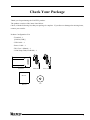
4Port RS-232C Interface Module for USB
COM-4(USB)
User’s Manual
CONTEC CO.,LTD.
Check Your Package
Thank you for purchasing the CONTEC product.
The product consists of the items listed below.
Check, with the following list, that your package is complete. If you discover damaged or missing items,
contact your retailer.
Product Configuration List
- Terminal…1
[COM-4(USB)]
- USB Cable…1
- Power Cable…1
- This User’s Manual…1
- COM Setup Disk(CD-ROM)…1
Terminal
USB Cable
Power Cable
Manual
Manual
COM-4(USB)
CD
i
Copyright
Copyright 1999 CONTEC CO., LTD. ALL RIGHTS RESERVED
No part of this document may be copied or reproduced in any form by any means without prior written
consent of CONTEC CO., LTD.
CONTEC CO., LTD. makes no commitment to update or keep current the information contained in this
document. The information in this document is subject to change without notice.
All relevant issues have been considered in the preparation of this document. Should you notice an
omission or any questionable item in this document, please feel free to notify CONTEC CO., LTD.
Regardless of the foregoing statement, CONTEC assumes no responsibility for any errors that may
appear in this document or for results obtained by the user as a result of using this product.
Trademarks
MS, Microsoft, Windows, Windows NT and MS-DOS are trademarks of Microsoft Corporation. Other
brand and product names are trademarks of their respective holder.
ii
COM-4(USB)
Table of Contents
Check Your Package.................................................................................................................................... i
Copyright ..................................................................................................................................................... ii
Trademarks .................................................................................................................................................. ii
Table of Contents.......................................................................................................................................iii
1.
BEFORE USING THE PRODUCT
1
About the Terminal..................................................................................................................................... 1
Features................................................................................................................................................. 1
Support Software ................................................................................................................................. 2
Cable & Connector (Option) ............................................................................................................. 3
Customer Support ....................................................................................................................................... 4
Web Site................................................................................................................................................ 4
Limited Three-Year Warranty ................................................................................................................... 4
How to Obtain Service ............................................................................................................................... 4
Liability........................................................................................................................................................ 4
Safety Precautions....................................................................................................................................... 5
Safety Information............................................................................................................................... 5
Handling Precautions .......................................................................................................................... 5
Environment ......................................................................................................................................... 6
Inspection ............................................................................................................................................. 6
Storage .................................................................................................................................................. 6
2.
SETUP
7
What is Setup?............................................................................................................................................. 7
Using the Terminal under Windows.................................................................................................. 7
Step 1 Setting the Hardware ...................................................................................................................... 8
Parts of the Terminal and Factory Defaults...................................................................................... 8
Setting the ID Switch .......................................................................................................................... 9
LED Indicators................................................................................................................................... 10
Connecting the USB Cable............................................................................................................... 10
Power Supply ..................................................................................................................................... 11
Installation Conditions ...................................................................................................................... 12
Step 2 Installing the Hardware ................................................................................................................ 13
Turning on the PC.............................................................................................................................. 13
Setting with the Add New Hardware Wizard................................................................................. 14
The check method of the completion of hardware installation .................................................... 15
Step 3 Initializing the Software............................................................................................................... 16
For use under Windows XP, Windows 2000.................................................................................. 16
For use under Windows Me, Windows 98 or Windows 95 .......................................................... 17
COM-4(USB)
iii
Step 4 Checking Operations with the Diagnosis Program ................................................................... 18
What is the Diagnosis Program?...................................................................................................... 18
Check Method.................................................................................................................................... 18
Using the Diagnosis Program........................................................................................................... 19
Setup Troubleshooting ............................................................................................................................. 21
Symptoms and Actions ..................................................................................................................... 21
If your problem cannot be resolved................................................................................................. 21
3.
EXTERNAL CONNECTION
23
Interface connectors.................................................................................................................................. 23
Types of Cable and Example Connections ............................................................................................ 24
4.
FUNCTIONS
25
Communication Function......................................................................................................................... 25
Serial Data Transmission.................................................................................................................. 25
RS-232C Control Lines..................................................................................................................... 25
Send and Receive Data Buffers........................................................................................................ 25
Setting the Baud Rate........................................................................................................................ 26
5.
ABOUT SOFTWARE
27
About Sample programs........................................................................................................................... 27
Uninstalling the driver software.............................................................................................................. 28
CD-ROM Directory Structure ................................................................................................................. 28
6.
ABOUT HARDWARE
29
Hardware specification............................................................................................................................. 29
Attachment Hole Positions ...................................................................................................................... 30
iv
COM-4(USB)
1. Before Using the Product
1. Before Using the Product
This chapter provides information you should know before using the product.
About the Terminal
This product is an RS-232C communication terminal with a USB interface that can be used to perform
RS-232C serial communications with external devices.
Each terminal has four RS-232C serial ports.
You can use the standard COM driver software (COM Setup Disk) supplied with the terminal to access
the serial ports as standard Windows COM ports.
To use this terminal, you must install the appropriate CONTEC driver software.
Features
-
Maximum communication speed = 115,200bps.
-
The baud rate for each channel can be set independently.
-
Each channel is equipped with separate 4K-byte FIFO buffers for transmit and receive.
-
A maximum of 16 terminals can be installed as configured in the range COM1 to COM64.
-
Driver software is supplied to allow the serial ports to be used as standard Windows COM ports.
-
Uses the same easy-to-use 9-pin D-SUB connectors as a PC.
COM-4(USB)
1
1. Before Using the Product
Support Software
You should use CONTEC support software according to your purpose and development environment.
Standard COM Driver Software COM Setup Disk COM Setup Disk (Bundled)
Under Windows, this software allows you to use the serial ports on the terminal as if they were standard
COM ports on the PC. You can add additional terminals up to a maximum of 64 COM ports.
The terminals can be used for all types of serial communications such as for remote access service (RAS) and
uninterruptible power supply (UPS) applications.
Under Windows, the serial ports can be accessed using the standard Win32 API communication routines (CreateFile( ),
WriteFile( ), ReadFile( ), and SetCommState( ), etc.) The serial ports are also compatible with the Visual Basic
communication control (MSComm).
< Operating environment >
OS
Windows XP, 2000, Me, 98 etc..
Base package of ActiveX components for measurement system development
ACX-PAC(W32)BP (Option)
"This is a set of useful Windows development tools for measurement systems and consists of a software
component library with ready-to-use samples which you can combine for easy programming.
The package contains components for controlling CONTEC I/O boards (PC cards). Features include
interface control for analog I/O, digital I/O, GPIB communications, and counter inputs, as well as X-Y
plotting and file storage support.
Check the CONTEC’s Web site for more information on this soft.
Advanced Package of ActiveX components for measurement system development
ACX-PAC(W32)AP (Option)
"Complements the ACX-PAC(W32)BP functions with additional components including graphics
(plotting, switches, and lamps, etc.) and mathematical and analysis tools.
Check the CONTEC’s Web site for more information on this soft.
2
COM-4(USB)
1. Before Using the Product
Cable & Connector (Option)
RS-232C Straight Cable with D-SUB9P (1.8m)
:
RSS-9M/F
RS-232C Cross Cable with D-SUB9P (1.8m)
:
RSC-9F
RS-232C Connection Conversion Straight Cable (25M→9F, 1.8m) :
RSS-25M/9F
RS-232C Connection Conversion Cross Cable (25F→9F, 1.8m)
:
RSC-25F/9F
D-SUB9P Male Connector Set (5 Pieces)
:
CN5-D9M
D-SUB9P Female Connector Set (5 Pieces)
:
CN5-D9F
*
Check the CONTEC’s Web site for more information on these options.
COM-4(USB)
3
1. Before Using the Product
Customer Support
CONTEC provides the following support services for you to use CONTEC products more efficiently and
comfortably.
Web Site
Japanese
English
Chinese
http://www.contec.co.jp/
http://www.contec.com/
http://www.contec.com.cn/
Latest product information
CONTEC provides up-to-date information on products.
CONTEC also provides product manuals and various technical documents in the PDF.
Free download
You can download updated driver software and differential files as well as sample programs available in
several languages.
Note! For product information
Contact your retailer if you have any technical question about a CONTEC product or need its price,
delivery time, or estimate information.
Limited Three-Year Warranty
CONTEC Terminals are warranted by CONTEC CO., LTD. to be free from defects in material and
workmanship for up to three years from the date of purchase by the original purchaser.
Repair will be free of charge only when this device is returned freight prepaid with a copy of the original
invoice and a Return Merchandise Authorization to the distributor or the CONTEC group office, from
which it was purchased.
This warranty is not applicable for scratches or normal wear, but only for the electronic circuitry and
original terminals. The warranty is not applicable if the device has been tampered with or damaged
through abuse, mistreatment, neglect, or unreasonable use, or if the original invoice is not included, in
which case repairs will be considered beyond the warranty policy.
How to Obtain Service
For replacement or repair, return the device freight prepaid, with a copy of the original invoice. Please
obtain a Return Merchandise Authorization Number (RMA) from the CONTEC group office where you
purchased before returning any product.
*
No product will be accepted by CONTEC group without the RMA number.
Liability
The obligation of the warrantor is solely to repair or replace the product. In no event will the warrantor
be liable for any incidental or consequential damages due to such defect or consequences that arise from
Safety Precautions
Understand the following definitions and precautions to use the product safely.
4
COM-4(USB)
1. Before Using the Product
Safety Precautions
Understand the following definitions and precautions to use the product safely.
Safety Information
This document provides safety information using the following symbols to prevent accidents resulting in
injury or death and the destruction of equipment and resources. Understand the meanings of these labels
to operate the equipment safely.
DANGER
DANGER indicates an imminently hazardous situation which, if not avoided, will
result in death or serious injury.
WARNING
WARNING indicates a potentially hazardous situation which, if not avoided, could
result in death or serious injury.
CAUTION
CAUTION indicates a potentially hazardous situation which, if not avoided, may
result in minor or moderate injury or in property damage.
Handling Precautions
DANGER
Do not use the product where it is exposed to flammable or corrosive gas. Doing so may result in an
explosion, fire, electric shock, or failure.
CAUTION
-
There are switches on the terminal that need to be set in advance.
Please check these before turning on the power.
-
Do not strike or bend the terminal. Doing so could damage the terminal.
Otherwise, the terminal may malfunction, overheat, cause a failure or breakage.
-
If you notice any strange odor or overheating, please unplug the power cord immediately.
-
Don not place objects on top of or next to the terminal in such a way that they obstruct the air vents.
-
Do not install or remove the terminal to or from the slot while the computer's power is turned on.
Otherwise, the terminal may malfunction, overheat, or cause a failure.
Doing so could cause trouble. Be sure that the personal computer or the I/O expansion unit power is
turned off.
-
Make sure that your PC or expansion unit can supply ample power to all the terminals installed.
Insufficiently energized terminals could malfunction, overheat, or cause a failure.
-
The specifications of this product are subject to change without notice for enhancement and quality
improvement.
Even when using the product continuously, be sure to read the manual and understand the contents.
COM-4(USB)
5
1. Before Using the Product
Environment
Use this product in the following environment. If used in an unauthorized environment, the terminal
may overheat, malfunction, or cause a failure.
Operating temperature
0 to 50°C
Humidity
10 to 90%RH (No condensation)
Corrosive gases
None
Floating dust particles
Not to be excessive
Inspection
Inspect the product periodically as follows to use it safely.
- The connector and cable by the side of
a terminal should be connected correctly.
- Ensure the air vents are free of dust or other obstructions.
Storage
When storing this product, keep it in its original packing form.
(1) Put the terminal in the storage bag.
(2) Wrap it in the packing material, then put it in the box.
(3) Store the package at room temperature at a place free from direct sunlight, moisture, shock,
vibration, magnetism, and static electricity.
6
COM-4(USB)
2. Setup
2. Setup
This chapter explains how to set up the terminal.
What is Setup?
Setup means a series of steps to take before the product can be used.
Different steps are required for software and hardware
The setup procedure varies with the OS and applications used.
Using the Terminal under Windows
This section describes the setup procedure to be performed before you can start developing application
programs for the terminal using the bundled CD-ROM “Standard COM Driver Software COM Setup Disk”.
Taking the following steps sets up the software and hardware. You can use the diagnosis program later
to check whether the software and hardware function normally.
Step 1 Setting the Hardware
Step 2 Installing the Hardware
Step 3 Initializing the Software
On the CD-ROM, refer to the \PCI\Readmee.txt file and the installation instructions files for each OS
located in the \PCI\InstDoc.
If Setup fails to be performed normally, see the “Setup Troubleshooting” section at the end of this
chapter.
CAUTION
Please note that Windows NT and Windows 95 versions earlier than OSR2.x are not supported.
On Windows 95 (OSR2.x), the driver software will not work correctly if the USB patch file is not
installed. Please refer to the manuals for your OS or PC for details about the USB patch file.
Please note that suspend(standby)/resume are not supported. Please setting power options for your
PC.
COM-4(USB)
7
2. Setup
Step 1 Setting the Hardware
This section describes how to setup the terminal and connect it to your PC.
The terminal has a number of switches that must be set before use.
Always check these settings before connecting the USB cable.
The default factory setting may be used. You can change the settings later if necessary.
Parts of the Terminal and Factory Defaults
Figure 2.1. show the names of major parts on the terminal.
Note that the switch setting shown below is the factory default.
Power supply connector
Power supply switch
Interface connectors(CN1 to CN4)
2
3
4
ID
1
USB connector
POWER
RX
LINK
TX
1
2
3
4
ID switch
LED indicator
Figure 2.1. Component Locations
8
COM-4(USB)
2. Setup
Setting the ID Switch
If you install two or more terminals on one personal computer, assign a different ID value to each of the
terminals to distinguish them.
The ID Switch can be set from 0 to Fh to identify up to sixteen terminals.
If only one terminal is used, the original factory setting (ID Switch = 0) should be used.
Setting Procedure
The ID is set using the rotary switch on the side of the terminal. Turn the switch to the desired setting.
The figure below shows the rotary switch set to ID 0.
ID
2
BCDE
A
3 4 56
ID
7 9
F01
Factory default setting :
(Board ID = 0)
Figure 2.2. ID Switch Settings
CAUTION
Reboot the PC after changing the ID switch setting.
If using an external power supply, also turn the power switch off and then on again.
COM-4(USB)
9
2. Setup
LED Indicators
The LEDs on the front panel indicate the power, USB port data link, and RS-232C port send/receive
statuses.
POWER
RX
LINK
TX
1
2
3
4
Figure 2.3. LED Indicators
Table 2.1. LED Indicators
LED Name
POWER(green)
LINK(green)
RX-1, 2, 3, 4
(green)
TX-1, 2, 3, 4
(yellow)
LED Indication
Illuminated … Power ON
Not Illuminated … Power OFF
Illuminated … USB port connection OK
Not Illuminated … USB port connection down or not connected
Flashing … RS-232C port data reception in progress *1
Not Illuminated … No data being received,or not connected
(1, 2, 3, and 4 correspond to the RS-232C port connector numbers.)
Flashing … RS-232C port data Transmission in progress *1
Not Illuminated … No data being transmitted,or not connected
(1, 2, 3, and 4 correspond to the RS-232C port connector numbers.)
*1 Note that the LEDs flash differently depending on the baud rate.
Connecting the USB Cable
Connect the terminal to the PC using the USB cable. You can also connect the terminal via a USB hub.
ID
Connect to USB
port on PC
Connect to USB port
on terminal
USB cable
Figure 2.4. Connecting the USB Cable
10
COM-4(USB)
2. Setup
Power Supply
If you want to use an external power supply, connect 100 VAC to the power supply connector and turn
on the power switch. Enabling the USB bus power is also possible without using the external power
supply. When using the bus power hub, be sure to use the power from COM-4(USB).
1
3
2
4
Plug into power
supply connector
ON
OFF
~~~
~~~~~~~
Power cable
Plug into 100VAC socket
Figure 2.5. Power Supply
CAUTION
If the host controller type for the USB port is OpenHCD, use the external power supply (self power)
when installing the COM-4(USB). On completing the installation, you can use the COM-4(USB)
without using the external power (that is, bus powered). If the host controller type is Universal, you
can install it using the bus power. Identify the host controller type using the following procedure.
(1) Select [System] from [Control Panel] and open [Device Manager].
(2) Double-click the [Universal Serial Bus Controller] folder.
(3) A type for the host controller type will be displayed for review.
COM-4(USB)
11
2. Setup
Installation Conditions
The following describes points to note when installing the terminal.
If locating the terminal on a desktop, place on a stable and level base and ensure there is sufficient space
around the terminal.
50mm
50mm
50mm
Air vents
50mm
Figure 2.6. Installation Conditions
CAUTION
-
The two circled parts of the terminal shown above are air vents. Do not place any objects on these
vents.
-
Holes are provided on the rear panel for wall mounting. Please obtain your own screws or other
fasteners if mounting the terminal on a wall. Mounting screws are not available from CONTEC.
12
COM-4(USB)
2. Setup
Step 2 Installing the Hardware
Under Windows, information about the terminal needs to be detected by the OS. This is called hardware
installation.
When using multiple terminals, install one at a time and complete setup for the previous terminal before
starting to install the next terminal.
Turning on the PC
(1) When using an external power supply, turn the power switch on after plugging the power cable into
the 100VAC supply.
(2) Connect the USB cable to the USB ports on the terminal and PC.
(3) Turn on the power to the PC. It is also OK to turn on the power before performing steps (1) and (2).
COM-4(USB)
13
2. Setup
Setting with the Add New Hardware Wizard
(1) The “Add New Hardware Wizard” will be started.
Select “Install from a list or specific location”, then click on the [Next] button.
(2)
Specify that folder on the CD-ROM which contains the setup information (INF) file to register the
terminal.
- Source folder
Windows XP, 2000
\USB\Win2000
Windows Me, 98
\USB\Win98
Windows 95
\USB\Win95
14
COM-4(USB)
2. Setup
CAUTION
In Windows XP, the Hardware Wizard displays the following alert dialog box when you have
located the INF file. This dialog box appears, only indicating that the relevant driver has not passed
Windows Logo testing, and it can be ignored without developing any problem with the operation of
the terminal.
In this case, click on the [Continue Anyway] button.
(3) Installation of the "Communication Port" starts next. If prompted for a file by the OS, specify the
location of the setup information (INF) file, as described above.
You have now finished installing the hardware.
The check method of the completion of hardware installation
(1) Select "System" from "Control Panel" and open [Device Manager].
(2) Check that the names of the terminals you are using are registered correctly in the [USB controller]
(or [Universal Serial Bus Controller])folder.
(3) Similarly, confirm that the COM ports have been added in the [Ports] folder.
COM-4(USB)
15
2. Setup
Step 3 Initializing the Software
This assigns COM ports to the serial ports on the terminal. You can also change a previously assigned
COM port number to a different number.
For use under Windows XP, Windows 2000
On Windows XP and Windows 2000, the COM ports are already assigned by the hardware installation
step. Run Device Manager as described below if you wish to view or modify the COM port settings.
Start Device Manager
(1) Select "System" from "Control Panel" and start [Device Manager].
(2) Check that the new COM ports are displayed in the [Ports] folder.
Updating the Settings
(1) If you wish to change a port number, open the properties page for the port and click the
[Advanced…] button under [Port Settings].
(2) Use the [COM Port Number] combo box to modify the COM port number.
You have now finished installing the initial setting of Software.
16
COM-4(USB)
2. Setup
For use under Windows Me, Windows 98 or Windows 95
Invoking API-TOOL Configuration
(1) Run \USB\Config\Config.exe from the supplied CD-ROM.
(2) Check that [COM-DRV Setting] appears on the screen.
If a different driver name appears, execute [Tools] - [COM-DRV].
(3) Double click on the terminal type name that is already displayed on the screen and modify the COM
port number and related settings.
Updating the Settings
(1) Select “Save settings to registry…” from the “File” menu.
(2) After rebooting, the registered COM ports are now able to be used as standard COM ports.
You have now finished installing the initial setting of Software.
COM-4(USB)
17
2. Setup
Step 4 Checking Operations with the Diagnosis
Program
Use the diagnosis program to check that the terminal and driver software work normally, thereby you can
confirm that they have been set up correctly.
What is the Diagnosis Program?
These programs perform some simple checks on the terminal operation. Two programs are provided.
Terminal program (CTstCom.exe)
Data entered from the keyboard is sent directly from the port. The function of the program is equivalent
to the Hyper Terminal program provided with Windows.
Serial Communications Diagnostic Program (CommChk.exe)
Performs actual communications and indicates whether the results are correct or not (error).
The following describes the procedure for testing using the serial communications diagnostic program
(CommChk.exe).
Check Method
Obtain an RS-232C crossed cable or a loopback connector. If using a loopback connector, you can
perform the check using a single COM port. The figure below shows the wiring connections for a
loopback connector.
Wiring connections for a loopback connector
TxD 3
RxD 2
RTS 7
CTS 8
DTR 4
DSR 6
18
COM-4(USB)
2. Setup
Using the Diagnosis Program
Starting the Diagnosis Program
Run [\Utility\CommChk\CommChk.exe] from the supplied CD-ROM.
Communication Settings
COM Setup:
Specify the number of the COM port you wish to test.
If connecting two COM ports via a cross cable, specify the respective COM ports in
[Device1] and [Device2].
When performing loopback communications on a single COM port, set the same port
number in both [Device 1] and [Device 2].
Communication Settings: Specify the [Bits / Second], [Data bits] and other settings you wish to use.
COM-4(USB)
19
2. Setup
Start test
Click the [Start] button to start the test using the specified conditions.
View test result
The test result is displayed in the [Message] window.
A successful completion message appears if the test completed OK.
20
COM-4(USB)
2. Setup
Setup Troubleshooting
Symptoms and Actions
If the terminal is not detected when you install the hardware.
If the USB port uses an OpenHCD type host controller, use the external power supply (self-power) when
installing the COM-4(USB). Once installed, you can use the terminal without the external power supply
(bus power).
If the USB port uses a "Universal" type host controller, you can use bus power even when installing.
You can determine which type of host controller you have as follows:
(1) From [Control Panel], select [System] and open [Device Manager].
(2) Double click on the [Universal Serial Bus Controller] folder.
(3) The type of host controller being used is displayed.
No response when installing the hardware [Windows 95]
If using Windows 95, check that you have an OSR2.x version. USB devices are not supported by
Windows 95 versions earlier than OSR2.x. You can check the version as follows.
(1) From [My Computer], open [Control Panel].
(2) Double click on [System] to open the [System Properties] window.
(3) Check the number displayed next to "System" on the [Information] page.
System:
Microsoft Windows 95
4.00.950C
If this number is 4.00.950 B or 4.00.950 C, you have an OSR2.x version OS and USB devices should
be able to be used.
USB devices cannot be used if the number is 4.00.950 or 4.00.950 a.
Even on OSR2.x version OSs, USB devices will not work correctly if the USB patch file is not installed.
Please refer to the manuals for your OS or PC for details about the USB patch file.
The device settings do not change when the ID switch setting is modified.
Reboot the system after changing the ID switch setting. If using an external power supply, also turn the
power switch off and then on again.
Unplugging and then reconnecting the terminal causes the COM port numbers to change
[Windows Me, 98, 95]
Immediately after installation, the COM port numbers used by the terminal are variable. Therefore, after
installing the terminal, use the API-TOOL configuration program (CONFIG.EXE) to set the COM port
numbers. After this, the serial ports on the terminal will always be assigned back to the same COM port
numbers if you unplug and then reconnect the terminal.
If your problem cannot be resolved
Contact your retailer.
COM-4(USB)
21
2. Setup
22
COM-4(USB)
3. External Connection
3. External Connection
This chapter describes the interface connectors on the terminal.
Check the information available here when connecting an external device.
Interface connectors
Use the interface connectors on the terminal to connect to external devices.
Thumb screw : UNC#4-40(inch screw)
1
5
1
1
6
CN1
9
6
CN2
5 1
5
2
3
9
6
CN3
9
1
5
4
6
CN4
9
- Connector used
DELC-J9PAF-20L9 equivalent (mfd. by JAE, Male)
- Applicable connectors
17JE-13090-02(D8C) (mfd. by DDK, Female)
CN5-D9F (mfd. by CONTEC, Female) (Five connector set)
Figure 3.1. Interface Connectors
DCD(Data Carrier Detect)
RxD (Receive Data)
TxD (Transmit Data)
DTR (Data Terminal Ready)
SG (Signal Ground)
1
2
6
3
7
4
8
5
9
RI (Ring Indicator)
CTS (Clear to Send)
RTS (Request to Send)
DSR (Data Set Ready)
Figure 3.2. Interface Connector Pin Assignment
Cable (Option)
RS-232C Straight Cable with D-SUB9P (1.8m)
RSS-9M/F
RS-232C Cross Cable with D-SUB9P (1.8m)
RSC-9F
RS-232C Connection Conversion Straight Cable (25M→9F, 1.8m)
RSS-25M/9F
RS-232C Connection Conversion Cross Cable (25F→9F, 1.8m)
RSC-25F/9F
COM-4(USB)
23
3. External Connection
Types of Cable and Example Connections
When using an RS-232C interface, different cables are required depending on the type of device to
which you are connecting (computer or modem, etc.). Check the requirements of the external device and
select either a straight-through or crossed (null modem) cable as appropriate. If special treatment of the
signal lines in the connector is required, ensure that this is done in accordance with the specifications.
TxD
TxD
(Transmit Data)
RxD
RxD
(Receive Data)
RTS
RTS
(Request to Send)
CTS
CTS
(Clear to Send)
DTR
DTR
(Data Terminal Ready)
DSR
DSR
(Data Set Ready)
SG
SG
(Signal Ground)
External device
Figure 3.3. Example Connection to a Modem (Straight cable)
TxD
TxD
RxD
RxD
RTS
RTS
CTS
CTS
DTR
DTR
DSR
DSR
SG
SG
External device
Figure 3.4. Example Connection to a PC (Cross cable)
TxD
TxD
RxD
RxD
RTS
RTS
CTS
CTS
DTR
DTR
DSR
DSR
SG
SG
External device
Figure 3.5. Example Connection to a Device
24
COM-4(USB)
4. Functions
4. Functions
This section describes the functions of the terminal.
Communication Function
Serial Data Transmission
Sends and receives data in accordance with the RS-232C standard.
The baud rate for each channel can be set independently in the range 15 to 115,200bps by software.
RS-232C Control Lines
All ports include the RTS, CTS, DTR, and DSR control lines.
The lines can be controlled or monitored by software from the application
Send and Receive Data Buffers
Each channel has a separate 4-byte send and 4-byte receive buffer. These are useful for high speed
communications and to reduce the load that the system places on the CPU.
COM-4(USB)
25
4. Functions
Setting the Baud Rate
The baud rate is set by specifying the divide register value (divisor).
Baud Rate: 15 to 115,200bps
Table 4.1 lists the divisor settings for common baud rates when using the COM Setup Disk.
Table 4.1. Example Settings for Common Baud Rates
Baud Rate
Divisor
Setting Baud Rate
Divisor
Error
Setting Baud Rate
Divisor
Error
Setting
Error
15
61440
-
1200
768
-
14400
64
-
50
18432
-
1800
512
-
19200
48
-
75
12288
-
2000
461
0.04
28800
32
-
110
8378
0.0022
2400
384
-
38400
24
-
134.5
6852
0.0006
3600
256
-
57600
16
-
150
6144
-
4800
192
-
76800
12
-
300
3072
7200
128
-
115200
8
-
600
1536
9600
96
-
Use the formula below if you want to set a baud rate other than those listed in Table 4.1. A baud rate can
only be set if the divisor calculated by the formula is an integer. Any digits after the decimal point
indicate that the baud rate cannot be used.
921600 ÷ Desired baud rate = (Divisor)Division register setting value
Ex.) 921600 ÷ 9600bps = 96 (As the result is an integer, this baud rate can be set.)
921600 ÷ 64000bps = 14.4 (As the result contains a fractional part, this baud rate cannot be set.)
26
COM-4(USB)
5. About Software
5. About Software
The "Standard COM Driver Software COM Setup Disk" from the supplied CD-ROM provides the
following functions.
-
Operation under Windows and Linux.
-
The serial ports can be used in the same way as the standard COM ports on the PC.
-
The terminals can be used for all types of serial communications such as for remote access service
(RAS) and uninterruptible power supply (UPS) applications.
-
The serial ports can be accessed using the standard Win32 API communication routines
(CreateFile( ), WriteFile( ), ReadFile( ), and SetCommState( ), etc.)
-
The serial ports are also compatible with the Visual Basic communication control (MSComm).
Refer to the \PCI\Readmee.txt files on the CD-ROM for details.
About Sample programs
Sample programs are provided in the \Samples folder on the CD-ROM. Use the sample programs for
reference and testing when developing software.
Visual Basic sample programs
(1) Transmit/Receive sample
-
Sends data entered from the keyboard and displays received data on the screen.
-
Source folder: \Samples\Vb folder
Visual C++ sample programs
(1) Transmit sample
-
Sends data entered from the keyboard. Execute from the command prompt.
-
Source folder: \Samples\Vc\Comsend.c file
(2) Receive sample
-
Displays received data on the screen.
-
Source folder: \Samples \Vc\Comread.c file
COM-4(USB)
27
5. About Software
Uninstalling the driver software
Use the following procedure to uninstall a previously installed COM Setup Disk.
(1) Run [Device Manager] from [Control Panel] - [System].
(2) Use the Delete key to delete the [CONTEC COM-4(USB) Serial Ports] entry that appears under
[USB Controller] (or [Universal Serial Bus Controller]).
Next, use the Delete key to delete the [CONTEC COM-4(USB)] entry.
[CONTEC COM-4(USB) Serial Ports] is only present on Windows Me, 98, and 95.
(3) Start Explorer.
(4) Select [Tools] - [Folder Options].
(5) Select the [View] tab.
(6) Select [Show all folders and files] (or [Show all files]), then click OK.
(7) Right click on the \Winnt\Inf folder (or \Windows\Inf folder) and run [Search].
(8) Enter COM-4(USB) in the [Containing text] field then click [Start Search].
Do not enter anything in the [File or folder name] (or [Named]) field.
(9) Delete all files found by the search.
(10)Delete the driver file corresponding to the OS you are using.
Windows XP:
Com4usb.sys and Com4port.sys in the \Windows\system32\drivers folder
Windows 2000:
Com4usb.sys and Com4port.sys in the \Winnt\system32\drivers folder
Windows Me/98/95: Com4enum.vxd, Com4usb.vxd and Com4port.sys in the \Windows\system
folder
CD-ROM Directory Structure
\
|–
|–
|–
|–
|
|
|–
|
|
|
|
|
|–
Linux
PCCARD
PCI
Samples
|– VB
|– VC
USB
|– Config
|– InstDoc
|– Win2000
|– Win95
|– Win98
UTILITY
|– CommChk
|– CTstCom
28
Linux device driver (for PCI boards and PC cards only)
PC card related files
PCI board related files
Various sample programs
Sample program for Visual Basic
Sample program for Visual C++
USB related files
Configuration utilities
Installation instructions for each OS.
Device driver and INF file for Windows XP/2000.
Device driver and INF file for Windows 95OSR2.
Device driver and INF file for Windows Me/98.
Various utilities
Self diagnostic program (Loopback communication test)
Self diagnostic program (Terminal utility)
COM-4(USB)
6. About Hardware
6. About Hardware
This chapter provides hardware specifications and hardware-related supplementary information.
Hardware specification
Tables 6.1 list the terminal specifications.
Table 6.1. Specification
Item
Specification
Number of channels
4ch
Interface type
RS-232C
Transfer method
Asynchronous serial transfer
Baud rate
15 to 115,200bps *1 *2
Data length
5, 6, 7, 8 bits
Parity check
Even, Odd, Non-parity *1
Buffer size
4KByte send and 4KByte receive for each channel
Controller chip
16C654 or equivalent
RS-232C Connecting
15m within
1, 1.5, 2 stop bits *1
distance
USB transfer speed
12Mbps(full speed mode)
Max. length of USB signal 5m
cable
power supply
Either self-power or bus-power can be used. *3
Power consumption
5VDC 210mA (Max.)
Operating temperature
0 to 50°C, 10 to 90%RH(No condensation)
Dimension (mm)
140.0(L) x 232.0(H) x 33.5(H)
Weight
420gExcluding cable)
*1
These items can be set by software.
*2
Data transmission at high speed may not be performed normally depending on the environment
including the type of status of connected material of cable and environment.
*3
If using a bus-power hub, use self-power for the COM-4(USB).
COM-4(USB)
29
6. About Hardware
Attachment Hole Positions
The figure below shows the locations of the attachment holes in plan view.
232
72
130
33
FRONT(LED Side)
4.5
81
140
8
8
REAR(COM Side)
[mm]
Figure 6.1. Attachment Hole Positions
30
COM-4(USB)
COM-4(USB)
User’s Manual
CONTEC CO.,LTD.
November 2003 Edition
3-9-31, Himesato, Nishiyodogawa-ku, Osaka 555-0025, Japan
Japanese http://www.contec.co.jp/
English http://www.contec.com/
Chinese http://www.contec.com.cn/
No part of this document may be copied or reproduced in any form by any means without prior written
consent of CONTEC CO., LTD.
[11262003]
[05121999]
[11262003_rev6]
Management No.
Parts No.
A-46-030
LZJ4121