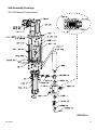
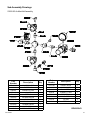
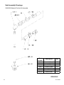
1
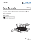
Operation
G2
Gel-Coat External Mix System
For use with Polyester Resin and Gel-Coat
Part 21990-00
Maximum fluid working pressure:
1300 psi. (9 MPa, 90 bar)
Maximum air pressure:
100 psi. (0.7 MPa, 7 bar)
Important Safety Instructions
Read all warnings and instructions in
this manual. Save these instructions.
GC-1395G
ENG
Contents
Warnings
Warnings ............................................................................................................................................................
General Safety ...................................................................................................................................................
Introduction ........................................................................................................................................................ 3
5
6
Set-up
Set-up Instructions ............................................................................................................................................. Pressure Relief Instructions ...............................................................................................................................
Start-up Instructions ........................................................................................................................................... Shut-down Instructions ....................................................................................................................................... Daily Start-up Instructions .................................................................................................................................. Parts ...................................................................................................................................................................
Assembly Drawings ............................................................................................................................................
Sub-Assembly Drawings ....................................................................................................................................
7
9
10
13
14
15
16
19
Maintenance
Maintenance .......................................................................................................................................................
Accesories ..........................................................................................................................................................
23
24
Technical Data
Technical Data ..................................................................................................................................................
Graco Ohio Standard Warranty ................................................................................................... Graco Ohio Information ............................................................................................................. 28
30
30
N/A = Non Applicable
GC-1395G
Warnings
The following warnings are for the setup, use, grounding, maintenance, and repair of this equipment.
The exclamation point symbol alerts you to a general warning and the hazard symbol refers to procedurespecific risk. Refer back to these warnings. Additional, product-specific warnings may be found throughout the
body of this manual where applicable.
• See Important Safety Information - MEKP, Polyester Resins and Gel-Coats and Spraying and Lamination
Operations section of this manual.
Changing Materials
Changing Materials
WARNING
•
When changing materials, flush the equipment multiple times
to ensure
it is thoroughly
clean.
FIRE
AND EXPLOSION
HAZARD
•
prevent
and
explosion:
Always clean
thefire
fluid
inlet
strainers after flushing.
Flammable fumes, such as solvent and paint fumes, in work area can ignite or explode. To help
•
•
•
• Use equipment only in well ventilated area.
• Eliminate
all ignition
sources; for
such
as pilot lights, cigarettes, portable electric lamps, and plastic
Check with
your material
manufacturer
chemical
drop
cloths
(potential
static
arc).
compatibility.
• Keep work area free of debris, including solvent, rags and gasoline.
• Do not plug or unplug power cords, or turn power or light switches on or off when flammable
Most materials
useare
ISO
on the A side, but some use
fumes
present.
ISO on the
B
side.
• Ground all equipment in the work area. See Grounding instructions.
• Use only grounded hoses.
Epoxies•often
have
theofBgrounded
(hardener)
Hold
gunamines
firmly toon
side
pail when triggering into pail.
• If there
is static
or you
a shock, stop operation immediately. Do not use
side. Polyureas
often
have sparking
amines on
the feel
B (resin)
equipment until you identify and correct the problem.
side.
• Keep a working fire extinguisher in the work area.
PERSONAL PROTECTIVE EQUIPMENT
You must wear appropriate protective equipment when operating, servicing, or when in the
operating area of the equipment to help protect you from serious injury, including eye injury,
This section inhalation
is used with
somefumes,
RAM burns,
plates and
which
couldloss.
get pushed
out of the
drumsbut
of is
sealant.
of toxic
hearing
This equipment
includes
not limited to:
• Protective eyewear
• Clothing and respirator as recommended by the fluid and solvent manufacturer
• Gloves
• Hearing protection
Splatter Hazard
WARNING
TOXIC FLUID OR FUMES HAZARD
SPLATTER
Toxic fluids HAZARD
or fumes can cause serious injury or death if splashed in the eyes or on skin, inhaled, or
Hot
or toxic fluid can cause serious injury if splashed in the eyes or on skin. During blow off of platen,
swallowed.
• Read
MSDS’s
splatter
may
occur.to know the specific hazards of the fluids you are using.
Store
hazardous
in approved
containers,platen
and dispose
of it according to applicable
• • Use
minimum
airfluid
pressure
when removing
from drum.
•
guidelines.
Always wear impervious gloves when spraying or cleaning equipment.
Burn Hazard
For equipment used with heated material.
GC-1395G
WARNING
BURN HAZARD - Hot Surfaces
Equipment surfaces and fluid that’s heated can become very hot during operation. To avoid severe burns:
• Do not touch hot fluid or equipment.
Skin Injection Hazard
Use with high pressure equipment, generally equipment with pressure rating of 900 psi or higher. There
sions of this section. 1) manual guns, 2) UL-1450 compliant equipment 3) automatic guns,/dispense val
Warnings
tion valves, 4) heated hoses. Since the text contains mostly “Do not” statements, the symbols have lines
them.
WARNING
WARNING
SKIN
HAZARD
SKININJECTION
INJECTION
HAZARD - Basic
High-pressure fluid from gun, hose leaks, or ruptured components will pierce skin. This may look
High-pressure fluid from gun, hose leaks, or ruptured components will pierce skin. This may l
like just a cut, but it is a serious injury that can result in amputation. Get immediate surgical
a
cut, but it is a serious injury that can result in amputation. Get immediate surgical treatm
treatment.
point
gun
at anyone
at of
any
•• DoDo
notnot
point
gun at
anyone
or at anyorpart
thepart
body.of the body.
•• DoDo
notnot
put put
youryour
hand hand
over the
dispense
outlet. tip.
over
the spray
•• DoDo
notnot
stopstop
or deflect
leaks with
yourwith
hand,
body,
glove,body,
or rag.glove, or rag.
or deflect
leaks
your
hand,
•• Engage
trigger
lock
when not
Do not
spray
without
tipspraying.
guard and trigger guard installed.
•• Follow
Pressure
Relief
Procedure
in spraying.
this manual, when you stop spraying and before cleaning,
Engage trigger lock when not
checking, or servicing equipment.
•
Follow Pressure Relief Procedure in this manual, when you stop spraying and before c
checking, or servicing equipment.
MOVING PARTS HAZARD
SKIN
Use with
UL1450
Compliance
Moving INJECTION
parts can pinchHAZARD
or amputate- fingers
and other
body parts.
not aim
gun at,parts.
or spray any person or animal.
•DoKeep
clearthe
of moving
•• DoKeep
not operate
equipment
with
protective
covers
hands and other
body
partsguards
awayor
from
theremoved.
discharge. For example, do not try to sto
• Pressurized
equipment
can
start
without
warning.
Before
checking, moving, or servicing
any part of the body.
equipment, follow the Pressure Relief Procedure in this manual. Disconnect power or air
• supply.
Always use the nozzle tip guard. Do not spray without nozzle tip guard in place.
•
Use Graco nozzle tips.
•EQUIPMENT
Use caution
when
cleaning and changing nozzle tips. in the case where the nozzle tip clo
MISUSE
HAZARD
spraying,
follow
the
Pressure
Misuse can cause death or serious
injury. Relief Procedure for turning off the unit and relieving the
• Dobefore
not operate
the unitthe
when
fatigued
the influence of drugs or alcohol.
removing
nozzle
tiportounder
clean.
Fire and Explosion
Hazard
•• DoDo
notnot
exceed
thethe
maximum
working pressure
or temperature
the lowest rated
system
leave
unit energized
or under
pressure rating
whileofunattended.
When
the unit is not
component. See Technical Data in all equipment manuals.
off the unit and follow the Pressure Relief Procedure for turning off the unit.
• Use fluids and solvents that are compatible with equipment wetted parts. See Technical Data
• in High-pressure
sprayRead
is able
inject
toxins
into the body
andFor
cause
serious bodily injury.
all equipment manuals.
fluidto
and
solvent
manufacturer’s
warnings.
complete
Pressurized
Aluminum
Parts
Hazard
that injection
occurs,
get request
immediate
information
about your
material,
MSDS surgical
forms from treatment.
distributor or retailer.
•
Check
hoses
and
parts
for
signs
of
damage.
Replace
any damaged
hoses or parts.
• Check equipment daily. Repair or replace worn or damaged
parts immediately
with genuine
replacement
parts
only.parts only.
Use with equipment
pressurized
aluminum
Equipment
havereplacement
aluminum parts
thatoraren’t
pres
• manufacturer’s
Thiswith
system
is capable
of producing
XXXX
psi. Usemay
Graco
parts
accesso
Dorated
not alter
or modify equipment.
ized - check• with
engineering.
a minimum
of XXXX psi.
• Use equipment only for its intended purpose. Call your distributor for information.
•
Always engage the trigger lock when not spraying. Verify the trigger lock is functioning pr
• Route hoses and cables away from traffic areas, sharp edges, moving parts, and hot surfaces.
that
all connections
operating the unit.
•• DoVerify
not kink
or over
bend hoses or are
use secure
hoses to before
pull equipment.
•
Know
how
to
stop
the
unit
and
bleed
pressure
quickly. Be thoroughly familiar with the con
• Keep children and animals away from work area.
•
WARNING
Comply with all applicable safety regulations.
PRESSURIZED ALUMINUM PARTS HAZARD
PRESSURIZED
ALUMINUM PARTS HAZARD
Do not use 1,1,1-trichloroethane, methylene chloride, other halogenated hydrocarbon solvents or fluids
Do
not use
methylene
other
containing
such1,1,1-trichloroethane,
solvents in pressurized aluminum
equipment.chloride,
Such use can
causehalogenated
serious chemical hydrocarbon solvents or fluid
reaction and equipment
rupture, and
in death, serious
injury, and
property damage.
containing
such solvents
in result
pressurized
aluminum
equipment.
Such use can cause serious chemical
reaction and equipment rupture, and result in death, serious injury, and property damage.
Plastic Parts Cleaning Solvent Hazard
GC-1395G
Created for CEDs Texture Sprayer. May have use with other waterbase application equipment with plastic parts th
can be damaged by certain solvents.
Important Safety Information
Methyl Ethyl Ketone Peroxide (MEKP)
MEKP is among the more hazardous materials
found in commercial channels. Proper handling
of the “unstable (reactive)” chemicals presents a
definite challenge to the plastics industry. The
highly reactive property which makes MEKP
valuable to the plastics industry in producing the
curing reaction of polyester resins and gel-coats
also produces the hazards which require great care
and caution in its storage, transportation, handling,
processing and disposal.
Workers must be thoroughly informed of the hazards
that may result from improper handling of MEKP,
especially in regards to contamination and heat.
They must be thoroughly instructed regarding the
proper action to be taken in the storage, use and
disposal of MEKP and other hazardous materials
used in the laminating operation.
MEKP is flammable and potentially explosive,
as well as potentially damaging to the eyes and
skin.
Read material manufacturer’s warnings and
material MSDS to know specific hazards and
precautions related to MEKP.
Contaminated MEKP can become explosive.
Prevent contamination of MEKP with other materials, which includes, but is not limited to polyester
overspray, polymerization accelerators and promoters, and non-stainless metals. Even small amounts
of contaminates can make MEKP explosive. This reaction may start slowly, and gradually build-up heat,
which can accelerate until fire or an explosion result.
This process can take from seconds to days.
Heat applied to MEKP, or heat build-up from contamination reactions can cause it to reach what is
called its Self-Accelerating Decompisition Temperature (SADT), which can cause fire or explosion.
Spills should be promptly removed, so no residues
remain. Spillage can heat up to the point of selfignition. Dispose in accordance with manufacture’s
recommendation.
Store MEKP in a cool, dry and well-ventilated area
in the original containers away from direct sunlight
and away from other chemicals. It is strongly recommended that the storage temperature remain below
86° F (30° C). Heat will increase the potential for explosive decomposition. Refer to NFPA 432.
Keep MEKP away from heat, sparks and open
flames.
GC-1395G
Current catalysts are premixed and do not require
any diluents. GlasCraft strongly recommends that diluents not be used. Diluants add to the possibility of contaminates entering the catalyst system. Never dilute
MEKP with acetone or any solvent since this can produce an extremely shock-sensitive compound which
can explode.
Use only original equipment or equivalent parts
from GlasCraft in the catalyst system (i.e.: hoses, fittings, etc.) because a hazardous chemical reaction
Spraying
materials containing isocyanates creates
may result between substituted parts and MEKP.
potentially
mists,
vapors,
and atomized
To preventharmful
contact with
MEKP,
appropriate
personalparticulates.
protective equipment, including chemically impermeable gloves, boots, aprons and goggles are required
Read
material
manufacturer’s
for everyone
in the
work area. warnings and material
MSDS to know specific hazards and precautions
related to isocyanates.
Isocyanate Conditions
•
•
•
•
Polyester Resins and Gel-Coats
Prevent inhalation of isocyanate mists, vapors, and
atomized particulates by providing sufficient ventilation in the work area. If sufficient ventilation is not
available, a supplied-air respirator is required for
Sprayinginmaterials
containing
everyone
the work
area. polyester resin and
gel-coats creates potentially harmful mist, vapors and
atomized
particulates.
Prevent
inhalationappropriate
by providing perTo
prevent
contact with
isocyanates,
sufficient
ventilation
and the use
of respirators
in the
sonal
protective
equipment,
including
chemically
work area.
impermeable
gloves, boots, aprons, and goggles, is
Read
the material
manufacturer’s
and maalso
required
for everyone
in the warnings
work area.
terial MSDS to know specific hazards and precautions
related to polyester resins and gel-coats.
To prevent contact with polyester resins and gelcoats, appropriate personal protective equipment,
including chemically impermeable gloves, boots,
aprons and goggles are required for everyone in the
work area.
•
•
K
B
Material Self-ignition
To
we
an
Some materials may become self-igniting if applied
too
thickly. Read
manufacturer’s
warnings
Spraying
and material
Lamination
Operations
and material MSDS.
Fo
B
Moisture Sensitivity of
Remove all accumulations of overspray, FRP sandIsocyanites
ings, etc. from the building as they occur. If this waste
is allowed to
build are
up, spillage
of used
catalyst
more
likely
Isocyanites
(ISO)
catalysts
in istwo
component
to
start
a
fire.
foam and polyurea coatings. ISO will react with moisture
If cleaning
solvents
are required,
read material
(such
as humidity)
to form
small, hard,
abrasive crystals,
manufacture’s
warnings
and
material
MSDS
to know a film
which become suspended in the fluid.
Eventually
specific hazards and precautions. (GlasCraft recomwill form on the surface and the ISO will begin to gel,
mends that clean-up solvents be nonflammable.)
increasing in viscosity. If used, this partially cured ISO
will reduce performance and the life of all wetted parts.
GlasCraft recommends that you consult OSHA
The amount of film formation and rate of crystalliSections 1910.94, 1910.106, 1910.107 and NFPA
zation varies depending on the blend of ISO, the
No. 33, Chapter 16,17, and NFPA No. 91 for further
humidity, and the temperature.
guidance.
To prevent exposing ISO to moisture:
Som
abo
if ag
circ
Some materials may become self-igniting if applied
Grounding
too thickly. Read material manufacturer’s warnings
and material MSDS.
Moisture Sensitivity of
Isocyanites
This equipment needs to be grounded.
Isocyanites (ISO) are catalysts used in two component
Ground
dispense
gun through
to anmoisture
foam
andthe
polyurea
coatings.
ISOconnection
will react with
GlasCraft
approved
grounded
fluid
supply
hose.
(such as humidity) to form small, hard, abrasive crystals,
which become suspended in the fluid. Eventually a film
Check
localsurface
electrical
code
related
manuals
will
formyour
on the
and
theand
ISO
will begin
to gel,
for
detailed
grounding
instructions
of
all
equipment
in ISO
increasing in viscosity. If used, this partially cured
the
work
area.
will reduce performance and the life of all wetted parts.
NOTICE
To prevent cross-contamination of the equipment’s
wetted parts, never interchange component A (isocyanate) and component B (resin) parts.
Foam Resins with 245 fa
Blowing Agents
Some foam blowing agents will froth at temperatures
above 90°F (33°C) when not under pressure, especially
if agitated. To reduce frothing, minimize preheating in a
circulation system.
The amount of film formation and rate of crystallization varies depending on the blend of ISO, the
A grounding wire and clamp are provided,
humidity, and the temperature.
assembly p/n 17440-00 with all FRP equipment.
To prevent exposing ISO to moisture:
Rev. G 6/17/2008
21
GC-1395G
Moisture Sensitivity of
Isocyanites
Set-Up
1. Remove the pump inlet safety cap and drain the
testing oil into an open container. Before operating the material pump, flush thoroughly with a
clean suitable solvent to remove test fluid.
3.
Isocyanites (ISO) are catalysts used in two component
foam and polyurea coatings. ISO will react with moisture
(such
as humidity)
to form
hard, inlet
abrasive
2. Attach
clear pick-up
hosesmall,
to the pump
fitting crystals,
and
which
become
suspended
in
the
fluid.
Eventually
a film
tighten.
will form on the surface and the ISO will begin to gel,
increasing in viscosity. If used, this partially cured ISO
3. Attach
pick-up hose
to the
the pick-up
tube.
will
reduceclear
performance
and
life of all
wetted parts.
The amount of film formation and rate of crystallization varies depending on the blend of ISO, the
humidity, and the temperature.
GlasCraft uses a test fluid that may not be compatible
with
some gel-coats
resins.
Thus it is recommended
To
prevent
exposingorISO
to moisture:
that the test fluid be flushed from the Material Pump
Fluid Section.
Rev. G 6/17/2008
Pick-up Tube
2.
GC-1395G
S
a
if
c
also required for everyone in the work area.
Material
Self-ignition
Set-Up
4. Select a clean, dry air supply.
Some
materials
become
if on
applied
5.
Attach
a 3/8” ormay
larger
air hoseself-igniting
to the Air Inlet
the
Keep Components A and
B Separate
available, a supplied-air respirator is required for
everyone in the work area.
To prevent contact with isocyanates, appropriate personal protective equipment, including chemically
NOTICE
impermeable gloves, boots, aprons, and goggles, is
preventfor
cross-contamination
of the
equipment’s
alsoTo
required
everyone in the work
area.
wetted parts, never interchange component A (isocyanate)
and component
B (resin)
parts.
Whenever
flammable
or combustible
liquids
are transfered
Material Self-ignition
Foam Resins with 245 fa
Blowing Agents
•
K
B
from one container to another, both containers shall be
effectively bonded and grounded to dissipate static electricity.
For
further information see.....
NFPA 77, Recommended Practice on Static Electricity.
Fire and Explosion Hazard
Some foam blowing agents will froth at temperatures
Some
materials
may
self-igniting
if
applied
90°F
(33°C)
when
not
under
pressure,
especially
8. Fillabove
material
pump
lubebecome
cup with
proper
pump
lube.
tooifthickly.
Read
materialfrothing,
manufacturer’s
agitated.
To reduce
minimizewarnings
preheating in a
and
material
MSDS.
circulation
system.
Use with
high
equipment
with pressure
rating of 900 psi or higher. There are 2 ve
Isocyanites
(ISO)
arepressure
catalystsequipment,
used in twogenerally
component
sions
of
this
section.
1)
manual
guns,
2)
UL-1450
compliant
equipment
3) automatic guns,/dispense valves,/lubri
foam and polyurea coatings. ISO will react with moisture
tion
valves,
4)
heated
hoses.
Since
the
text
contains
mostly
“Do
not”
statements,
the symbols have lines through
(such as humidity)
to form
small,
hard,equipment,
abrasive crystals,
Use with
high
pressure
generally equipment with pressure rating of 900 psi or higher. There
them. suspended in the fluid. Eventually a film
which become
sions of this section. 1) manual guns, 2) UL-1450 compliant equipment 3) automatic guns,/dispense valS
a
will form on the surface and the ISO will begin to gel,
tion valves, 4) heated hoses. Since the text contains mostly “Do not” statements, the symbols have lines
i
increasing in viscosity. If used, this partially cured ISO
them.
reduce performance
c
will
and the life of all wetted parts.
Isocyanites (ISO) are catalysts used in two component
The amount of film formation and rate of crystalli- foam and polyurea coatings. ISO will react with moisture
zation varies depending on the blend of ISO, the (such as humidity) to form small, hard, abrasive crystals,
which become suspended in the fluid. Eventually a film
humidity, and the temperature.
It is suggested that a quick disconnect fitting not be used for will form on the surface and the ISO will begin to gel,
To
prevent
ISO
to moisture:
INJECTION
HAZARD
Basic
attaching
air.exposing
QuickSKIN
disconnect
fittings can
severely- limit
air increasing in viscosity. If used, this partially cured ISO
flow.
willorreduce
performance
life of
all wetted
parts.
High-pressure fluid from gun, hose leaks,
ruptured
componentsand
willthe
pierce
skin.
This may
look like j
tooyellow
thickly.
material
airRead
lock-out
valve. manufacturer’s warnings
and material MSDS.
Fire and Explosion Hazard
Moisture
Sensitivity
Skin Injection
Hazard of
Isocyanites
Skin Injection Hazard
Moisture Sensitivity of
Isocyanites
F
B
WARNING
WARNING
a cut, but
it is INJECTION
a serious injury
that can
result in amputation. Get immediate surgical treatment.
SKIN
HAZARD
- Basic
The amount of film formation and rate of crystalli• Do not point gun at anyone or at any partzation
of the body. depending on the blend of ISO, the
High-pressure fluid from gun, hose leaks, orvaries
ruptured components will pierce skin. This may l
• Do not put your hand over the spray tip. humidity, and the temperature.
Rev. G 6/17/2008
21
a cut, but it is a serious injury that can result in amputation. Get immediate surgical treatm
• Do not stop or deflect leaks with your
hand, body,
glove, or
rag.
GlasCraft
recommends
you
contact your material supplier
Before turning on main air, check
all
fittings,
making
certain
•
Do not point gun at anyone To
or at
any part
of the body.to moisture:
prevent
exposing
for their
recommendation
of a lubricant that will be suitable
• Do not
spray
without
tip before
guard air
and trigger
guard
installed.ISO
they are securely tightened.
should
be done
• ThisDo
not put
your hand
over the
spray
tip.
for use with your material.
•
Engage
trigger
lock
when
not
spraying.
or material of any kind is introduced
into stop
the system.
•
Do not
or deflect leaks with your hand, body, glove, or rag.
• Follow Pressure Relief Procedure in this manual, when you stop spraying and before cleaning,
•
Do not spray without tip guard and trigger guard installed.
checking, or servicing equipment.
Engage
trigger
lock to
when not spraying.
6. Attach Grounding Clamp•Assembly,
P/N
17440-00,
Rev. G 6/17/2008
•
Follow
Pressure
Relief
Procedure
this manual, when you stop spraying and before c
System. Use a convenient
Nut
and
Bolt
to
secure
Lug,
SKIN INJECTION HAZARD - Use with
UL1450inCompliance
P/N 13193-00, to slave pump.checking, or servicing equipment.
Do not aim the gun at, or spray any person or animal.
•
Keep hands and other body parts away from the discharge. For example, do not try to stop leaks w
any part of the body.
grounded rod or pipe. Do not aim the gun at, or spray any person or animal.
• Always use the nozzle tip guard. Do not spray without nozzle tip guard in place.
•
Keep hands and other body parts away from the discharge. For example, do not try to sto
• Use Graco nozzle tips.
any part of the body.
• Use caution when cleaning and changing nozzle tips. in the case where the nozzle tip clogs while
•
Always use the nozzle tip guard. Do not spray without nozzle tip guard in place.
spraying, follow the Pressure Relief Procedure for turning off the unit and relieving the pressure
•
Use Graco nozzle tips.
Attach Here
before removing the nozzle tip to clean.
•
Use caution when cleaning and changing nozzle tips. in the case where the nozzle tip cl
• Do not leave the unit energized or under pressure while unattended. When the unit is not in use, tu
spraying, follow the Pressure Relief Procedure for turning off the unit and relieving the
off the unit and follow the Pressure Relief Procedure for turning off the unit.
before removing the nozzle tip to clean.
• High-pressure spray is able to inject toxins into the body and cause serious bodily injury. In the ev
•
Do not leave the unit energized or under pressure while unattended. When the unit is not
that injection occurs, get immediate surgical treatment.
off the unit and follow the Pressure Relief Procedure for turning off the unit.
• Check hoses and parts for signs of damage. Replace any damaged hoses or parts.
•
High-pressure spray is able to inject toxins into the body and cause serious bodily injury.
• This system is capable of producing XXXX psi. Use Graco replacement parts or accessories that a
that injection occurs, get immediate surgical treatment.
rated a minimum of XXXX psi.
•
Check hoses and parts for signs of damage. Replace any damaged hoses or parts.
• Always engage the trigger lock when not spraying. Verify the trigger lock is functioning properly.
•
This system is TO
capable
of producing XXXX psi. Use Graco replacement parts or accesso
SLAVE PUMP
• Verify that all connections are secure before operating the unit.
rated a minimum of XXXX psi.
• Know how to stop the unit and bleed pressure quickly. Be thoroughly familiar with the controls.
•
Always
engage the trigger lock when not spraying. Verify the trigger lockGC-1395G
is functioning p
•
Verify that all connections are secure before operating the unit.
•
Know how to stop the unit and bleed pressure quickly. Be thoroughly familiar with the co
SKIN
INJECTION
HAZARD - Use with UL1450 Compliance
7. Securely attach Clamp, P/N
7749-00
to permanently
Pressure Relief Procedure
To relieve fluid and air pressures:
1. Push down Yellow slide valve, P/N 21402-00 to bleed
off air to system.
2. Open P/N 21228-00 on catalyst pump to recirculation
position.
3. Open P/N 21192-00 on bottom of material pump.
GC-1395G
Start-Up
7. (Formula Gun Only) Adjust the trigger air regulator
to 100 PSI (7 bar).
1. Pull and rotate Pivot knob
to disengage the catalyst drive
arm.
The trigger air should not exceed 100 PSI (7 bar).
2. Turn the catalyst slave
pump yellow ball valve
to the open position.
3. Hand prime the pump
until a steady stream of
catalyst flows back to the
bottle.
8. Remove Cap, Catalyst Ring, Spray Tip and Spacer
from the gun. (refer to gun manual)
4. Close the ball valve. Hand
stroke the pump until it
developes 30-40 PSI
(2-3 bar).
9. Trigger the Gun until a steady material stream
appears at the Nozzle Body. The material regulator
should initially be set not to exceed 10 PSI (0.7 bar).
5. Open the main air valve slowly.
Changing Materials
Changing Materials
•
When changing materials, flush the equipment multiple times to ensure it is thoroughly clean.
•
Always clean the fluid inlet strainers after flushing.
•
Check with your material manufacturer for chemical
compatibility.
•
10. Once a steady material stream is achieved,
release trigger and re-assemble all parts removed
from the gun.
Most materials use ISO on the A side, but some use
ISO on the B side.
6. Turn material• regulator
slowly clockwise until guage
Epoxies often have amines on the B (hardener)
indicates 10 PSIside.
(0.7Polyureas
bar). The
will cycle
oftenpump
have amines
on theslowly
B (resin)
and stall when the
pump
is
full
of
material.
side.
Cap, P/N LPA2-213, should be HAND TIGHTENED
ONLY. Never use a wrench or pliers to assemble, tighten
or remove this cap. If threads are clean and lubricated
Splatter Hazard
properly,
assembly
This section is used with some RAM plates which could get pushed
out ofhand
the drums
of sealant.and removal will not be a
problem. Use of wrenches or pliers will likely cause serve
damage to the threads and/or Gun Head.
WARNING
SPLATTER HAZARD
Hot or toxic fluid can cause serious injury if splashed in the eyes or on skin. During blow off of platen,
splatter may occur.
• Use minimum air pressure when removing platen from drum.
Do not exceed 10 PSI (0.7 bar) pressure on the Material
Regulator until steady material flow has been established.
10
Burn Hazard
For equipment used with heated material.
GC-1395G
• Most materials
ISO on
the A side, butasome
which become suspended
in the use
fluid.
Eventually
filmuse
on the
B side.
will form on the surfaceISO
and
the
ISO will begin to gel,
increasing in viscosity. If used, this partially cured ISO
• Epoxies often have amines on the B (hardener)
will reduce performance
the life
allamines
wetted
side.and
Polyureas
oftenof
have
on theparts.
B (resin)
Start-Up
side.
The amount of film formation and rate of crystallization varies depending on the blend of ISO, the
Follow step 12, if optional catalyst bottle is being used.
humidity, and the temperature.
11. Slowly increase resin pressure regulator until
desired spray pattern is achieved. (See Fig. 3)
Hazard
To prevent exposingSplatter
ISO to moisture:
This section is used with some RAM plates which could get pushed o
Typical Spray Pattern Development
13. Safely fill the Catalyst Supply Bottle, P/N LPA-165
(maximum two gallons) with preferred MEKP catalyst
to a minimum level at least one inch above the catalyst
bottle outlet fitting.
Rev. G 6/17/2008
(without Air Assist)
WARNI
STEP RESIN PATTERN PRESSURE
PRESSURE ADJUSTMENT
SPLATTER HAZARD
Hot or toxic fluid can cause serious injury if splashed in the
splatter may occur.
• Use minimum air pressure when removing platen from
________________________________
1
20 PSI
INCREASE
Remove Catalyst Bottle, P/N LPA-167-1, from Catalyst
Bottle Bracket, P/N LPA-169, for filling.
2
25 PSI
INCREASE
3
30 PSI
INCREASE
Bottle should beBurn
placedHazard
at or below waist-level for safe
filling.
For equipment used with heated material.
4
35 PSI*
CORRECT
Final pressure typically ranges from 30-45 PSI
(2.1-3.1 bar) depending on material used.
Fig. 3
Never fill Catalyst Bottle while mounted in Bracket as
personal injury from catalyst spillage could result.
WARNI
HAZARDuntil
- Hot all
Surfaces
14. Trigger the Gun into BURN
a container
the air is
Equipment
and fluidItthat’s
heated
purged from the resin
side ofsurfaces
the system.
may
be can become ve
• Do not
hot fluidPump
or equipment.
necessary to Hand stroke
thetouch
Catalyst
several
Wait until equipment/fluid
has cooled completely.
times while the gun •is triggered
to positively.
12. Slowly increase Air Assist Air Pressure Regulator
until tails disappear from spray pattern.
(See Fig. 4)
Typical Spray Pattern Development
(with Air Assist)
STEP AIR ASSIST PATTERN PRESSURE
ADJUSTMENT ADJUSTMENT
22
_________________________________
1
CLOSED
INCREASE
2
15 PSI
INCREASE
3
30 PSI
CORRECT
Final air assist adjustment is complete when tails are
elimated and a uniform spray pattern is achieved. Final
pressure typically ranges from 30-45 PSI
(2.1-3.1 bar) depending on material used.
Fig. 4
GC-1395G
11
Moisture Sensitivity of
Start-Up
Isocyanites
Material Self-ignition
B
Blowing
Agents
S
Moisture
Sensitivity of
Some foam blowing agents will froth at temperatures
a
above 90°F (33°C) when not under pressure, especially i
Isocyanites
if agitated. To reduce frothing, minimize preheating in a
should
be determined by the type of resin
release
the Trigger
and ISO
stop will
stroking
andsetting
material
MSDS.
foam and
polyurea
coatings.
reactPump
with Arm.
moisture (such
as humidity)
to form small, hard, abrasive crystals,
and
catalyst
being
used.
(such as humidity) to form small, hard, abrasive crystals, which become suspended
in the fluid. Eventually a film
which
suspended
in the
a film will form on the surface and the ISO will begin to gel,
16.become
Check and
make certain
thatfluid.
SprayEventually
Gun Material
20.
Re-adjust catalyst atomizing air pressure to approxiwill formand
onCatalyst
the surface
andactivate
the ISO
begin
gel,
Needles
atwill
exactly
theto
same
increasing
in viscosity. If used, this partially cured ISO
mately
PSI (2.8 bar).
increasing
time.in viscosity. If used, this partially cured ISO will reduce40performance
and the life of all wetted parts.
will reduce performance and the life of all wetted parts.
amount
of film
and at
rate
crystalli The
Failure
to activate
theformation
Catalyst Valve
theofGun
The amount of film formation and rate of crystalli- Isocyanites
zation
varies
depending
on
the
blend
of
ISO,
(ISO)
areiscatalysts
used
inintwo
when the
Pump
cycling will
result
an component
over- the
Catalyst Needle should never lead Material Needle as
zation varies depending on the blend of ISO, the foam and
humidity,
and
the
temperature.
polyurea coatings.
ISO Pump
will react
pressurization
of the Catalyst
and with
the moisture
a loss of Catalyst system prime could result.
humidity, and the temperature.
(such as
humidity)
to form
small,
hard, abrasive
crystals,
automatic
opening
on
the
Pressure
Relief
Valve.
To prevent exposing ISO to moisture:
which
become
suspended
in
the
fluid.
Eventually
a film
To
prevent
exposing
ISO
to
moisture:
17. Engage Catalyst drive arm to Material Pump.
will
the surface
andexamine
the ISOthe
will
begin to gel,
21. form
Whileon
triggering
the Gun,
atomized
increasing
viscosity.
If used,
this partially
catalystin
making
certain
it is properly
enteringcured
the ISO
Knob
will reduce
and the life of all wetted parts.
materialperformance
pattern.
Moisture Sensitivity of
Isocyanites
Rev. G 6/17/2008
Rev. The
G 6/17/2008
amount of film formation and rate of crystalli-
zation varies depending on the blend of ISO, the
humidity,
If catalyst pattern
too narrow...
and theistemperature.
... increase catalyst atomizing air in 5 PSI (0.3 bar)
To prevent
exposing ISO to moisture:
increments.
If catalyst pattern is too wide...
...decrease catalyst atomizing air in 5 PSI (0.3 bar)
increments.
Rev. G 6/17/2008
22. After all pressure adjustments have been complet-
18. Adjust catalyst atomizing air pressure to 25 PSI
ed, a final spray test should be made. Spray a test
shot sample on a clean piece of paper. This shot
should be approximately five feet in length. You
can now check for desired gel time and uniformity
of curing.
(1.7 bar). This pressure may be adjusted to
achieve desired catalyst droplet size.
12
c
Some materials may become self-igniting if applied
Isocyanites
(ISO)
are catalysts used in two component
circulation
system.
catalyst
calibration
as required. This
15. As soon
as are
all air
is eliminated,
tooRe-adjust
thickly.
Read
material
manufacturer’s
Isocyanites
(ISO)
catalysts
usedsimultaneously
in two component 19.
foam
and polyurea
coatings.
ISO will reactwarnings
with moisture
GC-1395G
F
B
S
a
if
c
21
side.
Splatter Hazard
Shut-Down
This section is used with some RAM plates which could get pushed o
Shut-Down Instructions
1.
WARNI
Turn the main air valve to “Off” position.
SPLATTER HAZARD
Hot or toxic fluid can cause serious injury if splashed in the
splatter may occur.
• Use minimum air pressure when removing platen from
Burn Hazard
6. Use a light coating of petroleum jelly on all threads
For equipment
used with heated material.
and o-rings
during re-assembly.
WARNI
7. Material pump should be stopped with Pump Shaft
in UP position. Shaft should be cleaned of any overspray or foreign material.
2. Turn catalyst yellow ball valve, P/N 21228-00 to
Open / Recirculation position to dump psi. and close
the valve.
8.
BURN HAZARD - Hot Surfaces
Equipment surfaces and fluid that’s heated can become ve
Material Pump Lube •Cup
Do should
not touchbe
hot emptied,
fluid or equipment.
cleaned and refilled
withuntil
clean,
compatible
lubricant.
• Wait
equipment/fluid
has cooled
completely.
9. Material pump should now be cycled so that shaft is
left in DOWN positon during shut-down period.
Failure to cycle Pump Shaft to DOWN position may result
in over-spray or leaked material to dry or harden on Shaft.
When Pump is next operated, severe damage may be done
22
to Upper Pump Seals.
3. Pressure should be maintained on the resin hose.
4. Refer to the manual to remove and clean the gun
head parts. These parts should be cleaned
thoroughly, inspected for wear or damage, O-Rings
replaced if needed and placed aside for later re-as
sembly at next start-up.
5. Clean and inspect all internal and external threads
of the Gun Head. After cleaning, dry and lubricate
all threads with a light coat of petroleum jelly.
Make certain that the resin orifice on the inside of
the Gun Head and the catalyst orifice on the outside
of the Gun Head are covered with a small amount of
the lubricant to prevent hardening and/or migration.
GC-1395G
13
Daily Start-up
5. Engage Catalyst drive arm to Material Pump.
1. Pull and rotate Pivot knob
to disengage the catalyst drive
arm.
Knob
2. Turn the catalyst slave
pump yellow ball valve
to the open position.
3. Hand prime the pump
until a steady stream of
catalyst flows back to the
bottle.
4. Close the ball valve. Hand
stroke the pump until it
developes 30-50 PSI
(2 TO 3 BAR).
14
6. Open the main air valve slowly.
GC-1395G
Parts
Model - G2 System
Part
Number
Description
21990-00
G2-SSP External mix gel-coat system
32513-00
Material pump assembly 13:1 ratio (Refer to material pump manual)
SSP-160-02
Catalyst slave pump assembly (Refer to SSP manual)
20195-25
Material Hose Assembly 25 ft.
20190-00
Catalyst Hose Assembly 25 ft.
9704-53
AAC Tubing 30 ft. (Black)
9704-83
Atomizing Air Tubing 30 ft. (Red)
GAM-268
Material pump pick-up kit
17440-00
Grounding clamp assembly
GC-1395
User Manual
GC-1395G
15
16
1/8” TUBING (Part 623-RC)
SSP-190-02
SLAVE PUMP ASSEMBLY
AIR MANIFOLD
ASSEMBLY
PUMP ASSEMBLY
Assembly Drawings
21990-00 Assembly
REVISION D
GC-1395G
Assembly Drawings
21990-00 Assembly
REVISION D
GC-1395G
17
Assembly Drawings
21990-00 Assembly
Part
Number
Description
CAT-105
CAP
G-403
TARP STRAP
GAM-268
PICK-UP TUBE ASSEMBLY
SSP-157-02
CALIBRATION DECAL
SSP-160-02
SLAVE PUMP MOUNTING BRACKET
13424-01
CABLE TIE
17440-00
GROUNDING CLAMP
18291-01
FLOOR BASE
19019-01
FLUID SECTION REPAIR KIT
19845-00
FRP LITERATURE KIT
19864-00
SUPPORT MAST
19882-00
SUPPORT MAST CAP
19890-01
MOUNTING CLAMP
20190-00
CATALYST HOSE
20195-25
MATERIAL HOSE
20368-00
SWIVEL CASTER
20572-00
FITTING
20573-00
BOTTLE LID
23555-03
AIR MANIFOLD
32513-00
13:1 PUMP ASSEMBLY
3923-02
SPIRAL WRAP
7486-04
WASHER
7733-42
HEX NUT
7734-10
LOCK WASHER
7957-32F
SCREW
9704-03
TRIGGER AIR TUBING
9704-53
AAC TUBING
9704-83
ATOMIZING AIR TUBING
REVISION C
18
GC-1395G
Sub-Assembly Drawings
32513-00 Material Pump Assembly
REVISION A
GC-1395G
19
Sub-Assembly Drawings
32513-00 Material Pump Assembly
Part
Number
Description
AM-325
AIR MOTOR
1
P33-15-01
FLUID SECTION
1
P33-19
EXHAUST SILENCER
2
RM-850-02
TEE FITTING
1
SSP-142
SHAFT INSERT
1
SSP-143
SHAFT ADAPTER
1
SSP-149-01
LOCKING DETENT PIN
1
SSP-156
SLAVE PUMP STANDOFF
4
Qty.
SSP-171
AIR MOTOR PLATE
1
11021-24
PIPE PLUG
1
14626-00
FITTING
1
19605-00
PUMP TAG
1
20260-00
BLEED HOSE
1
209
SURGE CHAMBER
21191-F
1
Part
Number
Description
Qty.
FLUID FILTER
1
909
100 MESH FILTER
1
21192-00
BALL VALVE
1
21044-04
O-RING
1
21465-44C
5/16” STUD
4
21189-00
RETAINER NUT
1
21219-00
HOUSING
1
22320-00
SLAVE PUMP PLATE
1
381
WASHER
8
4342-04
ELBOW FITTING
1
4342-23
ELBOW FITTING
1
558-01
GLASCRAFT NAMEPLATE
1
563
OSHA TAG
1
7597-04
SWIVEL FITTING
1
7729-07
HEX NUT
4
7734-07
LOCK WASHER
4
8156-40C
SCREW
4
8462-12
FITTING
1
8462-15
FITTING
1
8462-17
FITTING
1
8560-03
CONNECTOR FITTING
1
9672-04
FITTING
1
9945-60C
SCREW
4
REVISION A
20
GC-1395G
Sub-Assembly Drawings
23555-03 Air Manifold Assembly
Part
Number
Description
Qty.
Part
Number
Description
Qty.
ISD-141-3
MINI REGULATOR
2
21215-00
RELIEF VALVE
1
1625-03
PIPE PLUG
1
21402-00
3-WAY VALVE
1
CROSS FITTING
1
4342-04
ELBOW FITTING
1
4313-03
ISD-142
GUAGE
2
4342-02
ELBOW FITTING
1
LPA-143
FITTING
1
6782-03
TEE FITTING
1
18199-02
AIR REGULATOR
1
7597-04
SWIVEL FITTING
1
18318-02
AIR GUAGE
1
8115-03
FITTING
2
20182-00
MANIFOLD AAC DECAL
1
8115-06
FITTING
2
20183-00
ATOMIZE DECAL
1
20186-00
MAT’L DECAL
1
20655-02
ELBOW FITTING
1
GC-1395G
REVISION D
21
Sub-Assembly Drawings
GAM-268 Material Pick-Up Kit Assembly
Part
Number
Description
Qty.
AP-146
HOSE
6 FT.
GAM-248
PICK-UP TUBE
1
GAM-263
FILTER
1
3161
HOSE FITTING
2
4341-15
ELBOW FITTING
1
8560-11
FITTING
1
8612-08
BAND CLAMP
2
REVISION E
22
GC-1395G
Moisture Sensitivity of
Isocyanites
Maintenance
Blowing Agents
Some foam blowing agents will froth at temperatures
above 90°F (33°C) when not under pressure, especially
if agitated. To reduce frothing, minimize preheating in a
circulation system.
Isocyanites (ISO) are catalysts used in two component 3. Clean pump lube cup and add fresh pump lube.
foam and polyurea coatings. ISO will react with moisture
(such as humidity) to form small, hard, abrasive crystals,
which become suspended in the fluid. Eventually a film
Before
to perform
maintenance
onto
this
will
formattempting
on the surface
and any
the ISO
will begin
gel,
System
Relieve
All
Fluid
and
Air
Pressures!
increasing in viscosity. If used, this partially cured ISO
See Previous
page.
will reduce performance
and the
life of all wetted parts.
The amount of film formation and rate of crystallization varies depending on the blend of ISO, the
humidity, and the temperature.
See Indy and Formula gun manuals for daily maintenance
To prevent exposing ISO to moisture:
and parts replacement procedures.
1. Clean filter at resin pump. When opening pump relief
valve,Gmake
sure all resin and air is evacuated from surge
Rev.
6/17/2008
21
bottle.
Fluid Filter Assembly
2. Inspect and clean filter on pick-up wand.
Filter
GC-1395G
23
Accessories
21460-00 Heater Conversion Kit Assembly
24
GC-1395G
Accessories
21460-00 Heater Conversion Kit Assembly
Part Number
Description
D-156-04
RM-850-02
14626-00
HOSE, ASSY
1
FITTING, PIPE, TEE, 3/8
1
FITTING, 3/8NPT X 3/8 NPS
2
14626-01
FITTING, 3/8NPT X 1/4 NPSM
2
19891-00
CLAMP, PIPE, SET
2
19892-00
PLATE, COVER, CLAMP
2
20027-00
FITTING, ELBOW, 1/2NPTM X 1/2NPTF CP
1
HEATER, VISCON (240 VOLT)
1
21192-00
VALVE, BALL, 2-WAY, 3/8
1
GCC470
PLATE, HEATER, MOUNTING
1
226819
96/0017/99
NUT, HEX, 1/4-20, MS, GR2
4
4342-23
FITTING, ELBOW, 3/8 NPTM X 3/8 NPTF
1
7734-10
WASHER, LOCK, SPRING, 1/2
4
8155-160C
GC-1395G
Qty
SCREW, HXHD, CS, .500-13X5.000ZP
4
8462-15
FITTING, PIPE, NIPPLE, HEX, 1/2 X 3/8 NPT
2
8462-17
FITTING, PIPE, NIPPLE, HEX, 3/8 X 3/8 NPT
1
96/0071/99
NUT, HEX, 1/2-13, MS, GR2
4
96/0037/99
WASHER, LOCK, SPLIT, 1/4, MS
4
96/0041/99
WASHER, FLAT, 1/4, 0.28 X 0.63 X 0.065
8
96/0058/99
SCREW, HHC, 1/4-20 X 1.50, MS, GR5
4
25
Accessories
LPA-165 Catalyst Bottle Assembly
Part
Number
Description
Qty.
LPA-167-1
BOTTLE
1
LPA-172
SCREEN
1
LPA-176
CAP
1
21039-00
TUBE ADAPTER
1
21040-00
ELBOW FITTING
1
21044-01
SEAL
1
21045-01
HEX NUT
1
9704-11
TUBING
5
REVISION N
26
GC-1395G
Accessories
LPA-170 Catalyst Bottle Bracket Assembly
Part
Number
Description
Qty.
CP-126
U-BOLT
2
LPA-169
BOTTLE SUPPORT
1
7486-07
WASHER
4
7734-07
LOCK WASHER
4
REVISION B
GC-1395G
27
Technical Data
28
Category
Data
Maximum Fluid Working Pressure
1300 psi (9 MPa, 90 bar)
Maximum Air Inlet Pressure
100 psi (0.7 MPa, 7 bar)
Typical Flow Rate of Pattern Guns
Refer to gun manual
Maximum Fluid Temperature
100° F (38° C)
B Component (Resin) Inlet Size
1 5/16-12 UN-2A Male
Sound Pressure
81.71 dB(A)
Sound Power, measured per ISO 9614-2
82.82 dB(A)
Dimensions
30 L X 30 W X 59 H ( 762 X 762 X 1498.6 mm)
Weight
175 Lbs. (80 kg)
Wetted Parts
Catalyst- Chemically coated aluminum, stainless steel,
chemically resistant o-rings
Resin- Carbon steel, carbide, chemically resistant orings.
GC-1395G
Notes
GC-1395G
29
Graco Ohio Standard Warranty
Graco warrants all equipment referenced in this document which is manufactured by Graco and bearing its name to be free from
defects in material and workmanship on the date of sale to the original purchaser for use. With the exception of any special,
extended, or limited warranty published by Graco, Graco will, for a period of twelve months from the date of sale, repair or replace
any part of the equipment determined by Graco to be defective. This warranty applies only when the equipment is installed, operated
and maintained in accordance with Graco’s written recommendations.
This warranty does not cover, and Graco shall not be liable for general wear and tear, or any malfunction, damage or wear caused
by faulty installation, misapplication, abrasion, corrosion, inadequate or improper maintenance, negligence, accident, tampering,
or substitution of non-Graco component parts. Nor shall Graco be liable for malfunction, damage or wear caused by the incompatibility of Graco equipment with structures, accessories, equipment or materials not supplied by Graco, or the improper design,
manufacture, installation, operation or maintenance of structures, accessories, equipment or materials not supplied by Graco.
This warranty is conditioned upon the prepaid return of the equipment claimed to be defective to an authorized Graco distributor
for verification of the claimed defect. If the claimed defect is verified, Graco will repair or replace free of charge any defective parts.
The equipment will be returned to the original purchaser transportation prepaid. If inspection of the equipment does not disclose
any defect in material or workmanship, repairs will be made at a reasonable charge, which charges may include the costs of
parts, labor, and transportation.
THIS WARRANTY IS EXCLUSIVE, AND IS IN LIEU OF ANY OTHER WARRANTIES, EXPRESS OR IMPLIED, INCLUDING BUT NOT LIMITED
TO WARRANTY OF MERCHANTABILITY OR WARRANTY OF FITNESS FOR A PARTICULAR PURPOSE.
Graco’s sole obligation and buyer’s sole remedy for any breach of warranty shall be as set forth above. The buyer agrees that no other remedy
(including, but not limited to, incidental or consequential damages for lost profits, lost sales, injury to person or property, or any other incidental
or consequential loss) shall be available. Any action for breach of warranty must be brought within two (2) years of the date of sale.
GRACO MAKES NO WARRANTY, AND DISCLAIMS ALL IMPLIED WARRANTIES OF MERCHANTABILITY AND FITNESS FOR A PARTICULAR
PURPOSE, IN CONNECTION WITH ACCESSORIES, EQUIPMENT, MATERIALS OR COMPONENTS SOLD BUT NOT MANUFACTURED
BY GRACO. These items sold, but not manufactured by Graco (such as electric motors, switches, hose, etc.), are subject to the warranty, if any, of
their manufacturer. Graco will provide purchaser with reasonable assistance in making any claim for breach of these warranties. In no event will
Graco be liable for indirect, incidental, special or consequential damages resulting from Graco supplying equipment hereunder, or the furnishing,
performance, or use of any products or other goods sold hereto, whether due to a breach of contract, breach of warranty, the negligence of Graco,
or otherwise.
FOR GRACO CANADA CUSTOMERS
The Parties acknowledge that they have required that the present document, as well as all documents, notices and legal proceedings entered into,
given or instituted pursuant hereto or relating directly or indirectly hereto, be drawn up in English. Les parties reconnaissent avoir convenu que
la rédaction du présente document sera en Anglais, ainsi que tous documents, avis et procédures judiciaires exécutés, donnés ou intentés, à la
suite de ou en rapport, directement ou indirectement, avec les procédures concernées.
Graco Ohio Information
For the latest information about Graco products, visit www.graco.com.
TO PLACE AN ORDER, contact your Graco distributor or call to identify the nearest distributor.
Phone: 1-800-746-1334 or Fax: 1-330-966-3006
All written and visual data contained in this document reflects the latest product information available at the time of
publication. Graco reserves the right to make changes at any time without notice.
Original instructions. This manual contains English. GC-1395
Graco Headquarters: Minneapolis
International Offices: Belgium, China, Japan, Korea
GRACO OHIO INC. 8400 PORT JACKSON AVE NW, NORTH CANTON, OH 44720
Copyright 2008, Graco Ohio Inc. is registered to ISO 9001
www.graco.com
Revised 08/2010